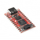
Pro Micro RP2040 Hookup Guide
 bboyho
 Introduction
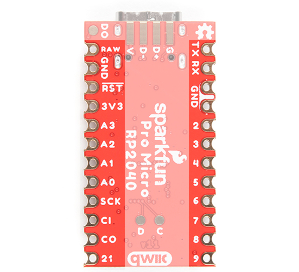
The Pro Micro RP2040 is a low-cost, high-performance board with flexible digital interfaces featuring the Raspberry Pi Foundation's RP2040 microcontroller. The board uses well known Pro Micro footprint with castellated mounting holes.

Required Materials
To follow along with this tutorial, you will need the following materials. You may not need everything though depending on what you have. Add it to your cart, read through the guide, and adjust the cart as necessary.

Tools
You will need a soldering iron, solder, and general soldering accessories for a secure connection when using the plated through hole pads.


Prototyping Accessories
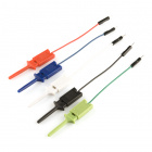
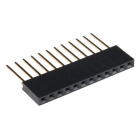
Depending on your setup, you may want to use IC hooks for a temporary connection. However, you will want to solder header pins to connect devices to the plated through holes for a secure connection.


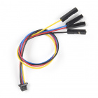
For those that want to take advantage of the Qwiic enabled devices, you'll want to grab a Qwiic cable.

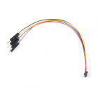
Qwiic Cable - Breadboard Jumper (4-pin)
PRT-14425
Qwiic Cable - 100mm
PRT-14427
Qwiic Cable - 500mm
PRT-14429Suggested Reading
If you aren't familiar with the Qwiic system, we recommend reading here for an overview if you decide to take advantage of the Qwiic connector.
| Qwiic Connect System |
We would also recommend taking a look at the following tutorials if you aren't familiar with them.
How to Solder: Through-Hole Soldering
Serial Communication
Serial Peripheral Interface (SPI)
Pulse Width Modulation
Logic Levels
I2C
Analog vs. Digital
Hardware Overview
Old School to New School
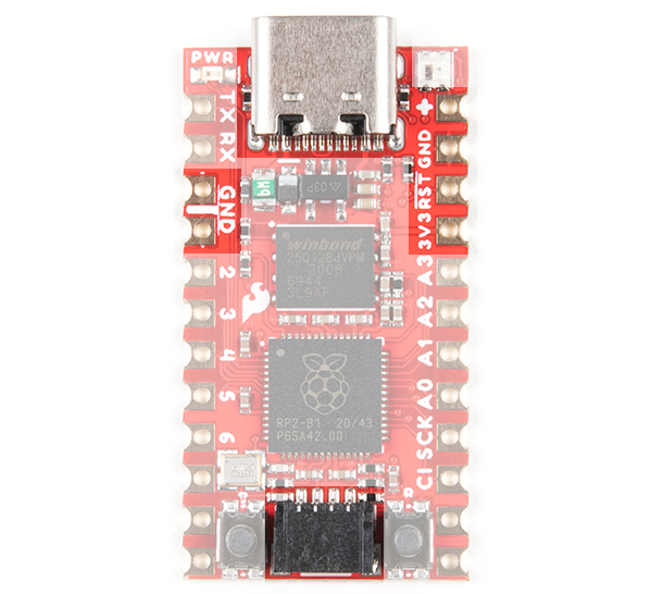
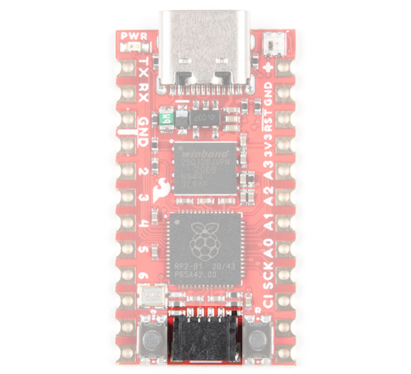
The Pro Micro RP2040 design uses the original Pro Micro and Qwiic Pro Micro USB C's footprint.
 |
 |
| Older Pro Micro with ATmega32U4 |
Newer Qwiic Pro Micro USB C with RP2040 |
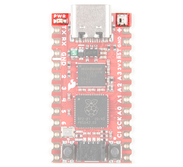
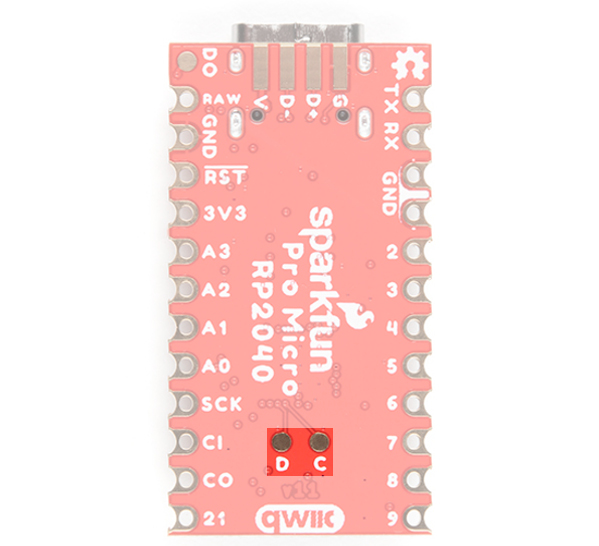
The Pinout
All of the Pro Micro RP2040's GPIO and power pins are broken out to two, parallel headers. Some pins are for power input or output, other pins are dedicated GPIO pins. Further, the GPIO pins can have special function depending on how they are multiplexed Here's a map of which pin is where and what special hardware functions it may have.
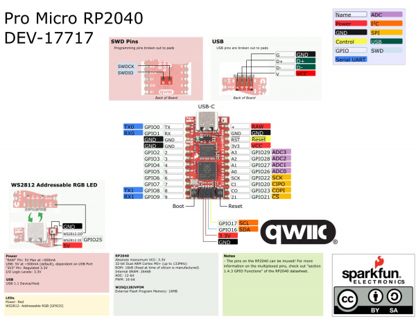
Power
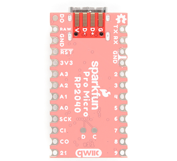
There are a variety of power and power-related nets broken out to connectors and through hole pads. Each pad has a castellated edge. The back of the board also has the USB pins broken out for power
 |
 |
These nets consist of the following:
- V is the voltage provided from the USB connector.
- + is the raw, unregulated voltage input for the Pro Micro RP2040. If the board is powered via USB (i.e. V), the voltage at this pin will be about 4.8V (USB's 5V minus a Schottky diode drop). On the other hand, if the board is powered externally, through this pin, the applied voltage can be up to 5.3V.
- 3.3V is the voltage supplied to the on-board RP2040. We suggest using regulated 3.3V when connecting to this pin. If the board is powered through the raw "+" pin, this pin can be used as an output to supply 3.3V other devices.
- RST can be used to restart the Pro Micro RP2040. There is a built-in reset button to reset the board. However, the pin is broken out if you need to access this pin externally. This pin is pulled high by a 10kΩ resistor on the board, and is active-low, so it must be connected to ground to initiate a reset. The Qwiic Pro Micro will remain "off" until the reset line is pulled back to high.
- GND, of course, is the common, ground voltage (0V reference) for the system.
USB Pins
On the back of the board you can access the USB data pins and power for either USB 1.1 Host or Device.
GPIO Pins
The Pro Micro RP2040 breaks out the GPIO pins to plated through holes pads on the edge of the board. Each pad is castellated as well.
 |
 |
| Top of Board with Edge PTH Pads |
Bottom of Board with Edge PTH Pads |
The Pro Micro's GPIO pins — 20 in all — (if you include the two pins on the Qwiic connector as well) are multi-talented. Every pin can be used as a digital input or output, for blinking LEDs or reading button presses. These pins are referenced via an integer value between 0 and 29.
Four pins feature analog to digital converters (ADCs) and can be used as analog inputs. These are useful for reading potentiometers or other analog devices.
All pins can be set with the pulse width modulation (PWM) functionality, which allows for a form of analog output. The RP2040 can only provide a total of up to 16 controllable PWM outputs.
There are hardware UART (serial), I2C, and SPI pins available as well. These can be used to interface with digital devices like serial LCDs, XBees, IMUs, and other serial sensors.
The RP2040 has 26 external interrupts, which allow you to instantly trigger a function when a pin goes either high, low, or changes state.
Qwiic Connector
The board includes a Qwiic connector to easily connect Qwiic enabled I2C devices to the board. SCL is connected to GPIO17 while SDA is connected to GPIO16
Qwiic Cable - Breadboard Jumper (4-pin)
PRT-14425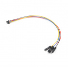
Qwiic Cable - Female Jumper (4-pin)
CAB-14988On-Board LEDs
There are two LEDs on the Pro Micro RP2040. The red LED indicates whether power is present. The other is the addressable WS2812 RGB LED. The addressable LED is connected to GPIO25. You'll to define functions or use the WS2812 library to control that LED.
There is a pad on the back of the board that is connected to the WS2812's DO pin. If you decide to daisy chain more LEDs, you'll want to solder to this pad.
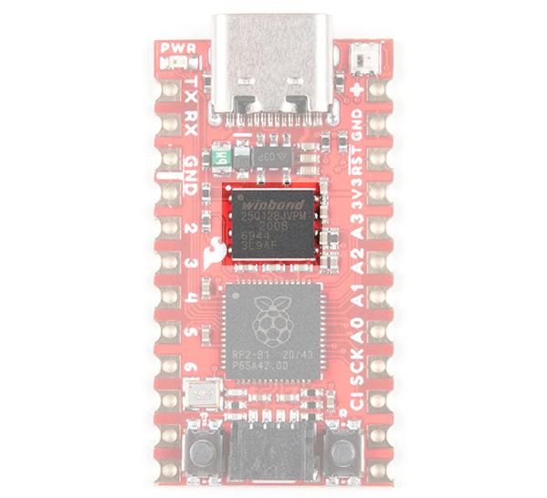
External Flash Memory
The Pro Micro RP2040 includes a W25Q128JVPIM, which adds 128Mb (16MB) of flash memory externally.
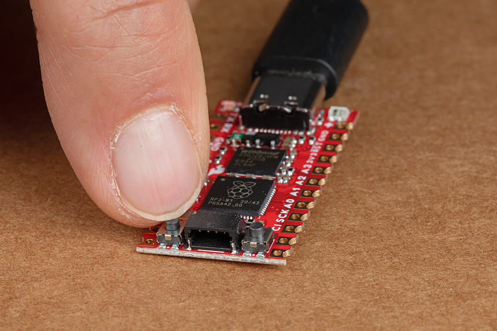
Boot Button
The boot button is connected to the external flash memory. Pressing this button forces USB boot mode so that the board shows up as a USB mass storage device.
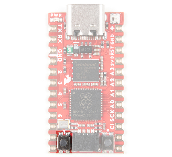
Reset Button
As explained earlier, there is a reset button to reset the RP2040. This adds the option of forcing the RP2040 into bootloader mode without needing to unplug/replug the board back into your USB port. To keep the board size at a minimum, the buttons are not labeled. To distinguish between the two buttons, just remember that the reset button is on the same side of the board as the reset pin.
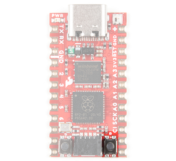
SWD Pins
For advanced users, there are two pins (i.e. D for data/SWDIO and C for clock/SWCLK) on the back broken out for SWD programming on the back of the board. You'll need to solder wire to connect to these pins.
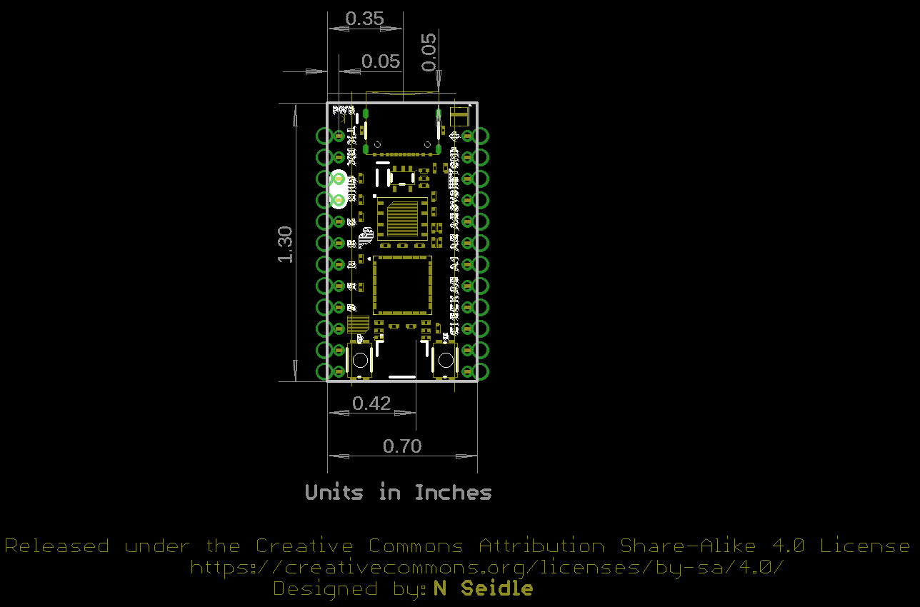
Board Dimensions
The board measures 1.3" x 0.7". Keep in mind that the USB-C connector is not flush with the board and will protude about 0.05" from the edge of the board. Not included in the image below is the PCB thickness, which is 0.8mm. This is thinner than a majority of PCBs used for SparkFun original designs.
Hardware Hookup
Header pins were left off the Pro Micro RP2040 to allow users the flexibility of connecting any type of 0.1" header to the board. For temporary connections to the I/O pins, you could use IC hooks to test out the pins. However, you'll need to solder headers or wires of your choice to the board for a secure connection. For advanced users, you could also design a PCB to take advantage of the castellated edges for a lower profile. Here are a few tutorials to connect to the pads depending on your personal preference.
How to Solder: Through-Hole Soldering
Working with Wire
How to Solder: Castellated Mounting Holes
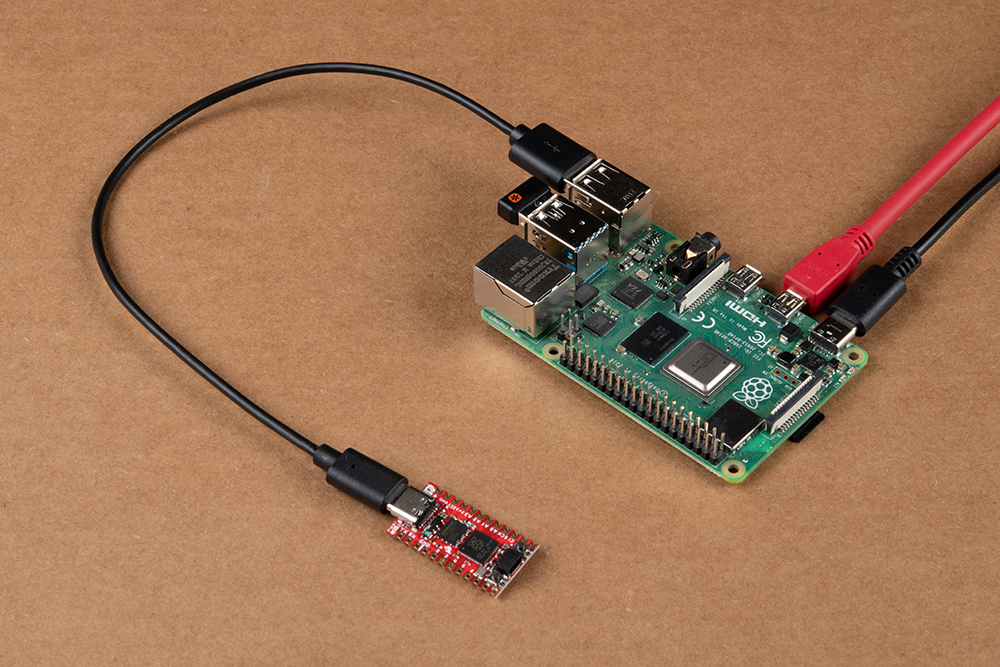
In order to power and upload to the board, you will simply need a USB C cable connected to your computer.
Connecting to GPIO
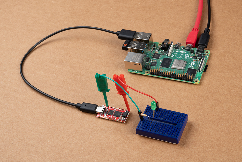
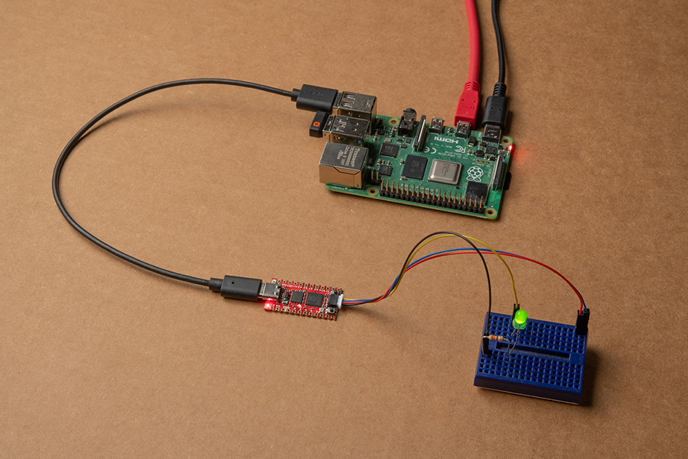
There a few methods of connecting to the GPIO. For a temporary connection when prototyping, you can use IC hooks to connect your circuit to a breadboard. Below is an example of a basic 5mm LED connected to a 330Ω current limiting resistor on a breadboard.
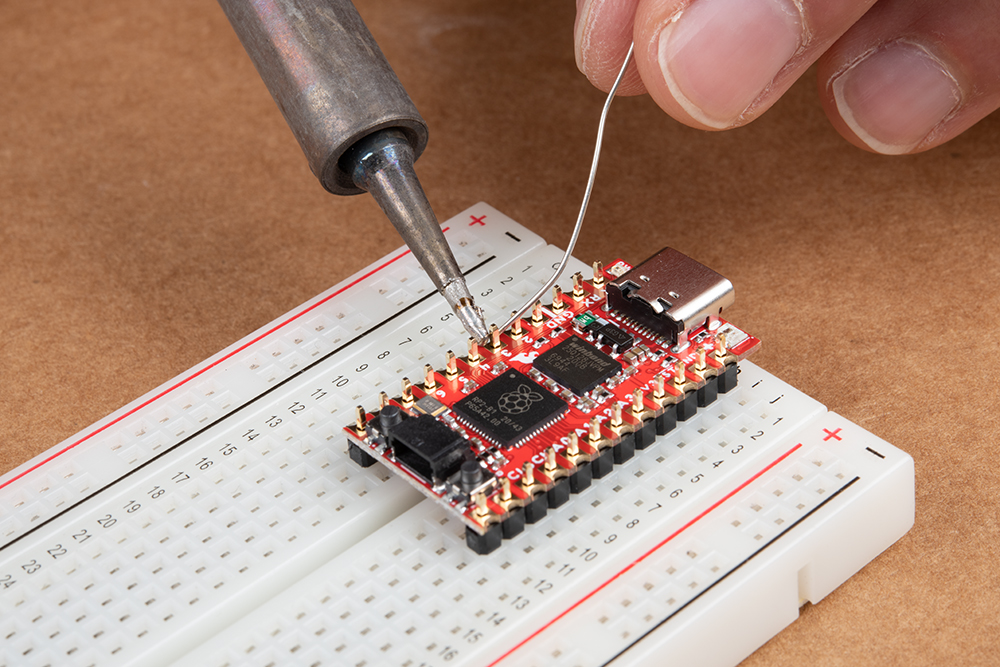
For a secure connection to the Pro Micro RP2040's GPIO, it is recommended to solder header pins. If you designed the board using the footprint, you can also solder the board using the castellated headers. In this case, two 1x12 male header pins are being soldered to the board with the help of a breadboard.
While originally intended to connect Qwiic-enabled devices, you can also use the SDA and SCL pins as a quick, visible test to see if the board is working. In this case, the SCL pin was used as a GPIO pin. Similar to the circuit with the IC hooks, the pin was connected to a basic 5mm LED and a 330Ω current limiting resistor on a breadboard.

Qwiic Enabled Device
You can also easily connect a Qwiic enabled device to the Qwiic connector. Below is an example of the Qwiic VL53L1X distance sensor and Qwiic Micro OLED connected to the Qwiic Pro Micro.

UF2 Bootloader
The Pro Micro 2040 is easy to program, thanks the UF2 bootloader. With this bootloader, the board shows up on your computer as a USB storage device without having to install drivers for Windows 10, Mac, and Linux!
What is UF2?
UF2 stands for USB Flashing Format, which was developed by Microsoft for PXT (now known as MakeCode) for flashing microcontrollers over the Mass Storage Class (MSC), just like a removable flash drive. The file format is unique, so unfortunately, you cannot simply drag and drop a compiled binary or hex file onto the board. Instead, the format of the file has extra information to tell the processor where the data goes, in addition to the data itself. For more information about UF2, you can read more from the MakeCode blog, as well as the UF2 file format specification.
Software Overview
There are two methods of programming the RP2040. You can use MicroPython or C/C++ depending your personal preference. The documentation is written for the Raspberry Pi's Pico development board but will apply for any board with the RP2040. Just make sure to adjust the pin definition depending on what GPIO is broken out.
Examples (MicroPython)
The Raspberry Pi foundation has provided the necessary tools, documentation, and examples to get started with the RP2040. If you haven't already, check out the documentation on the Pico. We'll use this as a reference when using the chip on other development boards to fit your needs in this tutorial.
We'll be using the MicroPython examples from this repo using Thonny IDE.
Installing MicroPython on the RP2040
To install MicroPython on the RP2040, users can download the firmware for Raspberry Pi Pico. Head over to the Raspberry Pi Foundation's RP2040 documentation. Click on the tab for the "MicroPython", scroll down to the Drag-and-Drop MicroPython section, and click the download link for the Raspberry Pi Pico.
Note: Since this tutorial was written, MicroPython has built and released new firmware specifically for the RP2040 Pro Micro. The *.uf2 firmware file can be download from the MicroPython website, by clicking the button below:
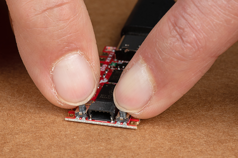
Press and hold the boot button down with one hand.
Press the reset button momentarily.
 |
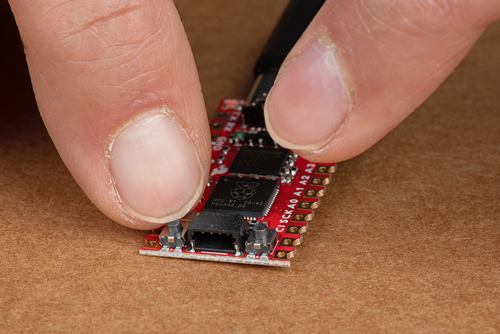 |
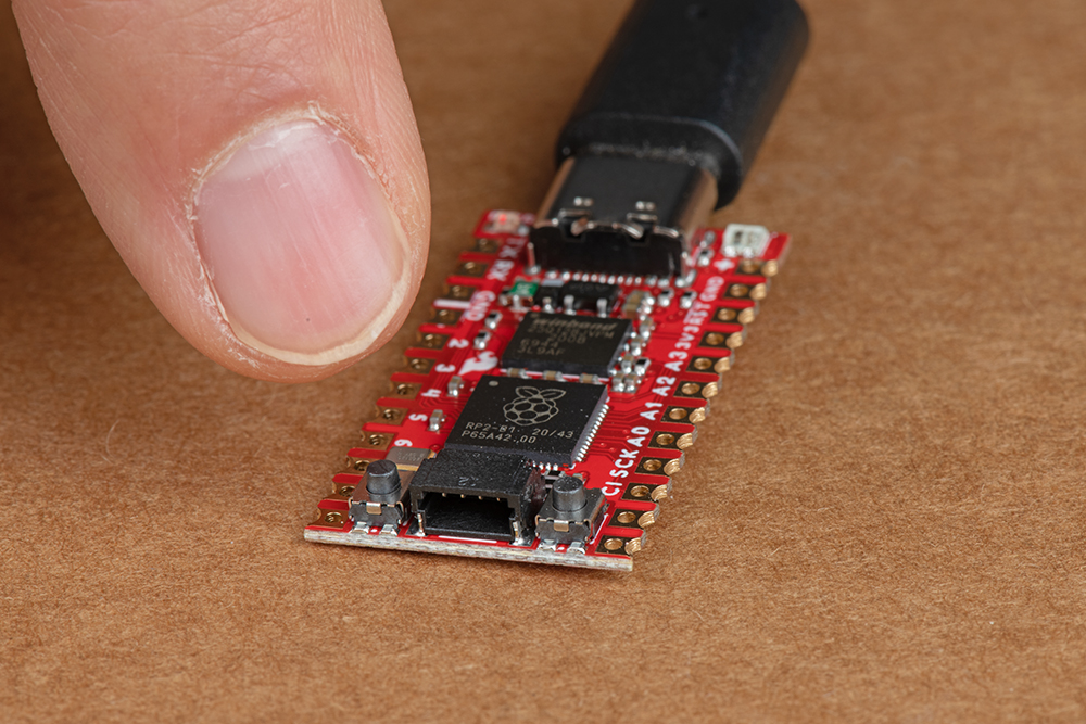
Release the boot button. The board should appear as a removable drive called RPI-RP2.
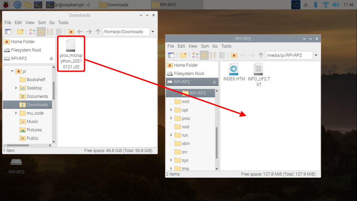
Draw and drop the UF2 file into the "removable drive". The board will automatically reboot. Below is an image highlighting the UF2 file being moved to a the removeable drive on a Raspberry Pi.
Configuring Thonny IDE
&& combines the two commands into a single line and the -y answers "yes" to any prompts. sudo apt update && sudo apt full-upgrade -y
thonny -v
INFO thonny:Thonny version: 3.3.3
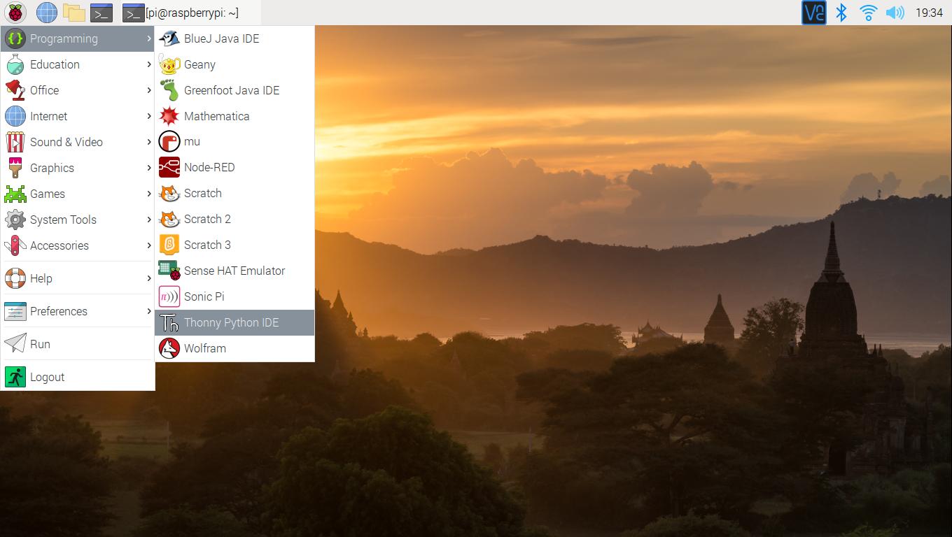
Open Thonny up from the start menu: Raspberry Pi Start Menu > Programming > Thonny Python IDE
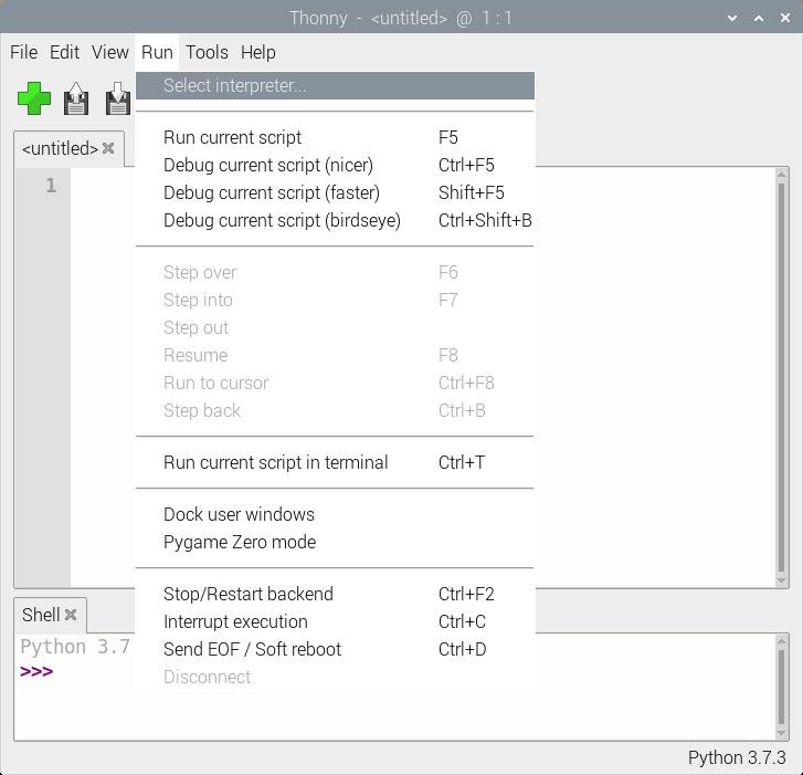
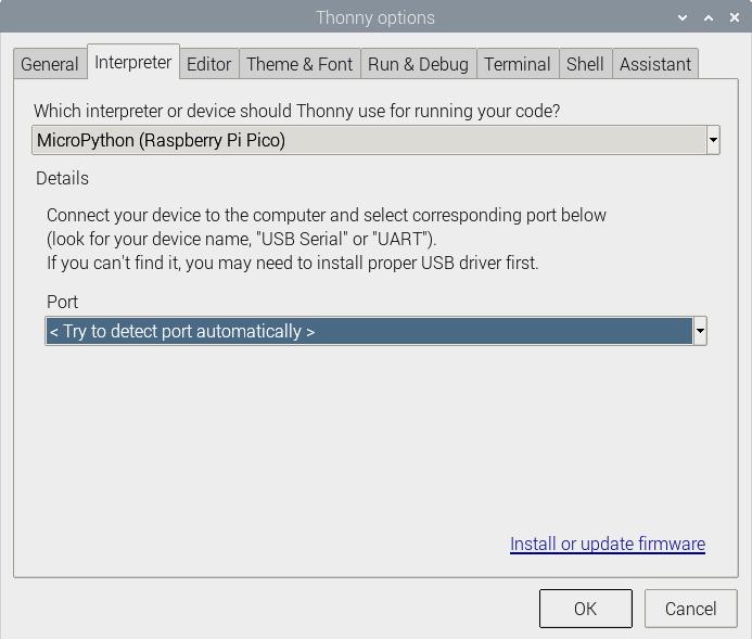
Set Thonny's interpreter for the RP2040. The "Raspberry Pi Pico" will work for the RP2040. Head to the menu and select: Run > Select Interpreter....
This will open a new window for the Thonny options. In the Interpreter tab, select MicroPython (Raspberry Pi Pico) as the interpreter.
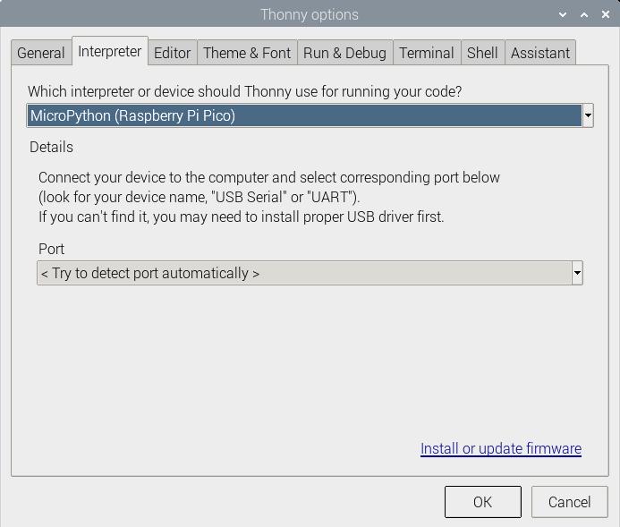
In the same window, make sure to select the option to have Thonny automatically detect the COM port for the board: Port > < Try to detect port automatically >
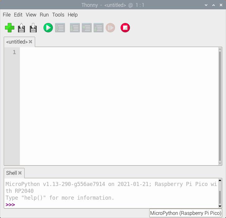
tty(AMA0 (/dev/ttyAMA0).
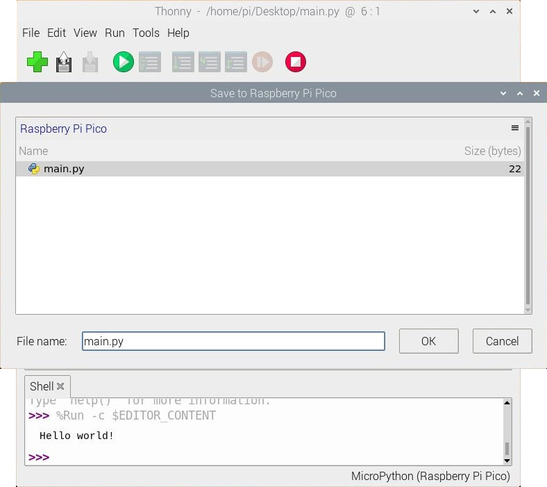
Hello World!
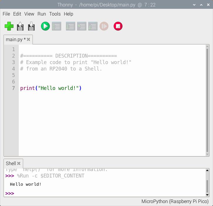
To check if this is working open the Thonny IDE, type the following into the editor. Feel free to adjust the message to whatever you prefer.
language:python
print("Hello world!")
Hit the "Run current script" button. In the Shell, you will see the following output. Sweet!
language:bash
>>> %Run -c %EDITOR_CONTENT
Hello world!
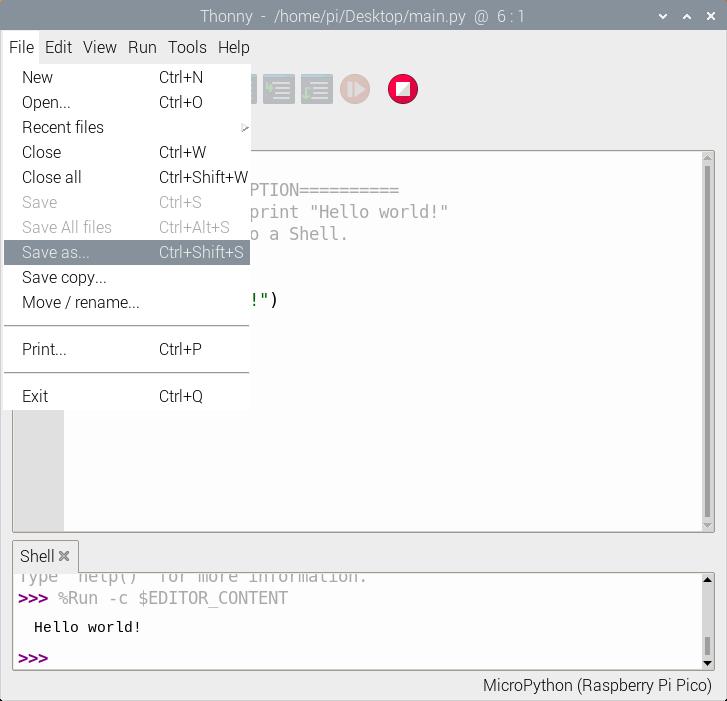
When a window pops up, select Raspberry Pi Pico.
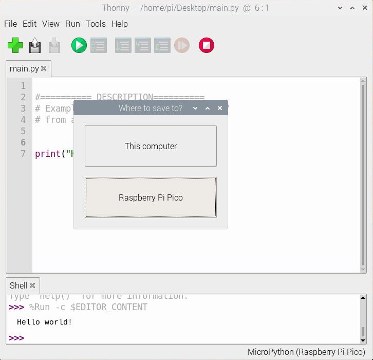
Then save the file as main.py
Just make sure to save any code that was edited on your computer (e.g. Save as... > This computer) before closing Thonny.

Blink
If you have the MicroPython examples saved, head to the following folder in your downloads .../pico-micropython-examples/blink/blink.py . Your code should look like the following. Of course, you can also copy and paste the code provided after the next paragraph as well.
Once you open it in Thonny, adjust the pin number to the GPIO that the LED is connected to. Since we are using the example that was written specifically for the Pico as opposed to the Pro Micro RP2040, we'll need to adjust the pin. In this case, we'll use the RP2040's GPIO17 that is connected to the Qwiic connector so that we do not have to solder pins to the board. This is assuming that we are connecting a current limiting resistor and an LED between the GPIO17 and GND.
language:python
# ========== DESCRIPTION==========
# The following code was originally written by
# the Raspberry Pi Foundation. You can find this
# example on GitHub.
#
#     https://github.com/raspberrypi/pico-micropython-examples/blob/master/blink/blink.py
#
# Note that the GPIO for the LED was adjusted
# for the Pro Micro RP2040. Make sure to use
# a current limiting resistor with the LED.

from machine import Pin, Timer

led = Pin(17, Pin.OUT)
tim = Timer()
def tick(timer):
    global led
    led.toggle()

tim.init(freq=2.5, mode=Timer.PERIODIC, callback=tick)
Hit the "Run current script" button. Once the code runs, you will see the LED blink. If you want the board to run blink every time the board is powered up, just follow the note provided at the end the previous example.
WS2812
If you have the MicroPython examples saved, head to the following folder in your downloads .../pico-micropython-examples/pio/neopixel_ring/neopixel_ring.py . Your code should look like the following. Of course, you can also copy and paste the code provided after the next paragraph as well.
Once you open it in Thonny, adjust the pin number to the GPIO that the LED is connected to for PIN_NUM. Since we are using the example that was written specifically for the Pico as opposed to the Pro Micro 2040, we'll need to adjust the pin. In this case, we'll use the RP2040's GPIO25 that is connected to the WS2812. We will also adjust the NUM_LEDs to 1.
language:python
# ========== DESCRIPTION==========
# Example using PIO to drive a set of WS2812 LEDs.
#
# The following code was originally written by
# the Raspberry Pi Foundation. You can find this
# example on GitHub.
#
#    https://github.com/raspberrypi/pico-micropython-examples/blob/master/pio/neopixel_ring/neopixel_ring.py
#
# Note that the 'NUM_LEDs' was adjusted to 1. Also
# the GPIO for the addressable WS2812 RGB LED called
# `PIN_NUM` was adjusted for the Pro Micro RP2040.

import array, time
from machine import Pin
import rp2

# Configure the number of WS2812 LEDs.
NUM_LEDS = 1
PIN_NUM = 25
brightness = 0.2

@rp2.asm_pio(sideset_init=rp2.PIO.OUT_LOW, out_shiftdir=rp2.PIO.SHIFT_LEFT, autopull=True, pull_thresh=24)
def ws2812():
    T1 = 2
    T2 = 5
    T3 = 3
    wrap_target()
    label("bitloop")
    out(x, 1)               .side(0)    [T3 - 1]
    jmp(not_x, "do_zero")   .side(1)    [T1 - 1]
    jmp("bitloop")          .side(1)    [T2 - 1]
    label("do_zero")
    nop()                   .side(0)    [T2 - 1]
    wrap()


# Create the StateMachine with the ws2812 program, outputting on pin
sm = rp2.StateMachine(0, ws2812, freq=8_000_000, sideset_base=Pin(PIN_NUM))

# Start the StateMachine, it will wait for data on its FIFO.
sm.active(1)

# Display a pattern on the LEDs via an array of LED RGB values.
ar = array.array("I", [0 for _ in range(NUM_LEDS)])

##########################################################################
def pixels_show():
    dimmer_ar = array.array("I", [0 for _ in range(NUM_LEDS)])
    for i,c in enumerate(ar):
        r = int(((c >> 8) & 0xFF) * brightness)
        g = int(((c >> 16) & 0xFF) * brightness)
        b = int((c & 0xFF) * brightness)
        dimmer_ar[i] = (g<<16) + (r<<8) + b
    sm.put(dimmer_ar, 8)
    time.sleep_ms(10)

def pixels_set(i, color):
    ar[i] = (color[1]<<16) + (color[0]<<8) + color[2]

def pixels_fill(color):
    for i in range(len(ar)):
        pixels_set(i, color)

def color_chase(color, wait):
    for i in range(NUM_LEDS):
        pixels_set(i, color)
        time.sleep(wait)
        pixels_show()
    time.sleep(0.2)

def wheel(pos):
    # Input a value 0 to 255 to get a color value.
    # The colours are a transition r - g - b - back to r.
    if pos < 0 or pos > 255:
        return (0, 0, 0)
    if pos < 85:
        return (255 - pos * 3, pos * 3, 0)
    if pos < 170:
        pos -= 85
        return (0, 255 - pos * 3, pos * 3)
    pos -= 170
    return (pos * 3, 0, 255 - pos * 3)


def rainbow_cycle(wait):
    for j in range(255):
        for i in range(NUM_LEDS):
            rc_index = (i * 256 // NUM_LEDS) + j
            pixels_set(i, wheel(rc_index & 255))
        pixels_show()
        time.sleep(wait)

BLACK = (0, 0, 0)
RED = (255, 0, 0)
YELLOW = (255, 150, 0)
GREEN = (0, 255, 0)
CYAN = (0, 255, 255)
BLUE = (0, 0, 255)
PURPLE = (180, 0, 255)
WHITE = (255, 255, 255)
COLORS = (BLACK, RED, YELLOW, GREEN, CYAN, BLUE, PURPLE, WHITE)

print("fills")
for color in COLORS:
    pixels_fill(color)
    pixels_show()
    time.sleep(0.2)

print("chases")
for color in COLORS:
    color_chase(color, 0.01)

while True:
    print("rainbow")
    rainbow_cycle(0)
Hit the "Run current script" button. Once the code runs, it will display each color at "0.2" brightness. The LED will then animate. Since there is only one LED attached, it will look like it will be blinking through the colors. Once the board jumps into the while loop, the LED will begin cycling between colors smoothly. Remember, you can have the board run the example every time the board is powered up by following the note provided in an earlier example.
If you are looking to simplify the code, you can also use the library written for the WS2812. This saves some of the functions in a separate file. Just make sure to adjust the GPIO to connect to the WS2812(s) and the number of LEDs.
Resources and Going Further
For more information, check out the resources below:
- Schematic (PDF)
- Eagle Files (ZIP)
- Board Dimensions (PNG)
- Graphical Datasheet (PDF)
- RP2040 Datasheet (PDF) (31.2 MB)
- Raspberry Pi Pico Datasheet (PDF) (16.5MB) - An RP2040-based microcontroller board
- Getting Started with Raspberry Pi Pico (PDF) (32.9MB) - C/C++ development with Raspberry Pi Pico and other RP2040-based microcontroller boards
- Raspberry Pi Pico C/C++ SDK (PDF) (2.14MB) - Libraries and tools for C/C++ development on RP2040 microcontrollers
- Raspberry Pi Pico Python SDK (PDF) (2.66MB) - A MicroPython environment for RP2040 microcontrollers
- RP2040 Informational Page
- GitHub Repo