PIR Motion Sensor Hookup Guide
 jimblom
 PIR Motion Sensor Overview
At their most fundamental level, PIR sensor's are infrared-sensitive light detectors. By monitoring light in the infrared spectrum, PIR sensors can sense subtle changes in temperature across the area they're viewing. When a human or some other object comes into the PIR's field-of-view, the radiation pattern changes, and the PIR interprets that change as movement.
That white cap dominating most of the top side of the PIR assembly is a lens, which helps focus the PIR sensor's field-of-view. The actual PIR sensor is hiding under that lens:
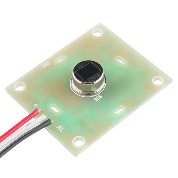
The back side of the assembly sports amplifiers, voltage regulators and other supporting circuitry to help drive the PIR. All that's left for us to connect is three pins: power, ground, and the output signal.
Power and Signal Pins
The top side of the PIR assembly includes two labels: "+" and "AL". The "AL" pin is the alarm pin -- don't let the black wire fool you, this isn't ground! "+" is the PIR sensor's power supply input, leaving the unlabeled middle pin, with the white wire, as ground.
| Wire Color | Pin | Notes |
|---|---|---|
| Red | Power | 5V[1] to 12V |
| White | Ground | |
| Black | Alarm | Open-collector output – active low |
The PIR sensor should be powered with at least 5V, but it can work with voltages as high as 12V. Fortunately, even if a PIR is powered higher than 5V, the alarm pin can still connect directly to an input pin because it is designed as an open-collector.
When the PIR senses activity in it's viewing area, it pulls the alarm pin low. But when the sensor is inactive, the pin is basically floating. To avoid any false-positives, the alarm output should be pulled high to 5V. Most microcontroller's have internal pull-up resistors on their I/O pins, which can easily accomplish that task. You can also pull it high to 3.3V if you are using it with a 3.3V system (e.g. 3.3V Arduino or Raspberry Pi).
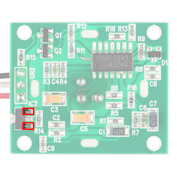
Bypass Jumper - If you only have 5V available (e.g. you are pulling 5V from the Arduino's USB, Particle Photon's USB, or Raspberry Pi), you could bypass the voltage regulator by adding a jumper between the L78L05's VIN and VOUT pins. Just make sure that the voltage is regulated and clean. The images below highlightt the pins to bypass the voltage regulator. The pins of the SMD voltage regulator are small so you could also solder wire directly to the "+" pin as well.
 |
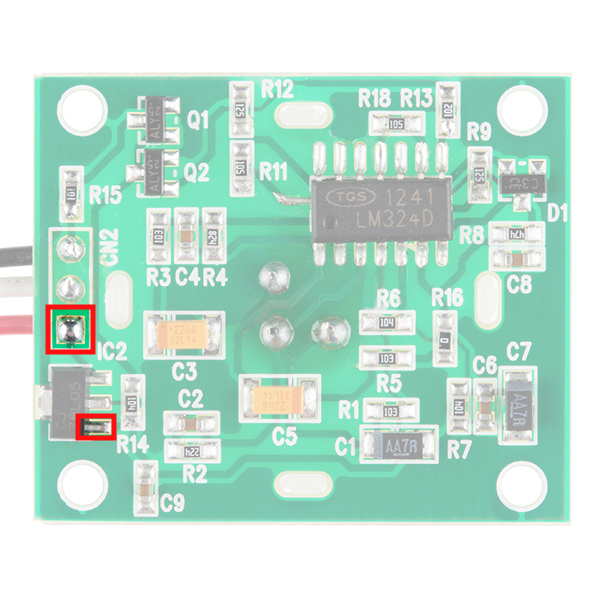 |
| VIN and VOUT Pins Highlighted | "+" and VOUT Pins Highlighted |