PicoBuck Hookup Guide
This Tutorial is Retired!
This tutorial covers concepts or technologies that are no longer current. It's still here for you to read and enjoy, but may not be as useful as our newest tutorials.
View the updated tutorial: PicoBuck Hookup Guide v12
 SFUptownMaker
Introduction
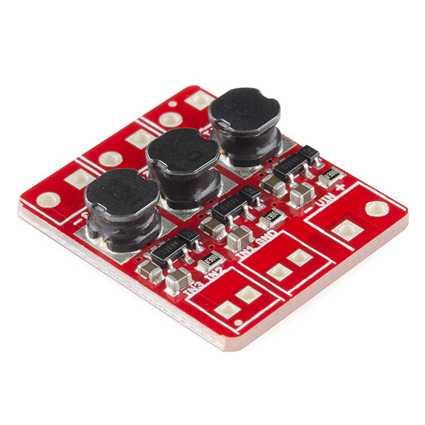
Developed in collaboration with Ethan Zonca of protofusion, the PicoBuck is a small-size triple-output constant current LED driver. By default, each channel is driven at 350mA; that current can be reduced by either presenting an analog voltage or a PWM signal to the board.
Suggested Reading
Here are some topics you should know before using the PicoBuck. Have a look if you need more information.
PicoBuck Overview
Connecting the PicoBuck
While the AL8805 chip can be driven at voltages of up to 36V, to keep the size of the board small we used lower voltage capacitors, so keep the system supply voltage lower than 18V for a fair safety margin.
Since the PicoBuck is a constant current driver, the current drawn from the supply will drop as supply voltage rises. At 12V, the PicoBuck drives the three LEDs on our Rebel Triple Play board at 350mA per LED while drawing less than 350mA from the power supply.
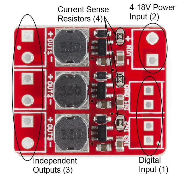
Three signal inputs (1) are provided for dimming control. A separate ground pin is provided to reference against the controlling module for accuracy. The pin spacing for the three two pairs of pins is .1", but the two pairs are slightly more than .1" apart, to allow for a 2.54mm pitch screw terminal pair to be used. Dimming can be done by an analog voltage (20%-100% of max current by varying voltage from .5V-2.5V) or by PWM (so long as PWM minimum voltage is less than .4V and maximum voltage is more than 2.4V) for a full 0-100% range.
The power supply pads (2) are sized for 3.5mm screw terminals, as are the output pads (3). Each output is independent from the other two; the PicoBuck cannot be used to drive a common anode or common cathode LED or LED string.
It is possible to increase the maximum current of the PicoBuck board up to 1A per channel; to do so, replace the three current sense resistors (4) with smaller values. To calculate the new value for the resistor, use this formula: ILED = 0.1 / Rset. Thus, for a 1A current, you'd want a .1Ω resistor. Don't forget to be wary of current ratings; at 1A, the sense resistor will be dissipating 1/10W, so you probably want a resistor of at least 1/8W rating. The package is a standard 0805.
Additional Resources
Consider checking out these other tutorials for more information about concepts in this guide: