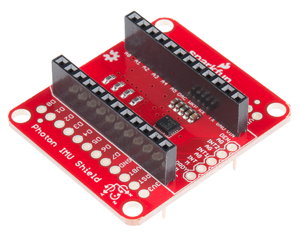
Does your Photon project need an accelerometer? What about a gyroscope or a magnetometer? With the SparkFun Photon IMU Shield, you can get all three, thanks to the LSM9DS1 IC module.
The SparkFun Photon IMU (Inertial Measurement Unit) Shield is a versatile motion-sensing add-on board for your Photon device that houses a 3-axis accelerometer, 3-axis gyroscope, and 3-axis magnetometer. That’s right, 9 degrees of freedom (9DOF) from a single IC!
Each sensor in the LSM9DS1 supports a large variety of ranges: the accelerometer’s scale can be set to ± 2, 4, 6, 8, or 16 g, the gyroscope supports ± 245, 500, and 2000 °/s, and the magnetometer has full-scale ranges of ± 2, 4, 8, or 12 gauss. As a bonus, the SparkFun Photon IMU Shield comes with the headers already soldered on, so you can plug your Photon (or Core) in and get started!
This tutorial will cover the functionality of the IMU shield, how to hook it up in your project, and how to program with it using the SparkFun LSM9DS1 Library from the online Particle build environment.
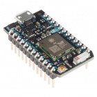
To get started with the Photon IMU Shield you'll want a Photon, a micro-USB cable, and of course the shield itself. You'll also want to sign up for an account on particle.io and register your Photon. Instructions on how to do this can be found at docs.particle.io.
Here's a few things you may want to brush up on or dive into if you plan on making the most of your IMU Shield.
Since the shield does all of the work for you, there's no need to actually wire these connections - but in case you're looking at datasheets, or code examples, this table will give you a clue as to what the shield is doing. As always, you can check the schematic for more info.
| IMU Shield Pin | Photon Pin | Function |
|---|---|---|
| GND | GND | Ground |
| VDD | 3.3V | Regulated 3.3V in |
| SCL | D1 | SCL Serial clock |
| SDA | D0 | Serial Data in |
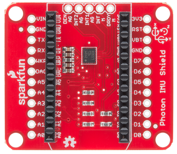
We also broke out a few pins at the top of the board that some of you may wish to make use of. From left to right in the picture above, they are:
| IMU Shield Pin | Function |
|---|---|
| DEN AG | Data Enable Accel/Gyro |
| INT2 AG | Programmable Interrupt Accel/Gyro |
| INT1 AG | Programmable Interrupt Accel/Gyro |
| INT M | Programmable Interrupt Magnetometer |
| DRDY M | Magnetic sensor data ready |
With the board flipped over, you'll notice there are six jumpers. The majority of these jumpers are used to switch between SPI and I2C mode. As the board ships, these jumpers are set to configure the IMU in I2C mode.
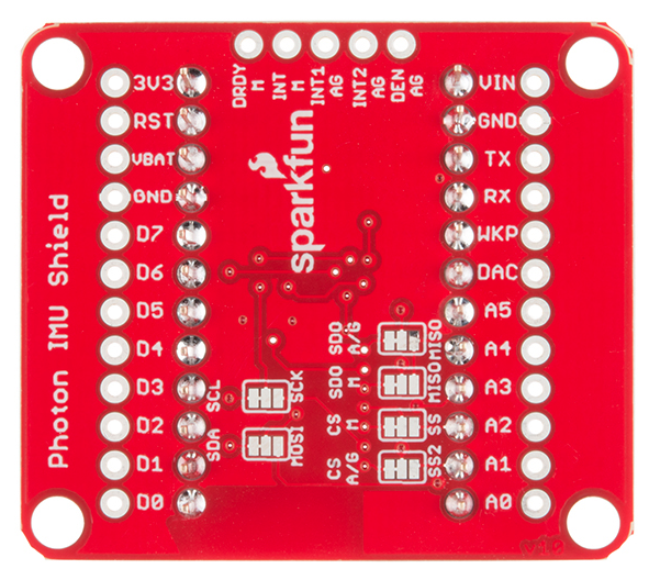
The SDO M-MISO and SDO A/G-MISO jumpers can be used to set the I2C addresses (In I2C mode) or, if open, can be used either to set I2C address or for SPI control. The default out of the box has both jumpers pulled high for I2C mode.
| SDOM /AG | AG Addr. | M Addr. |
|---|---|---|
| 0 | 0x6A | 0x1C |
| 1 | 0x6B | 0x1E |
The CS A/G-SS2 and CS M-SS are the chip select jumpers for the accelerometer/gyro and the magnetometer, respectively. The board ships with them both pulled high to enable I2C mode. Close the jumpers and cut the former traces to enable SPI mode.
The same story holds true for the SDA-MOSI and SCL-SCK jumpers. They are pulled high to enable I2C communication. Close the jumpers in the other direction and cut the former traces to enable SPI mode.
Now that we understand the IMU hardware, let's put some code on this thing and see what it can do. Using the Particle library we've written, you'll be able to capture acceleration, angular rotation, and magnetic field strength with ease!
For this page we'll be using the online Particle environment. If you're using the Particle Dev environment instead, you can get the library and code examples from the GitHub repository.
If you haven't created a Particle user account and claimed your board, you'll need to do that now. Starting here is a great idea if you're having trouble.
Once you're logged into build.particle.io and have a device selected (all this is covered at the link above), you'll want to click on the create new app button in the sidebar -- it's big and blue, you can't miss it. Call your app something like 'IMU_test'.
Next -- this is the important part -- we include the LSM9DS1 library. To do this:
It should look something like this:
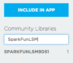
#include "SparkFunLSM9DS1/SparkFunLSM9DS1.h" at the top of your app.Now that we've included the library in our app, let's give it some code - just copy the demo code below and paste it into your app, below the include statements. NOTE: this example uses I2C - check out the "LSM9DS1_BASIC_SPI.CPP" file in the Particle library for and SPI example.
language:cpp
/*****************************************************************
LSM9DS1_Basic_I2C.ino
SFE_LSM9DS1 Library Simple Example Code - I2C Interface
Jim Lindblom @ SparkFun Electronics
Original Creation Date: April 30, 2015
https://github.com/sparkfun/SparkFun_LSM9DS1_Particle_Library

The LSM9DS1 is a versatile 9DOF sensor. It has a built-in
accelerometer, gyroscope, and magnetometer. Very cool! Plus it
functions over either SPI or I2C.

This Photon sketch is a demo of the simple side of the
SFE_LSM9DS1 library. It'll demo the following:
* How to create a LSM9DS1 object, using a constructor (global
  variables section).
* How to use the begin() function of the LSM9DS1 class.
* How to read the gyroscope, accelerometer, and magnetometer
  using the readGryo(), readAccel(), readMag() functions and
  the gx, gy, gz, ax, ay, az, mx, my, and mz variables.
* How to calculate actual acceleration, rotation speed,
  magnetic field strength using the calcAccel(), calcGyro()
  and calcMag() functions.
* How to use the data from the LSM9DS1 to calculate
  orientation and heading.

Hardware setup: This library supports communicating with the
LSM9DS1 over either I2C or SPI. This example demonstrates how
to use I2C.

If you have the Photon IMU shield, no extra wiring is required.
If you're using a breakout, the pin-out is as follows:
    LSM9DS1 --------- Photon
     SCL -------------- D1 (SCL)
     SDA -------------- D0 (SDA)
     VDD ------------- 3.3V
     GND ------------- GND
(CSG, CSXM, SDOG, and SDOXM should all be pulled high.
Jumpers on the breakout board will do this for you.)

Development environment specifics:
    IDE: Particle Build
    Hardware Platform: Particle Photon
                       SparkFun Photon IMU Shield

This code is released under the MIT license.

Distributed as-is; no warranty is given.
*****************************************************************/
#include "SparkFunLSM9DS1/SparkFunLSM9DS1.h"
#include "math.h"

//////////////////////////
// LSM9DS1 Library Init //
//////////////////////////
// Use the LSM9DS1 class to create an object. [imu] can be
// named anything, we'll refer to that throught the sketch.
LSM9DS1 imu;

///////////////////////
// Example I2C Setup //
///////////////////////
// SDO_XM and SDO_G are both pulled high, so our addresses are:
#define LSM9DS1_M   0x1E // Would be 0x1C if SDO_M is LOW
#define LSM9DS1_AG  0x6B // Would be 0x6A if SDO_AG is LOW

////////////////////////////
// Sketch Output Settings //
////////////////////////////
#define PRINT_CALCULATED
//#define PRINT_RAW
#define PRINT_SPEED 250 // 250 ms between prints

// Earth's magnetic field varies by location. Add or subtract
// a declination to get a more accurate heading. Calculate
// your's here:
// http://www.ngdc.noaa.gov/geomag-web/#declination
#define DECLINATION -8.58 // Declination (degrees) in Boulder, CO.

void setup()
{

  Serial.begin(115200);

  // Before initializing the IMU, there are a few settings
  // we may need to adjust. Use the settings struct to set
  // the device's communication mode and addresses:
  imu.settings.device.commInterface = IMU_MODE_I2C;
  imu.settings.device.mAddress = LSM9DS1_M;
  imu.settings.device.agAddress = LSM9DS1_AG;
  // The above lines will only take effect AFTER calling
  // imu.begin(), which verifies communication with the IMU
  // and turns it on.
  if (!imu.begin())
  {
    Serial.println("Failed to communicate with LSM9DS1.");
    Serial.println("Double-check wiring.");
    Serial.println("Default settings in this sketch will " \
                  "work for an out of the box LSM9DS1 " \
                  "Breakout, but may need to be modified " \
                  "if the board jumpers are.");
    while (1)
      ;
  }
}

void loop()
{
  printGyro();  // Print "G: gx, gy, gz"
  printAccel(); // Print "A: ax, ay, az"
  printMag();   // Print "M: mx, my, mz"

  // Print the heading and orientation for fun!
  // Call print attitude. The LSM9DS1's magnetometer x and y
  // axes are opposite to the accelerometer, so my and mx are
  // substituted for each other.
  printAttitude(imu.ax, imu.ay, imu.az, -imu.my, -imu.mx, imu.mz);
  Serial.println();

  delay(PRINT_SPEED);
}

void printGyro()
{
  // To read from the gyroscope, you must first call the
  // readGyro() function. When this exits, it'll update the
  // gx, gy, and gz variables with the most current data.
  imu.readGyro();

  // Now we can use the gx, gy, and gz variables as we please.
  // Either print them as raw ADC values, or calculated in DPS.
  Serial.print("G: ");
#ifdef PRINT_CALCULATED
  // If you want to print calculated values, you can use the
  // calcGyro helper function to convert a raw ADC value to
  // DPS. Give the function the value that you want to convert.
  Serial.print(imu.calcGyro(imu.gx), 2);
  Serial.print(", ");
  Serial.print(imu.calcGyro(imu.gy), 2);
  Serial.print(", ");
  Serial.print(imu.calcGyro(imu.gz), 2);
  Serial.println(" deg/s");
#elif defined PRINT_RAW
  Serial.print(imu.gx);
  Serial.print(", ");
  Serial.print(imu.gy);
  Serial.print(", ");
  Serial.println(imu.gz);
#endif
}

void printAccel()
{
  // To read from the accelerometer, you must first call the
  // readAccel() function. When this exits, it'll update the
  // ax, ay, and az variables with the most current data.
  imu.readAccel();

  // Now we can use the ax, ay, and az variables as we please.
  // Either print them as raw ADC values, or calculated in g's.
  Serial.print("A: ");
#ifdef PRINT_CALCULATED
  // If you want to print calculated values, you can use the
  // calcAccel helper function to convert a raw ADC value to
  // g's. Give the function the value that you want to convert.
  Serial.print(imu.calcAccel(imu.ax), 2);
  Serial.print(", ");
  Serial.print(imu.calcAccel(imu.ay), 2);
  Serial.print(", ");
  Serial.print(imu.calcAccel(imu.az), 2);
  Serial.println(" g");
#elif defined PRINT_RAW
  Serial.print(imu.ax);
  Serial.print(", ");
  Serial.print(imu.ay);
  Serial.print(", ");
  Serial.println(imu.az);
#endif

}

void printMag()
{
  // To read from the magnetometer, you must first call the
  // readMag() function. When this exits, it'll update the
  // mx, my, and mz variables with the most current data.
  imu.readMag();

  // Now we can use the mx, my, and mz variables as we please.
  // Either print them as raw ADC values, or calculated in Gauss.
  Serial.print("M: ");
#ifdef PRINT_CALCULATED
  // If you want to print calculated values, you can use the
  // calcMag helper function to convert a raw ADC value to
  // Gauss. Give the function the value that you want to convert.
  Serial.print(imu.calcMag(imu.mx), 2);
  Serial.print(", ");
  Serial.print(imu.calcMag(imu.my), 2);
  Serial.print(", ");
  Serial.print(imu.calcMag(imu.mz), 2);
  Serial.println(" gauss");
#elif defined PRINT_RAW
  Serial.print(imu.mx);
  Serial.print(", ");
  Serial.print(imu.my);
  Serial.print(", ");
  Serial.println(imu.mz);
#endif
}

// Calculate pitch, roll, and heading.
// Pitch/roll calculations take from this app note:
// http://cache.freescale.com/files/sensors/doc/app_note/AN3461.pdf?fpsp=1
// Heading calculations taken from this app note:
// http://www51.honeywell.com/aero/common/documents/myaerospacecatalog-documents/Defense_Brochures-documents/Magnetic__Literature_Application_notes-documents/AN203_Compass_Heading_Using_Magnetometers.pdf
void printAttitude(
float ax, float ay, float az, float mx, float my, float mz)
{
  float roll = atan2(ay, az);
  float pitch = atan2(-ax, sqrt(ay * ay + az * az));

  float heading;
  if (my == 0)
    heading = (mx < 0) ? 180.0 : 0;
  else
    heading = atan2(mx, my);

  heading -= DECLINATION * M_PI / 180;

  if (heading > M_PI) heading -= (2 * M_PI);
  else if (heading < -M_PI) heading += (2 * M_PI);
  else if (heading < 0) heading += 2 * M_PI;

  // Convert everything from radians to degrees:
  heading *= 180.0 / M_PI;
  pitch *= 180.0 / M_PI;
  roll  *= 180.0 / M_PI;

  Serial.print("Pitch, Roll: ");
  Serial.print(pitch, 2);
  Serial.print(", ");
  Serial.println(roll, 2);
  Serial.print("Heading: "); Serial.println(heading, 2);
}
Now hit the 'flash' button (the one that looks like a lightning bolt) and wait for the magic to begin!
Here are a few links that should help with any further questions you may have about the Photon IMU Shield:
Now that you're comfortable with the Photon IMU Shield and its Particle library, what are you going to make with it? Need some inspiration? Check out these related tutorials:
The IMU Shield pairs very well with any of our other Photon Shields; check out our hookup guides for those shields:
Or check out this blog post for ideas:
learn.sparkfun.com | CC BY-SA 3.0 | SparkFun Electronics | Niwot, Colorado