OpenPIR Hookup Guide
 jimblom,
  SFUptownMaker
Software
The firmware example below uses Arduino to demonstrate how both the digital output and analog output can be used. Here is the example circuit used in the example code:
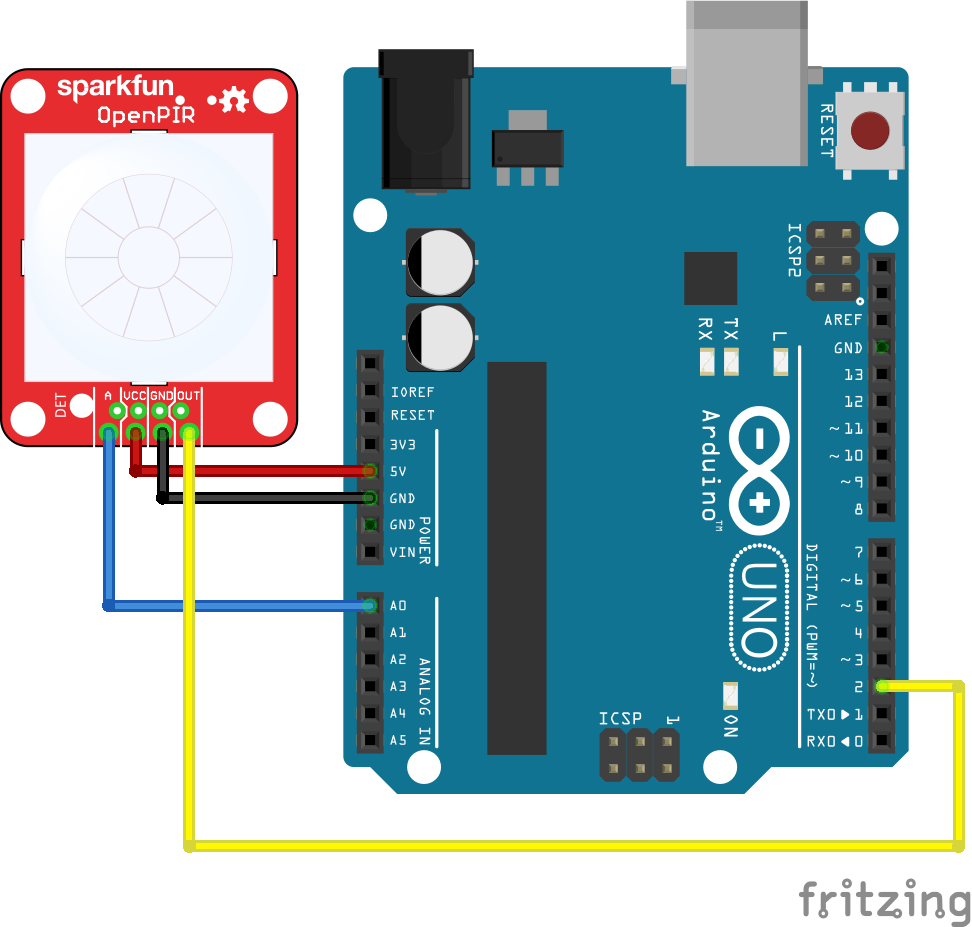
Then upload the example code below so you can begin to get a feel for the OpenPIR's output pins:
language:c
//////////////////////////
// Hardware Definitions //
//////////////////////////
#define PIR_AOUT A0  // PIR analog output on A0
#define PIR_DOUT 2   // PIR digital output on D2
#define LED_PIN  13  // LED to illuminate on motion

#define PRINT_TIME 100 // Rate of serial printouts
unsigned long lastPrint = 0; // Keep track of last serial out

void setup()
{
  Serial.begin(115200);  // Serial is used to view Analog out
  // Analog and digital pins should both be set as inputs:
  pinMode(PIR_AOUT, INPUT);
  pinMode(PIR_DOUT, INPUT);

  // Configure the motion indicator LED pin as an output
  pinMode(LED_PIN, OUTPUT);
  digitalWrite(LED_PIN, LOW); // Turn the LED off
}

void loop()
{
  // Read OUT pin, and set onboard LED to mirror output
  readDigitalValue();

  // Read A pin, print that value to serial port:
  printAnalogValue();
}

void readDigitalValue()
{
  // The OpenPIR's digital output is active high
  int motionStatus = digitalRead(PIR_DOUT);

  // If motion is detected, turn the onboard LED on:
  if (motionStatus == HIGH)
    digitalWrite(LED_PIN, HIGH);
  else // Otherwise turn the LED off:
    digitalWrite(LED_PIN, LOW);
}

void printAnalogValue()
{
  if ( (lastPrint + PRINT_TIME) < millis() )
  {
    lastPrint = millis();
    // Read in analog value:
    unsigned int analogPIR = analogRead(PIR_AOUT);
    // Convert 10-bit analog value to a voltage
    // (Assume high voltage is 5.0V.)
    float voltage = (float) analogPIR / 1024.0 * 5.0;
    // Print the reading from the digital pin.
    // Mutliply by 5 to maintain scale with AOUT.
    Serial.print(5 * digitalRead(PIR_DOUT));
    Serial.print(',');    // Print a comma
    Serial.print(2.5);    // Print the upper limit
    Serial.print(',');    // Print a comma
    Serial.print(1.7);    // Print the lower limit
    Serial.print(',');    // Print a comma
    Serial.print(voltage); // Print voltage
    Serial.println();
  }
}
This code uses the Arduino's onboard LED --- on pin 13 --- to reflect the OpenPIR's digital motion output. When motion is detected, the Arduino's LED should illuminate.
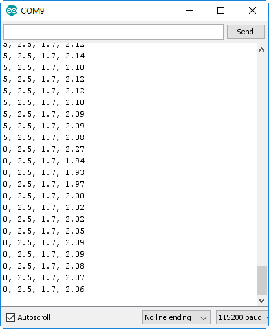
Four values are printed to the serial terminal --- the reading from the digital pin (multiplied by 5...for a reason), the upper and lower comparator voltage thresholds and the reading from the analog pin. Open up your serial monitor --- setting the baud rate to 115200 --- to see them stream by:
Since it may be difficult to visualize the sensor's analog output using the serial terminal, try opening up the serial plotter (found under the "Tools" > "Serial Plotter" menu).
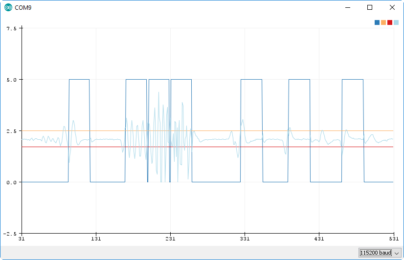
You should see two separate line graphs: the light blue indicating the analog value and the dark blue representing the digital output. The orange and red straight lines represent the upper and lower thresholds, which the analog value must exceed to trigger motion.
Wave at the sensor to get a better feel for the analog output's behavior. And make sure you try both single and dual modes to see how the switch alters the sensor's functionality.