OpenPIR Hookup Guide
Contributors:
 jimblom,
  SFUptownMaker
jimblom, SFUptownMaker 
Hardware Assembly
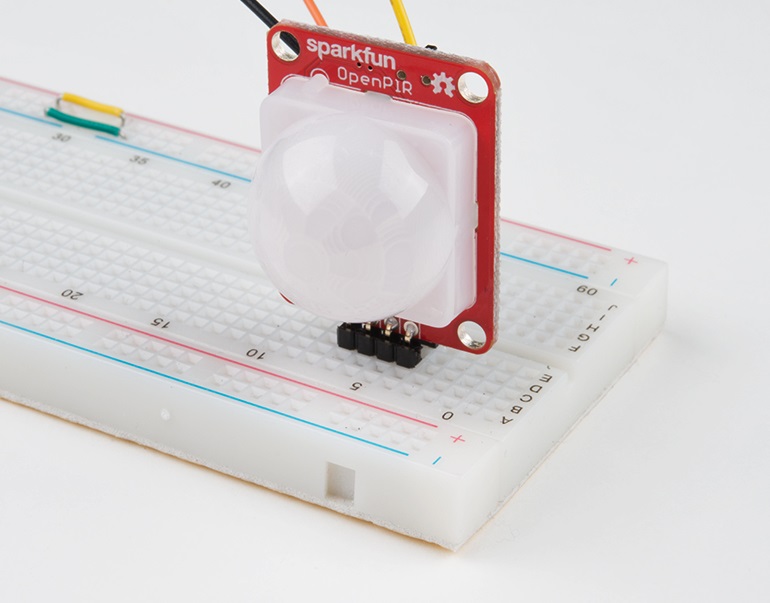
Before you can power the OpenPIR and connect it to a project, you'll need to solder something to the quartet of pins on the bottom of the board.
New to soldering? Check out our Through-Hole Soldering Tutorial for a quick introduction!
The OpenPIR's power and output pins are broken out to both a standard 0.1" header and a 4-pin JST PH connector, leaving you a number of options for what, exactly, you'll solder to the sensor. To the 0.1" header, you can solder male headers (or the right-angle version), female headers or wire.
Or you can solder a 4-Pin JST connector to the smaller-pitch footprint.
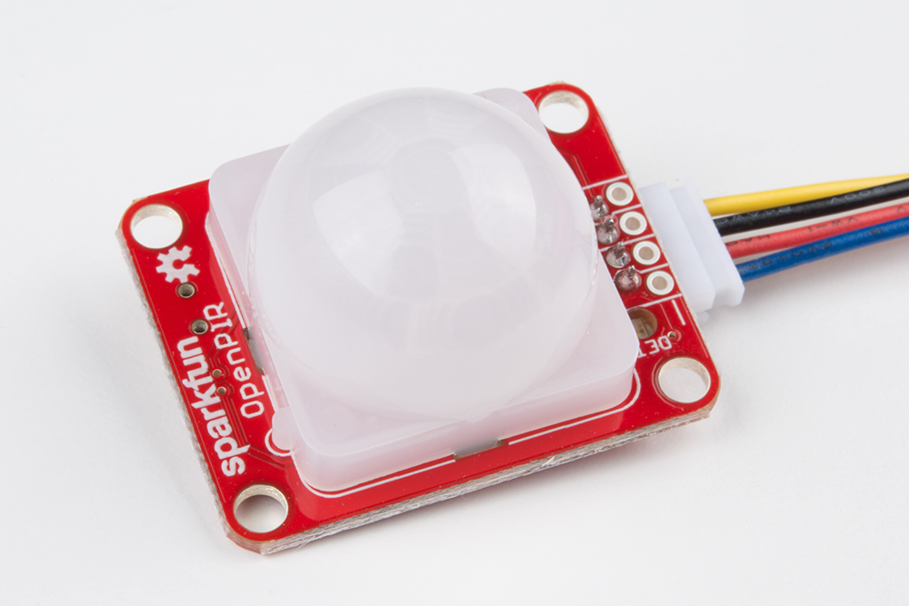
As a bonus, plugging our 4-wire JST cable assembly into the OpenPIR will logically color-code the power supply pins --- VCC on red, GND on black, OUT on yellow, and the analog output connected to blue.