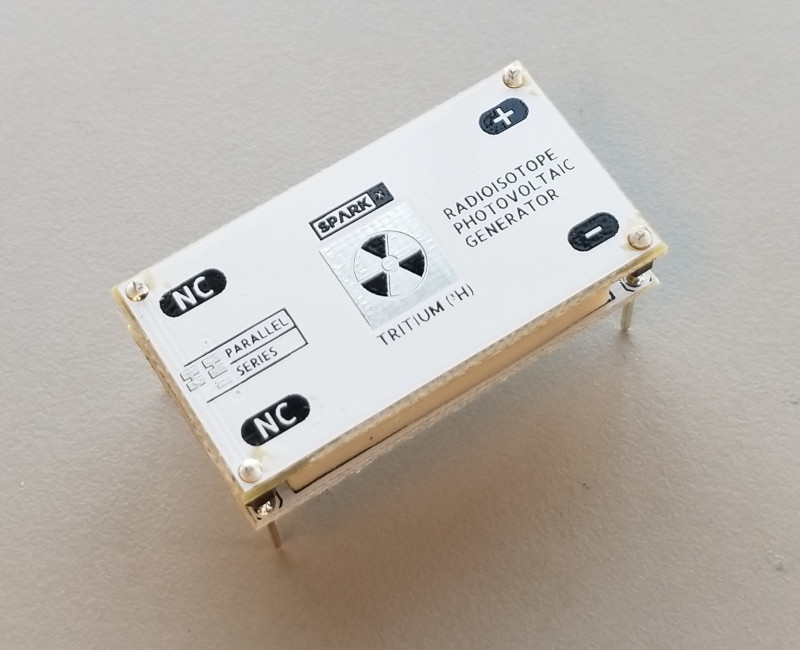
Nuclear Battery Assembly Guide
 Nick Poole
Some Assembly Required
Hardware Overview
Before beginning the assembly, let's talk a little bit more about what's included in your Nuclear Battery Kit. Each kit includes the following:
- Top and Bottom PCB with Amorphous Silicon PV Cells. These will harness the energy produced from the tritium vials.

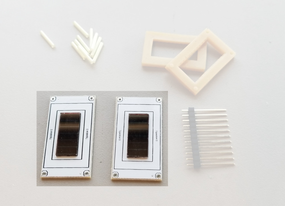
- Two Silicone Rubber Gaskets. These will hold the vials in place and help keep them safe.
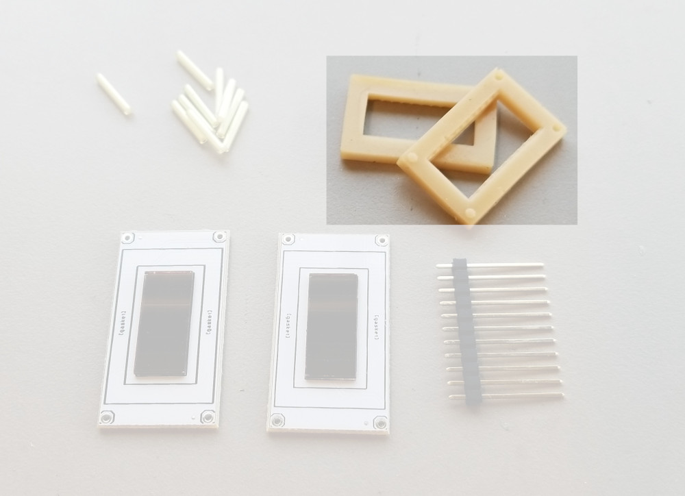
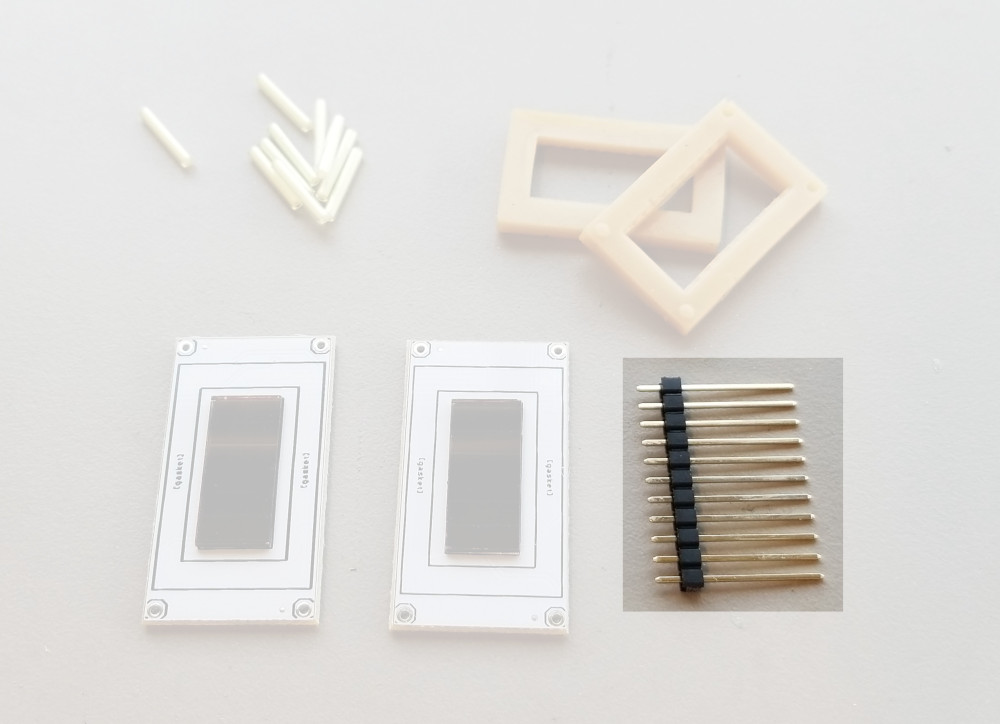
- Strip of Long Breakaway Headers. Just add some solder and these headers will bridge the two boards!
Step 1 - Gather Materials
Grab ten 2x12mm tritium gas tubes, the contents of your kit, the various tools we talked about earlier, and a breadboard (optional). And don't forget about the soft cloth! It's not a bad idea to polish the PV cells and maybe your tritium vials just to remove any smudges or dust that could effect the efficiency of the battery.

Step 2 - Attach Headers to the Top PCB
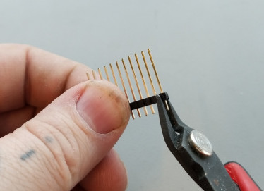
Use your pliers to break off a few individual headers. You really just need four of them, but they sometimes get bent or don't break off cleanly so we tossed in a bunch just to be safe.
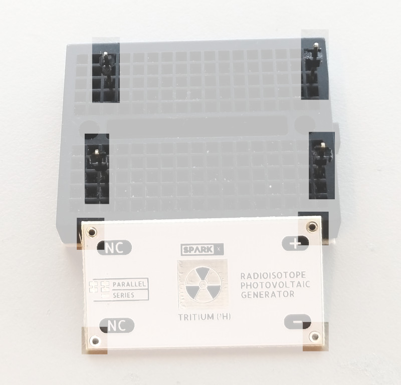
This next part is easier if you have a breadboard to hold the pins in place while you work, but you can manage without one. In the picture below, I've stuck the pin headers into my breadboard long-side-down in preparation to solder them to my top PCB. You can tell which one is the top because it will have the SparkX logo as well as some solder jumpers on the side opposite the PV cell.
Now simply solder each pin into place with a generous solder joint:
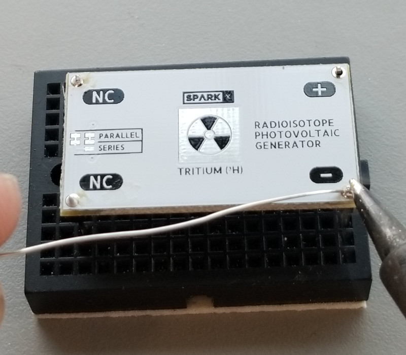
You can now remove your soldered assembly and flip it upside-down in preparation for the next step.
Step 3 - Make the Stack
Now you need to grab one of the silicone rubber gaskets. It doesn't matter which one because they're identical. Place it with the flat side down and the pips facing up in the area marked "gasket" on the PCB.

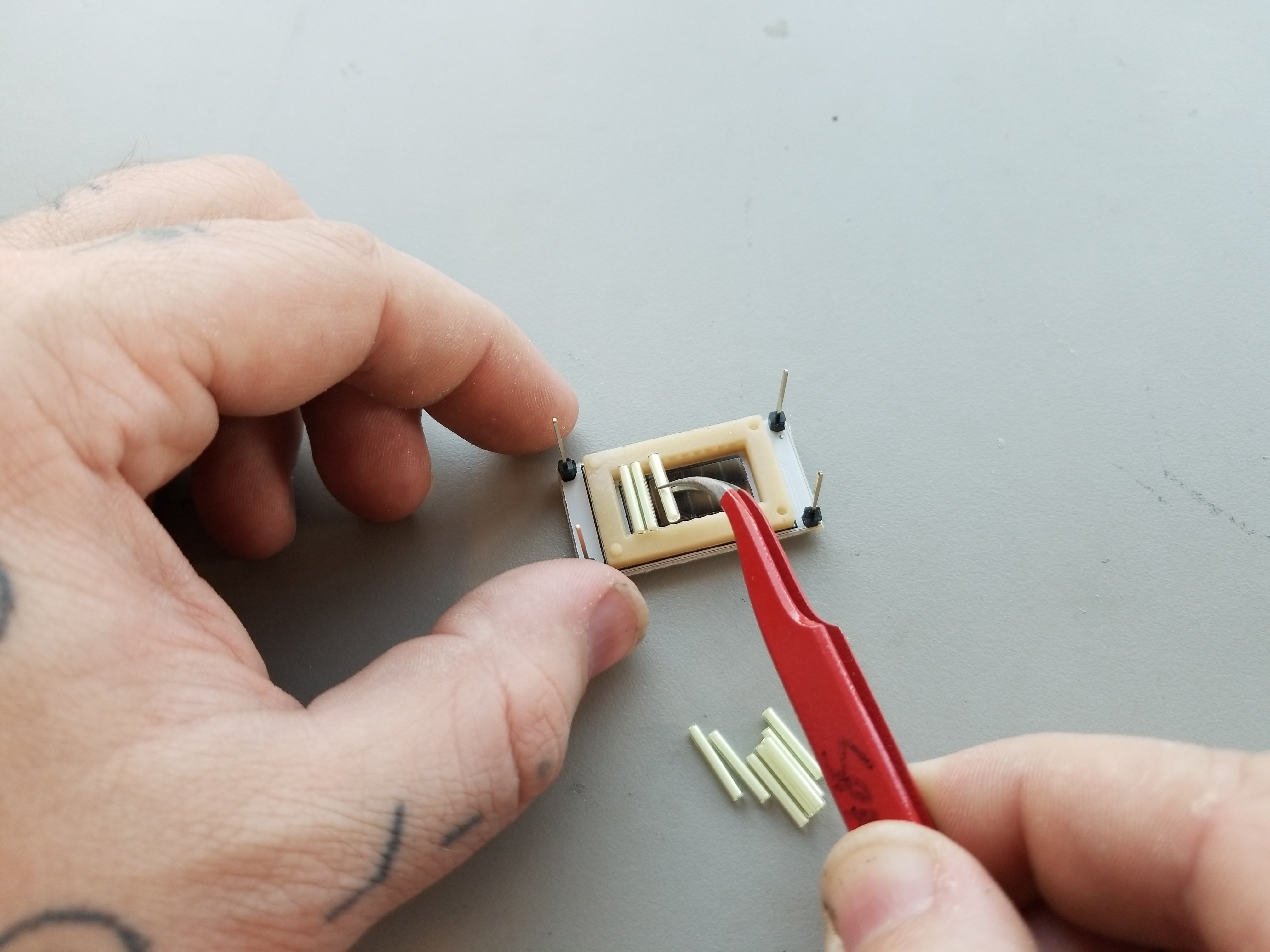
This step can be a little finicky, but take your time and use the tweezers if you need to. Place each of the 10x Tritium gas tubes into the rubber gasket. It helps to start at one end and move across. Place one end of each tube gently into a ridge on one side of the gasket and then gently press down until the other side slides into its corresponding ridge.
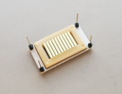
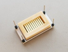
After all of the tubes are in place, you can press on them gently with a flat object to make sure they're seated. They should look like this:
Now cap the tubes with the other rubber gasket, being sure to align the holes and pips so that they mate together.
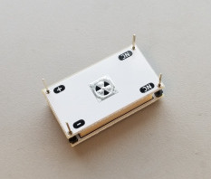
Finally, you can slide the bottom PCB onto the stack. Careful! Make sure that the board is oriented correctly. The "NC," "+," and "--" pin labels on both boards should line up!
Step 4 - Solder It All Together
For this step, you'll want to apply some clamping force to the stack. Too much force will deform the rubber gaskets, causing the tubes to rattle loose in the assembly. In this case, you will need to re-build your stack. A small weight or a very weak binder clip should work, but I find masking tape is also acceptable.

Now solder each of the four pins, these provide both the electrical connection between the PV cells and the mechanical connection which holds the generator together. DO NOT clip the headers after soldering as they will act as the leads for your battery.

Once you're finished soldering, your battery is complete!