Nuclear Battery Assembly Guide
 Nick Poole
 A Healthy Green Glow
Experimental Products: SparkX products are rapidly produced to bring you the most cutting edge technology as it becomes available. These products are tested but come with no guarantees. Live technical support is not available for SparkX products.
We were inspired to develop the Nuclear Battery Kit after finding some very cool folks making their very own homemade nuclear batteries. The following assembly guide will take you through the construction of this project step by step and even discuss some of the chemistry that makes nuclear batteries possible!
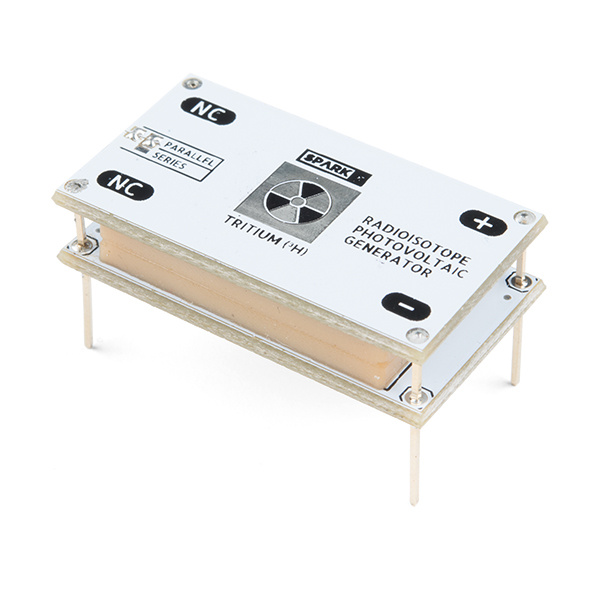
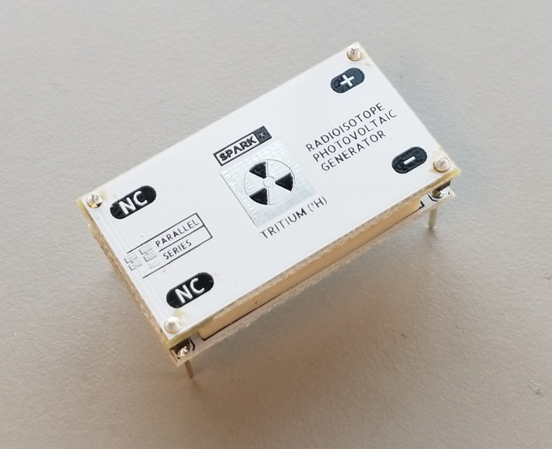
These devices are actually known as "Radioisotope Photovoltaic Generators" or "Photobetavoltaic Generators," and they're a pretty clever design: glowing glass pills filled with tritium gas and coated in a phosphorescent material are sandwiched between two photovoltaic cells. The beta radiation emitted by the tritium is blocked by the glass walls of the pill, but they cause the phosphorescent coating to glow. This light has no trouble passing through the glass and lands on the photovoltaic cells where it produces a small amount of electricity!
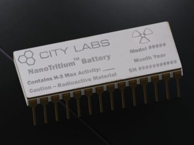
Commercial tritium batteries — like those produced by City Labs — cut out the middleman by using betavoltaic (as opposed to photovoltaic) cells in direct contact with tritium gas. Those commercial devices are more rugged and efficient, but come with a very large price tag (thousands of USD per unit).

On the other hand, homemade devices constructed using the packing tape sandwich method are as cheap as it gets, but aren't particularly sturdy.
This kit provides a good compromise between price and quality of construction. We've designed carrier boards for both of the photovoltaic cells which we supply pre-soldered and fixed to the boards with chipbonder. We have also designed and cast custom silicone rubber grommets which cushion the tritium vials between the two photovoltaic cells, preventing the cells from getting scratched or chipped and — most importantly — the vials from getting broken. The carrier boards also allow you to choose whether the photovoltaic cells are wired in series or parallel and provide you with breadboard compatible pin spacing for the battery terminals.
Required Materials
Now that we've explained the science behind this kit, it's time to start on the construction. To create nuclear batteries of your own, you will need the following materials in addition to the tritium that must be purchased elsewhere:

The breadboard is not needed for this project but it will simplify the required soldering. For information on finding and purchasing tritium vials, please reference the next section "A Brief Word on Tritium Gas Lights." You will need at least ten vials for this guide.
Tools
You will also need some basic soldering equipment and a couple simple tools. The following products are a great starting point:


Weller WLC100 Soldering Station
TOL-14228Please note the tweezers and pliers are not required but will make the construction process easier. In addition, a soft cloth is recommended for cleaning various components of the kit and masking tape may be useful in keeping parts of the battery stationary during the assembly.
Suggested Reading
If you're new to soldering or want to brush up on your soldering skills before beginning this project, please check out the following tutorial:
How to Solder: Through-Hole Soldering
A Brief Word on Tritium Gas Lights
Before you get started, you'll need to get your hands on some 2x12mm Tritium glow vials.
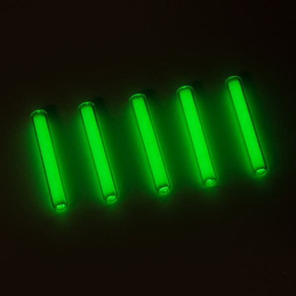
Remember that you will need 10x of them. These are sold under various tradenames such as:
- Mixglo
- DaxLight
- BETALight
- Gaseous Tritium Light Source (GTLS)
- Tritium Glow Tube
- Tritium Gas Tube
- Tritium Glow Vial
They're easily found on sites such as ebay, banggood, aliexpress, etc. as well as certain specialty websites. Although their sale is regulated in many countries — and you should be aware of your local laws before attempting to procure any radioisotope — we didn't have any trouble mail-ordering a small number of them in the US.
These Tritium Glow Tubes are perfectly safe to handle as the beta radiation generated from the Tritium decay cannot pass through the glass wall of the vial. Incidentally, the collision of the beta particles with the glass does produce a very tiny amount of x-rays, but not enough to harm anything. The only danger associated with Tritium gas is if it is inhaled, injected, or otherwise inserted into the body, which can only happen if you break the glass vial. If a vial does break, evacuate the room for a while to allow the gas to dissipate. Tritium occurs naturally in very small quantities and has a very short half-life compared with other glow products (such as radium) so breaking a glow vial will not turn your home into a superfund site.
If you'd like to learn more about Tritium Glow Tubes, you can check out this excellent blog post on how they're made and how they're used in watchmaking!
Some Assembly Required
Hardware Overview
Before beginning the assembly, let's talk a little bit more about what's included in your Nuclear Battery Kit. Each kit includes the following:
- Top and Bottom PCB with Amorphous Silicon PV Cells. These will harness the energy produced from the tritium vials.

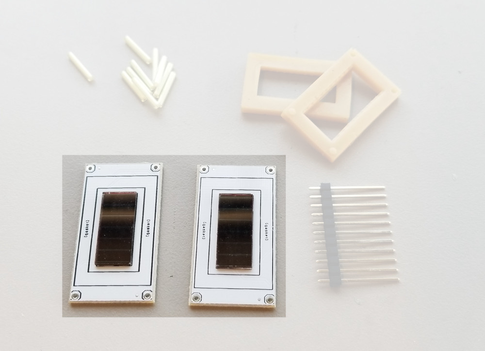
- Two Silicone Rubber Gaskets. These will hold the vials in place and help keep them safe.
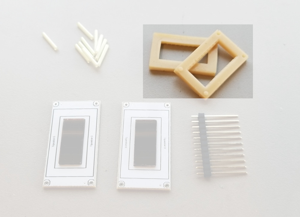
- Strip of Long Breakaway Headers. Just add some solder and these headers will bridge the two boards!
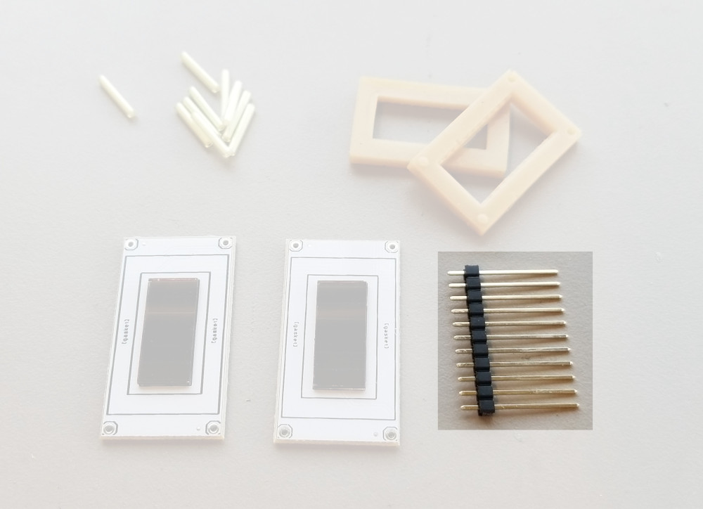
Step 1 - Gather Materials
Grab ten 2x12mm tritium gas tubes, the contents of your kit, the various tools we talked about earlier, and a breadboard (optional). And don't forget about the soft cloth! It's not a bad idea to polish the PV cells and maybe your tritium vials just to remove any smudges or dust that could effect the efficiency of the battery.

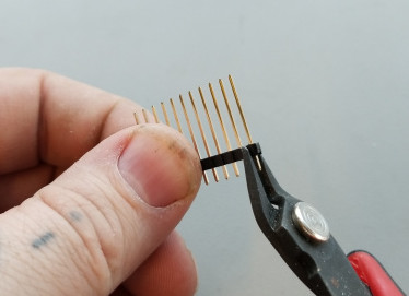
Step 2 - Attach Headers to the Top PCB
Use your pliers to break off a few individual headers. You really just need four of them, but they sometimes get bent or don't break off cleanly so we tossed in a bunch just to be safe.
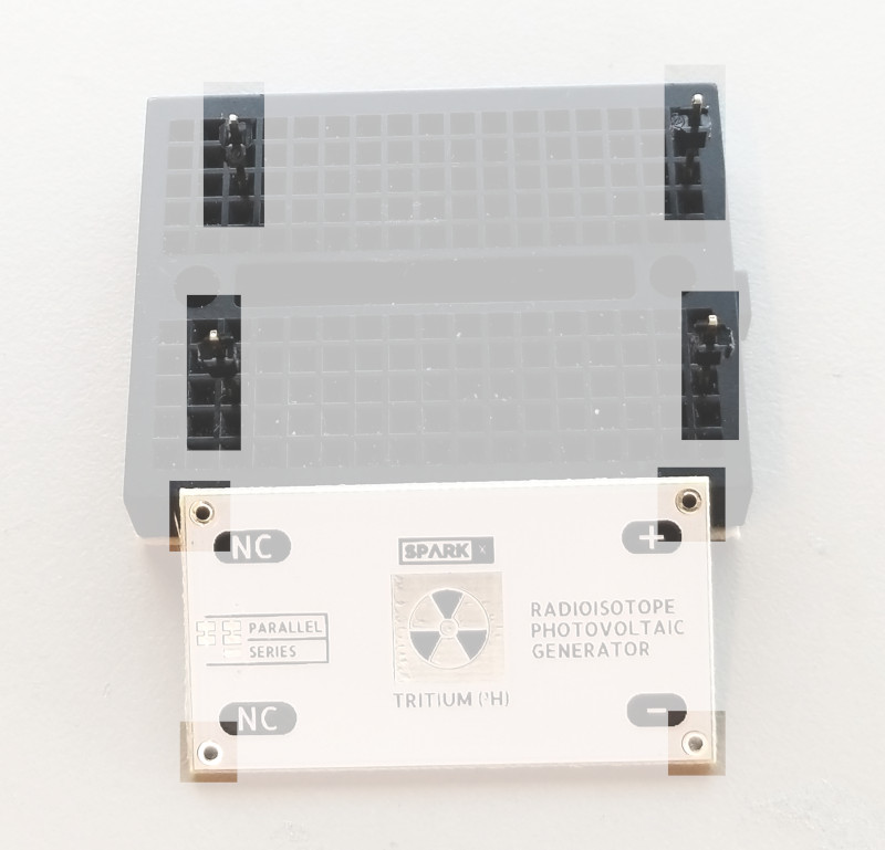
This next part is easier if you have a breadboard to hold the pins in place while you work, but you can manage without one. In the picture below, I've stuck the pin headers into my breadboard long-side-down in preparation to solder them to my top PCB. You can tell which one is the top because it will have the SparkX logo as well as some solder jumpers on the side opposite the PV cell.
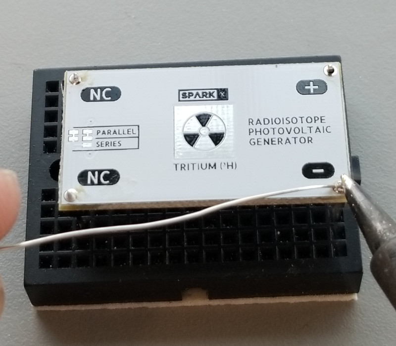
Now simply solder each pin into place with a generous solder joint:
You can now remove your soldered assembly and flip it upside-down in preparation for the next step.
Step 3 - Make the Stack
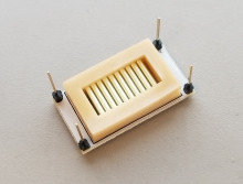
Now you need to grab one of the silicone rubber gaskets. It doesn't matter which one because they're identical. Place it with the flat side down and the pips facing up in the area marked "gasket" on the PCB.

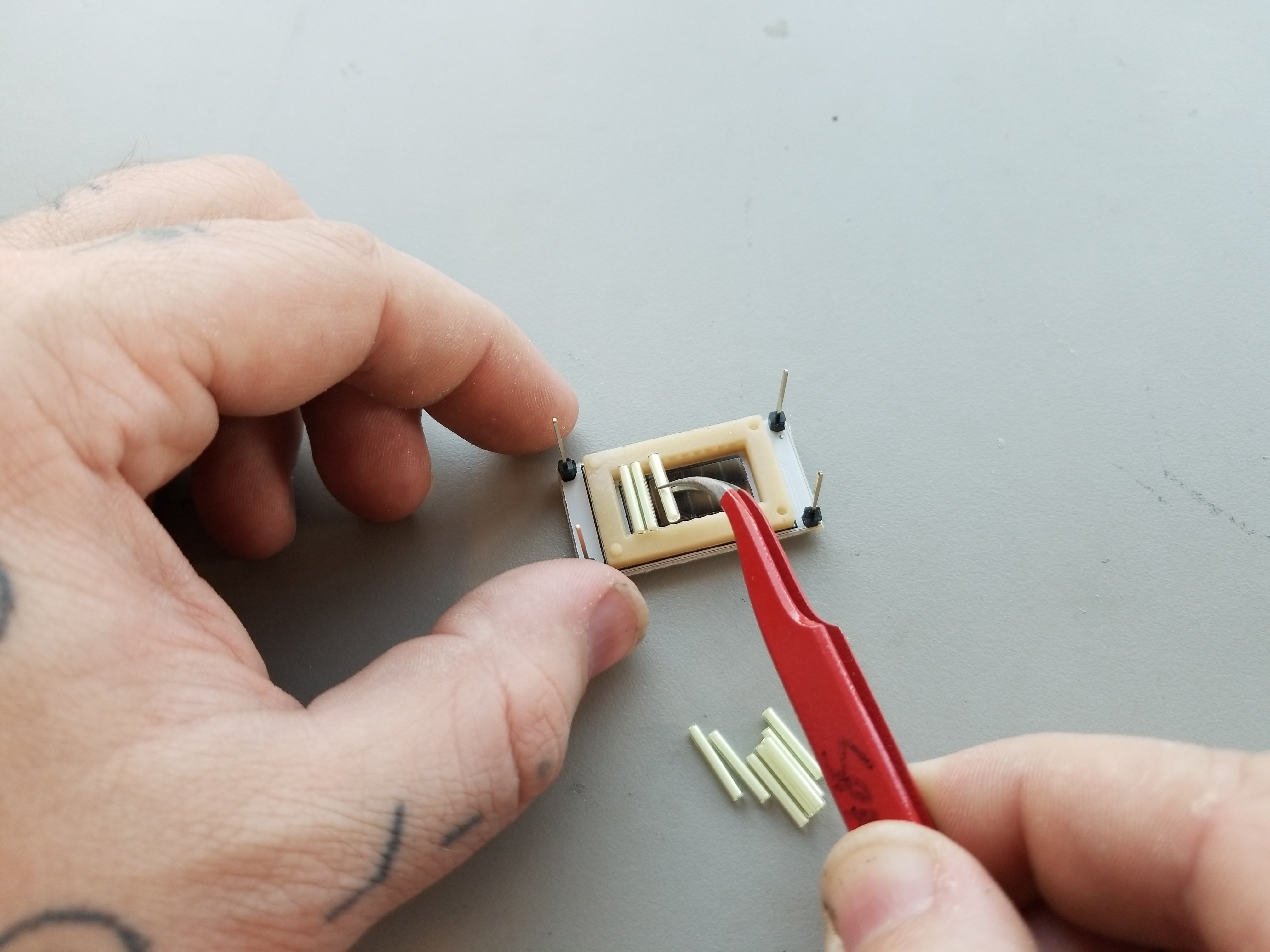
This step can be a little finicky, but take your time and use the tweezers if you need to. Place each of the 10x Tritium gas tubes into the rubber gasket. It helps to start at one end and move across. Place one end of each tube gently into a ridge on one side of the gasket and then gently press down until the other side slides into its corresponding ridge.
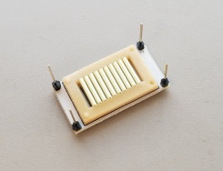
After all of the tubes are in place, you can press on them gently with a flat object to make sure they're seated. They should look like this:
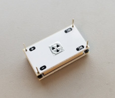
Now cap the tubes with the other rubber gasket, being sure to align the holes and pips so that they mate together.
Finally, you can slide the bottom PCB onto the stack. Careful! Make sure that the board is oriented correctly. The "NC," "+," and "--" pin labels on both boards should line up!
Step 4 - Solder It All Together
For this step, you'll want to apply some clamping force to the stack. Too much force will deform the rubber gaskets, causing the tubes to rattle loose in the assembly. In this case, you will need to re-build your stack. A small weight or a very weak binder clip should work, but I find masking tape is also acceptable.

Now solder each of the four pins, these provide both the electrical connection between the PV cells and the mechanical connection which holds the generator together. DO NOT clip the headers after soldering as they will act as the leads for your battery.

Once you're finished soldering, your battery is complete!
A Little Bit of Power
So how much power does it make? Not much. The best measurement we were able to make (using the method outlined by NurdRage) suggests that the maximum power point of this arrangement is 25nW, if you can build a circuit that loads it properly (between 20 and 30nA at about 0.6v).

Further experiments show that the battery will — given enough time — charge a capacitor to a voltage of 1.5 volts. Using this battery to do any work will likely involve a clever energy harvesting circuit, but keep in mind that this tiny amount of power will continue to flow for about 20 years — the half life of Tritium being 12 years.

Resources and Going Further
For more information, check out these pages:
- GitHub
- Hackaday: Make Your Own Nuclear Batteries
- City Labs: Nuclear Batteries
- YouTube: NurdRage - Make a Tritium Nuclear Battery or Radioisotope Photovoltaic Generator
- A Blog to Watch: A Unique Look Into How Glow-In-The-Dark Tritium Gas Tubes Are Made At MB-MICROTEC
If you ever find yourself looking for a little more power, take a look at these tutorials and hookup guides:
Connector Basics
TPL5110 Nano Power Timer Hookup Guide
Thing Plus Dual-Port Logging Shield Hookup Guide
Or if you want to learn more about radioactivity, feel free to take a look at these blog posts: