nRF52840 Advanced Development With the nRF5 SDK
 jimblom
BLE Blinky Example
Blinking an LED's fine and all, but it barely scratches the surface of the nRF52840's capabilities. How about we add some Bluetooth to the mix?
Navigate back into your nRF5 SDK's examples folder and find ble_peripheral/ble_app_blinky. Open it up just as you did the previous blinky example.
Once open, just as with the last example, duplicate the pca10056 folder and rename the new folder sparkfun_nrf52840_mini.
And, you guessed it, you'll need to modify the "Makefile" and "blinky_gcc_nrf52.ld" files in "sparkfun_nrf52840_mini/s140/armgcc" to add a "bootload" target, and to modify the Flash origin/size. In the linker, "ld," file only modify the FLASH size, leave the RAM alone.
One last modification I'd recommend making is to the main.c file at the top of the directory. This is the main source file that manages all of the configuration and initialization. Towards the top of the file -- beginning around line 72 -- are LED pin definitions. I recommend setting each of the LED definitions to BSP_BOARD_LED_0. You can also set the BLE device name if you'd like. That section would end up looking something like this:
language:c
#define ADVERTISING_LED                 BSP_BOARD_LED_0                         /**< Is on when device is advertising. */
#define CONNECTED_LED                   BSP_BOARD_LED_0                         /**< Is on when device has connected. */
#define LEDBUTTON_LED                   BSP_BOARD_LED_0                         /**< LED to be toggled with the help of the LED Button Service. */
#define LEDBUTTON_BUTTON                BSP_BUTTON_0                            /**< Button that will trigger the notification event with the LED Button Service */

#define DEVICE_NAME                     "SparkFun_nRF52840"                         /**< Name of device. Will be included in the advertising data. */
Setting each LED to BSP_BOARD_LED_0 kind of abuses the code, but we do what we can with a single on-board LED. It allows us to both tell if the board is connected, and toggle the LED from the app.
Speaking of the app...
Using nRF Connect to Control the Board
To test this example sketch, you'll need another device -- either computer or smartphone -- connected to your nRF52840. Nordic provides a free, handy test tool, nRF Connect for Mobile, that's available for both Android or iOS. We'll demonstrate how to control your nRF52840's LED and monitor the button using this sketch. So go download the app!
Once downloaded, open the app and begin searching for nearby Bluetooth devices. Among those with a strong signal strength, you should see SparkFun_nRF52840. Click the "CONNECT" button next to that.
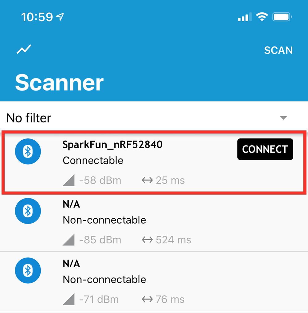
Once connected, the Blue LED should turn off indicating a connection.
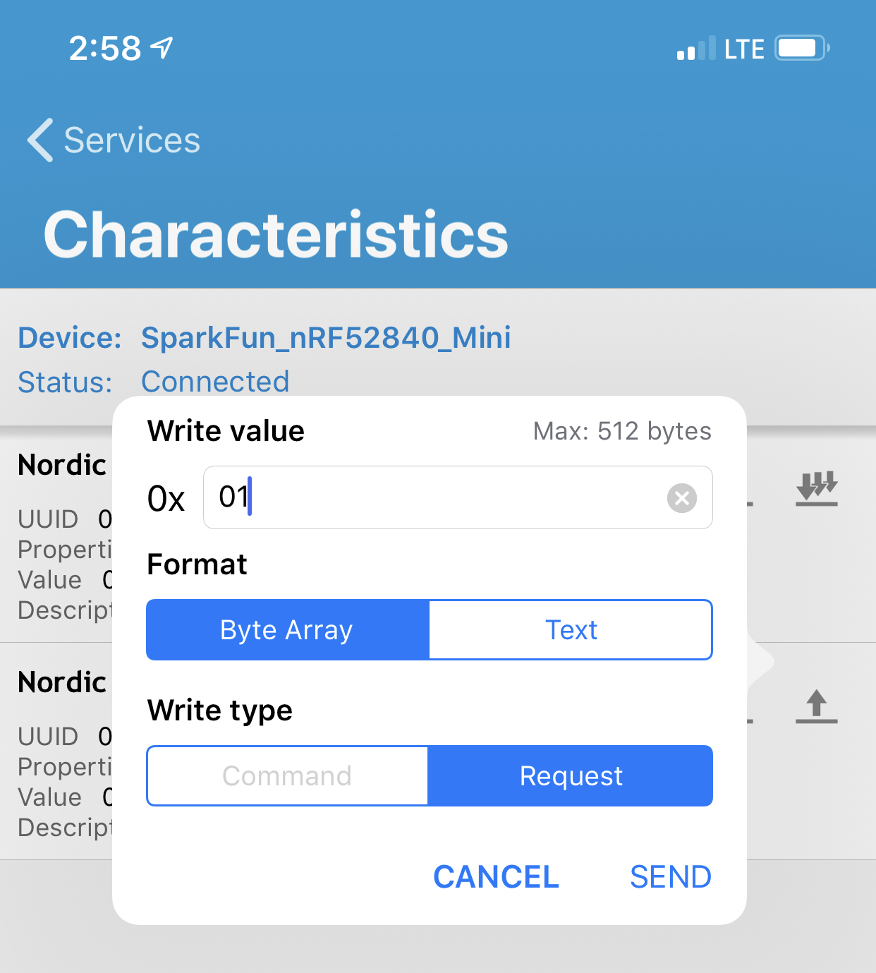
Click on the LED Button Service, where you'll be presented with a pair of characteristics: "Nordic Blinky Button" and "Nordic Blinky LED."
To set the LED, click on the up-arrow in the Nordic Blinky LED characteristic. To turn the LED on, type 01 into the value text box. To turn it off, type 00 (note the double-zero).
To read the status of the button on pin 13, either tap single-down-arrow for a single read, or subscribe to notifications by tapping the triple-down-arrow. When you press the button down, the value should change to 0x01.