MP3 Trigger Hookup Guide V24
 Joel_E_B,
  robertsonics
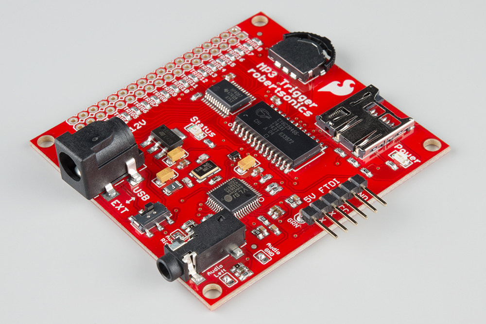
 Board Overview
Here is a brief overview of the MP3 Trigger's specifications:
Specifications
- Input Voltage Range: 4.5V to 12.0V DC, or regulated 3.3V (jumper selectable)
- Current Consumption: Approximately 45mA idle, 85mA playing
- Media: SDSC and SDHC microSD cards
- File system: FAT32 and FAT16
- Audio output: Headphone stereo (1/8” stereo jack)
- Trigger inputs: Logic level 3.3V–5.0V, active low inputs, w/ internal pull-ups (connector provides individual grounds, allowing switches or jumpers to be connected directly to each trigger input)
- Serial: Full duplex, 8-bit, 38.4Kbaud (default, other baud rates supported via initialization file)
The following will highlight the various hardware sections found on the MP3 Trigger.
Power
The MP3 Trigger is designed to be powered a few different ways.
External Power via Barrel Jack
The first and most obvious power scheme is to apply external power to the barrel jack connector (5.5x2.1mm center positive). As the silkscreen next to the connector reads, you may power the MP3 Trigger through this jack with 4.5-12V DC.
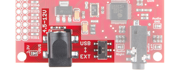
The solder jumper next to the barrel jack comes set to VBUS by default. Ensure that this jumper is always set to VBUS so long as you're powering the MP3 Trigger through that connector.
While power is applied to the barrel jack, you may use the USB/EXT switch as an ON/OFF switch to control the power to the MP3 Trigger. It should be powered while in the EXT position.

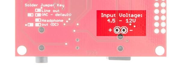
External Power via Through Holes
You can also solder power wires directly to the through-holes located on the backside of the board.
FTDI Header via 5V Power Source
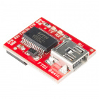
If you would like to integrate the MP3 Trigger into an existing system that uses 5V (like a USB port), you can power the MP3 Trigger through the FTDI header.

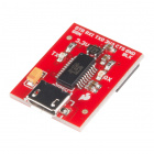
You can apply the regulated power source directly to the VCC and GND pins, or you can solder some right-angle headers to the FTDI port and power with the appropriate 5V FTDI Basic Breakout.
 |
 |
| Right-Angle Headers Soldered on FTDI Port | Power with 5V FTDI |
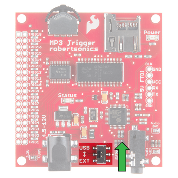
Once connected, flip the switch to the USB side to power the board.

If you intend on using the MP3 Trigger in conjunction with an Arduino or other microcontroller to communicate over the UART, you will do so through this port as well.
Why Use a 5V FTDI and Not a 3.3V FTDI?
You may not be able to power the MP3 Trigger with a 3.3V power source via the FTDI header despite it seeming logical that you could use a 3.3V FTDI on the "5V FTDI" header. The reasoning behind this is that certain versions of the 3.3V FTDI Basic uses the FTDI IC to regulate 5V down to 3.3V. If you are using this device to power the MP3 Trigger, you may exceed the current limitation of the 3.3V FTDI, leading to a potential brown-out on your device. Thus, we recommend using a 5V FTDI Basic.
FTDI Header via Regulated 3.3V Power Source
If you power the MP3 Trigger with a regulated 3.3V power source that is able to source enough current via FTDI header's VCC pin, you will need to clear the solder jumper and resolder it so that the 3.3V pad and center pad are connected before you can power the board.
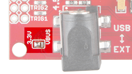
Once connected with a regulated 3.3V power source on the FTDI header, flip the switch to the USB side to power the board.
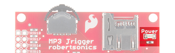
Power LED
Power is indicated by the red Power LED located in the upper-right corner.
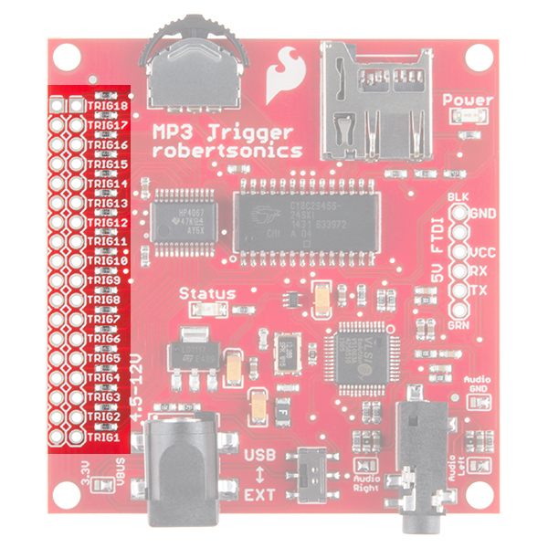
Trigger Pins
The Trigger pins are what make the MP3 Trigger so easy to use. Each of the 18 triggers is broken out to a 0.1" through-hole. Next to each trigger pin is a ground pin. By shorting a trigger pin to ground, you are activating that trigger and thus playing the audio file associated with that particular trigger. More information can be found in the Using the Trigger Inputs section.
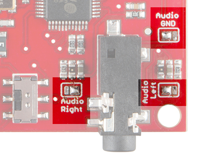
1/8" Stereo Headphone Jack and Audio Solder Jumpers
The MP3 Trigger has a 1/8" (3.5mm) audio jack to connect your project to an amplifier and speakers or to headphones.
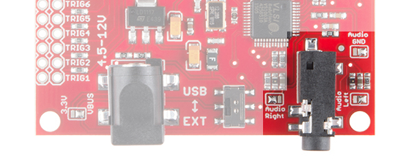
You will only be able to have your MP3 Trigger configured to play audio as a line out or as headphones,** but not both at the same time**. By default, the MP3 Trigger comes configured to play over a line out to an external audio system. If you wish to use your MP3 Trigger with headphone instead, you'll need to clear the solder from all three audio solder jumpers and solder the center pads to the opposite pads.
A solder jumper cheat sheet is conveniently printed in the silkscreen on the back of the MP3 Trigger to help you in altering the audio configuration.
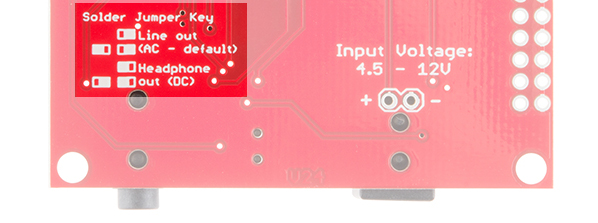
Once configured for headphones, the jumpers should look like this:
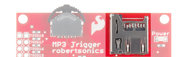
Navigation Switch
The navigation switch allows you to cycle through and play/stop all the tracks located on your microSD card. More information on its operation can be found in the Basic Operation Section.
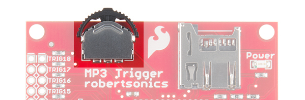
MicroSD Socket
The microSD socket is a simple push-to-insert/push-to-remove mechanism. The MP3 Trigger supports both SDSC (up to 2GB) and SDHC (up to 32GB) type microSD cards. More information on how the microSD card initializes can be found in the Basic Operation Section.