MicroMod Data Logging Carrier Board Hookup Guide
 El Duderino,
  Nate
Nate 
Hardware Assembly
Inserting the Processor Board
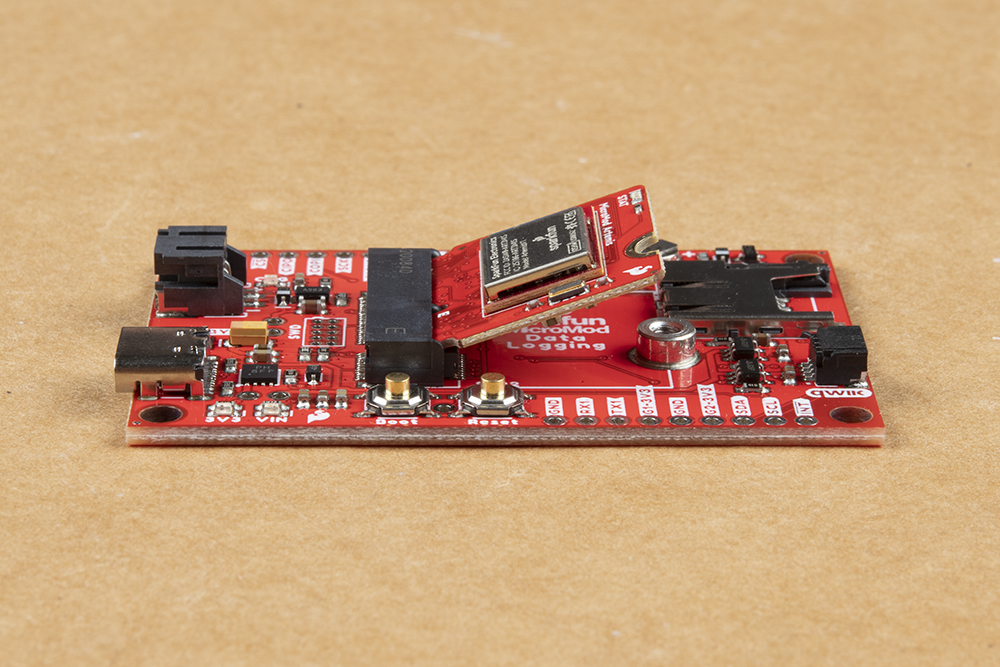
With the M.2 MicroMod connector, connecting your processor board is easy. Match up the key on your processor's beveled edge connector to the key on the M.2 connector on your Carrier Board. At a 45° angle, insert the processor board to the M.2 connector. The Processor board will stick up at an angle as seen here:
Once the board is in the socket, gently press the Processor board down, grab the set screw and tighten it with a Phillip's head screwdriver:

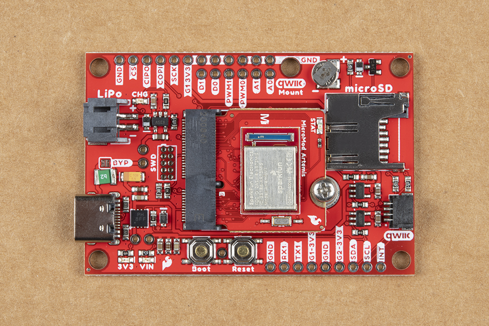
Once the Processor is secure, your assembled MicroMod system should look similar to the image below!
Data Logging Peripherals
As we mentioned previously, the Data Logging Carrier Board offers several ways to connect your sensors or other peripherals you intend to log data from.
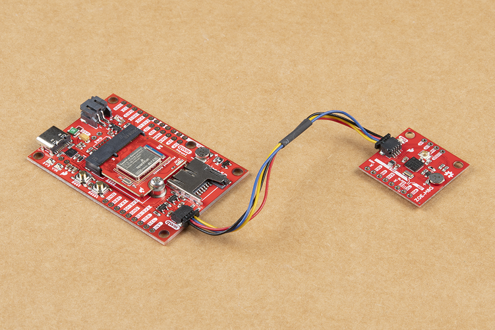
If you are using a Qwiic breakout just connect it using a Qwiic cable to the Qwiic connector on the Carrier Board. If your I2C device is not Qwiic-enabled, you can either use a Qwiic adapter cable or connect the peripheral to the Carrier Board using the 0.1"-spaced PTH pins for I2C. Soldering is strongly recommended for this approach but if you just want a temporary connection for prototyping you can use IC Hooks like these or these.
For alternate data inputs using SPI, Serial UART or other inputs (analog, digital, etc.), you will need to connect them to the 0.1"-spaced PTH pins broken out on either side of the Data Logging Carrier Board using one of the methods covered above. Take note of which 3.3V rail you are connecting them to for easy reference when controlling power to your devices after everything is soldered together.
Before powering everything up, insert your microSD card into the card slot and press it in to lock it into place.
Connecting Everything Up
With your processor inserted and secured it's time to connect your MicroMod Data Logging Carrier Board to your computer using the USB-C connector. Depending on which Processor you choose and which drivers you already have installed, you may need to install drivers for your processor board. Refer to your Processor Board's Hookup Guide for detailed instructions on how to install them. At this point you can also connect your battery for charging or to power the circuit once USB power is removed.

For this particular tutorial, we are using the Artemis MicroMod Processor. Board definitions for this processor board can be found in the Software Setup and Programming section of the Artemis MicroMod Processor Board Hookup Guide.
If you are using a different processor board, go to our MicroMod Processor Boards landing page, find your processor board, and head on over to that tutorial for help installing your board definition.