$17.50
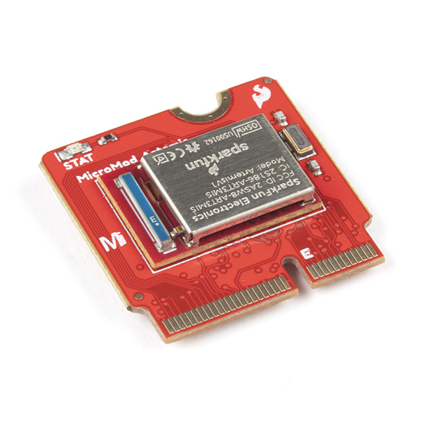
Leveraging the ultra powerful Artemis Module, the SparkFun MicroMod Artemis Processor is the brain board of your dreams. With a Cortex-M4F with BLE 5.0 running up to 96MHz and with as low power as 6uA per MHz (less than 5mW), the M.2 MicroMod connector allows you to plug in a MicroMod Carrier Board with any number of peripherals. Let's have a look at what this processor board has to offer!
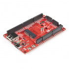
In addition to your MicroMod Artemis Processor Board, you'll need a carrier board to get started. Here we use the Machine Learning Carrier Board, but there are a number of others you can choose from.
You'll also need a USB-C cable to connect the Carrier to your computer and if you want to add some Qwiic breakouts to your MicroMod project you'll want at least one Qwiic cable to connect it all together. Below are some options for both of those cables:
Depending on which Carrier Board you choose, you may need a few extra peripherals to take full advantage of them. Refer to the Carrier Boards' respective Hookup Guides for specific peripheral recommendations.
The SparkFun MicroMod ecosystem is a unique way to allow users to customize their project to their needs. Do you want to send your weather data via a wireless signal (eg. Bluetooth or WiFi)? There's a MicroMod processor for that. Looking to instead maximize efficiency and processing power? You guessed it, there's a MicroMod processor for that. If you are not familiar with the MicroMod system, take a look here:
| MicroMod Ecosystem |
We also recommend taking a look through the following tutorials if you are not familiar with the concepts covered in them:
While the Artemis module is pretty self-contained, let's have a look at a few of the unique features of this MicroMod Processor Board.
Power is supplied by the carrier board, but it should be noted that all pins are 3.3V.
All of our MicroMod Processor boards come equipped with the M.2 MicroMod Connector, which leverages the M.2 standard and specification to allow you to install your MicroMod Processor board on your choice of carrier board.
 |
 |
| M.2 Connector from the Front | M.2 Connector from the Back |
The SparkFun Artemis Processor provides a Cortex-M4F with BLE 5.0 running up to 96MHz and with as low power as 6uA per MHz (less than 5mW). This module is powerful enough to run TensorFlow, Machine Learning, and all sorts of voice recognition software. A deep dive into all of Artemis's delightful features can be found in the Designing with the SparkFun Artemis tutorial.
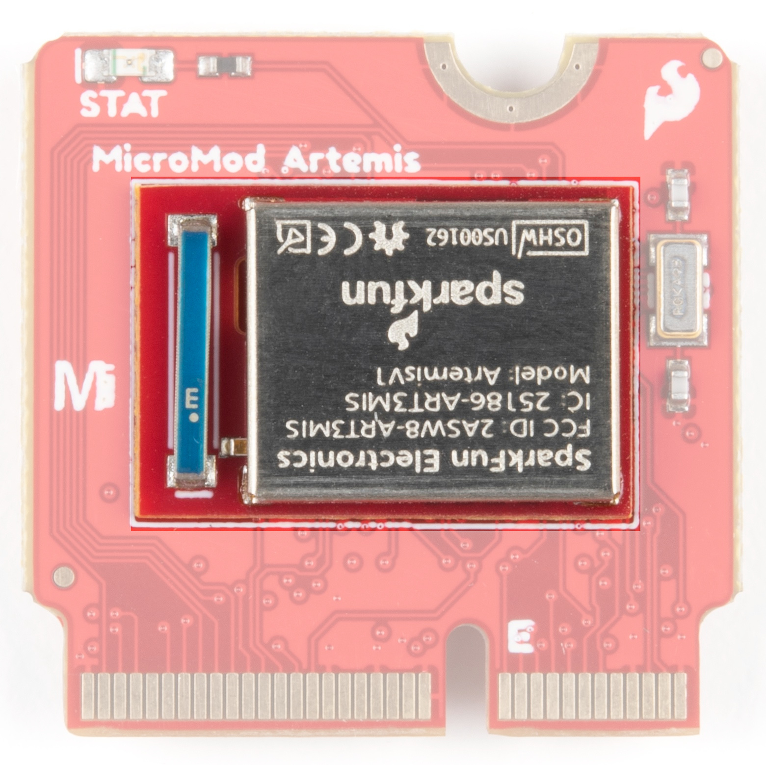
Incoming analog voltages over 2V will saturate the Artemis's analog to digital converter. We've integrated an OpAmp to scale the incoming 0-3.3V voltages down to the 0-2V range that the Artemis can handle.

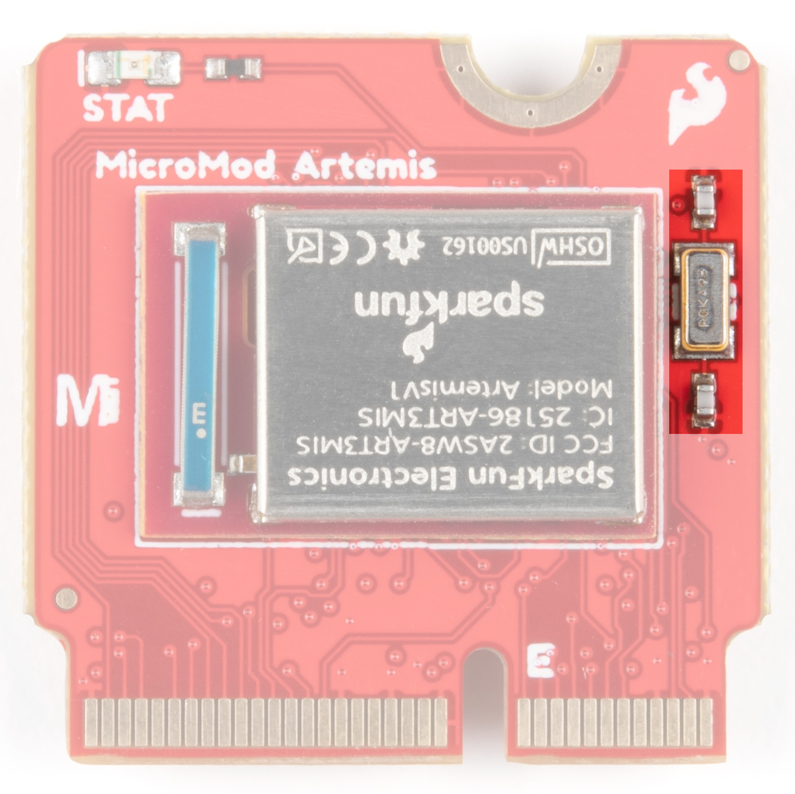
An onboard RTC crystal has been integrated.
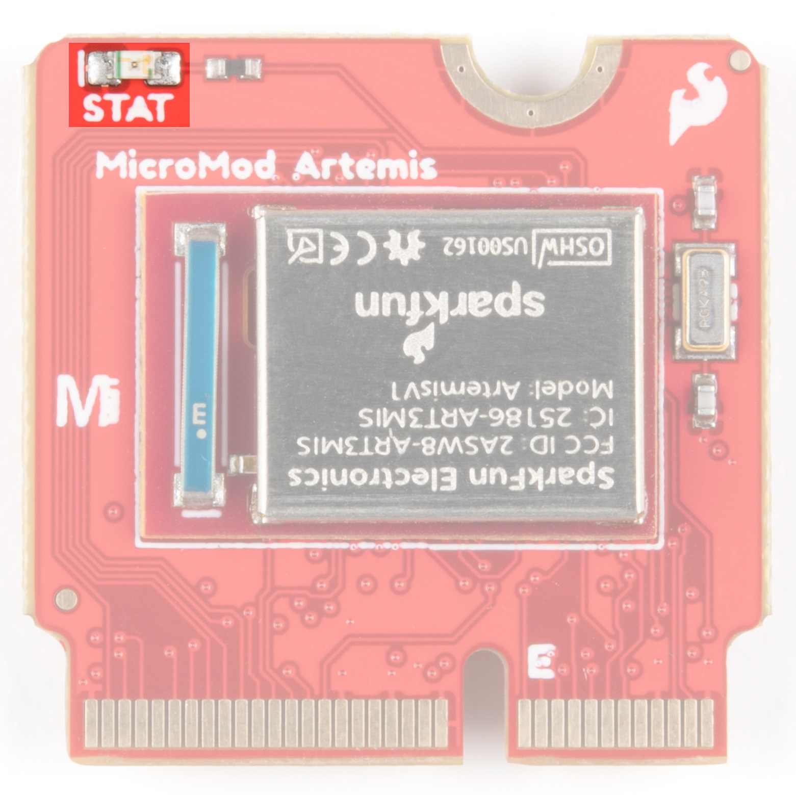
We've also included a Status LED for all your blinky needs.
| AUDIO | UART | GPIO/BUS | I2C | SDIO | SPI | Dedicated |
| Function | Bottom Pin |
Top Pin |
Function | ||||||
|---|---|---|---|---|---|---|---|---|---|
| (Not Connected) | 75 | GND | |||||||
| 3.3V | 74 | 73 | G5 / BUS5 | ||||||
| RTC_3V_BATT | 72 | 71 | G6 / BUS6 | ||||||
| SPI_CS1# | SDIO_DATA3 (I/O) | 70 | 69 | G7 / BUS7 | |||||
| SDIO_DATA2 (I/O) | 68 | 67 | G8 | ||||||
| SDIO_DATA1 (I/O) | 66 | 65 | G9 | ADC_D- | CAM_HSYNC | ||||
| SPI_CIPO1 | SDIO_DATA0 (I/O) | 64 | 63 | G10 | ADC_D+ | CAM_VSYNC | |||
| SPI COPI1 | SDIO_CMD (I/O) | 62 | 61 | SPI_CIPO (I) | |||||
| SPI SCK1 | SDIO_SCK (O) | 60 | 59 | SPI_COPI (O) | LED_DAT | ||||
| AUD_MCLK (O) | 58 | 57 | SPI_SCK (O) | LED_CLK | |||||
| CAM_MCLK | PCM_OUT | I2S_OUT | AUD_OUT | 56 | 55 | SPI_CS# | |||
| CAM_PCLK | PCM_IN | I2S_IN | AUD_IN | 54 | 53 | I2C_SCL1 (I/O) | |||
| PDM_DATA | PCM_SYNC | I2S_WS | AUD_LRCLK | 52 | 51 | I2C_SDA1 (I/O) | |||
| PDM_CLK | PCM_CLK | I2S_SCK | AUD_BCLK | 50 | 49 | BATT_VIN / 3 (I - ADC) (0 to 3.3V) | |||
| G4 / BUS4 | 48 | 47 | PWM1 | ||||||
| G3 / BUS3 | 46 | 45 | GND | ||||||
| G2 / BUS2 | 44 | 43 | CAN_TX | ||||||
| G1 / BUS1 | 42 | 41 | CAN_RX | ||||||
| G0 / BUS0 | 40 | 39 | GND | ||||||
| A1 | 38 | 37 | USBHOST_D- | ||||||
| GND | 36 | 35 | USBHOST_D+ | ||||||
| A0 | 34 | 33 | GND | ||||||
| PWM0 | 32 | 31 | Module Key | ||||||
| Module Key | 30 | 29 | Module Key | ||||||
| Module Key | 28 | 27 | Module Key | ||||||
| Module Key | 26 | 25 | Module Key | ||||||
| Module Key | 24 | 23 | SWDIO | ||||||
| UART_TX2 (O) | 22 | 21 | SWDCK | ||||||
| UART_RX2 (I) | 20 | 19 | UART_RX1 (I) | ||||||
| CAM_TRIG | D1 | 18 | 17 | UART_TX1 (0) | |||||
| I2C_INT# | 16 | 15 | UART_CTS1 (I) | ||||||
| I2C_SCL (I/0) | 14 | 13 | UART_RTS1 (O) | ||||||
| I2C_SDA (I/0) | 12 | 11 | BOOT (I - Open Drain) | ||||||
| D0 | 10 | 9 | USB_VIN | ||||||
| SWO | G11 | 8 | 7 | GND | |||||
| RESET# (I - Open Drain) | 6 | 5 | USB_D- | ||||||
| 3.3V_EN | 4 | 3 | USB_D+ | ||||||
| 3.3V | 2 | 1 | GND | ||||||
| Artemis Pin |
Alternate Function |
Primary Function |
Bottom Pin |
Top Pin |
Primary Function |
Alternate Function |
Artemis Pin |
|---|---|---|---|---|---|---|---|
| (Not Connected) | 73 | G5 | A29 | ||||
| - | 72 | 71 | G6 | D14 | |||
| D23 | QSPI3 | SPI_CS1 | 70 | 69 | G7 | D15 | |
| D4 | QSPI2 | 68 | 67 | - | |||
| D26 | QSPI1 | 66 | 65 | TX1 | ADC_D- | A12 | |
| D6 | QSPI0 | SPI_CIPO1 | 64 | 63 | ADC_D+ | A13 | |
| D7 | QSPI_CS | SPI_COPI1 | 62 | 61 | SPI_CIPO | D43 | |
| D5 | QSPI_SCK | SPI_SCK1 | 60 | 59 | SPI_COPI | D38 | |
| D18 | CAM_MCLK | 58 | 57 | SPI_SCK | D42 | ||
| D18 | CAM_MCLK | 56 | 55 | SPI_CS | D41 | ||
| A11 | CAM_PCLK | 54 | 53 | SCL1 | D8 | ||
| D36 | PDM_DATA | 52 | 51 | SDA1 | D9 | ||
| D37 | PDM_CLK | 50 | 49 | BATT_VIN / 3 | A31 | ||
| D28 | G4 | 48 | 47 | PWM1 | D45 | ||
| D27 | G3 | 46 | 45 | - | |||
| A34 | G2 | 44 | 43 | - | |||
| A33 | G1 | 42 | 41 | - | |||
| A16 | G0 | 40 | 39 | GND | |||
| A35 | ADC1 | 38 | 37 | - | |||
| A32 | ADC0 | 34 | 33 | - | |||
| D44 | PWM0 | 32 | 31 | - | |||
| - | 24 | 23 | SWDIO | D21 | |||
| - | 22 | 21 | SWDCK | D20 | |||
| - | 20 | 19 | RX1 | D25 | |||
| D1 | D1 | 18 | 17 | TX1 | ADC_D- | A12 | |
| D2 | I2C_Interrupt | 16 | 15 | CTS1 | D17 | ||
| D39 | SCL | 14 | 13 | RTS1 | D10 | ||
| D40 | SDA | 12 | 11 | BOOT | |||
| D0 | D0 | 10 | 9 | - | |||
| - | 8 | 7 | GND | ||||
| RESET | 6 | 5 | USB_D- | ||||
| - | 4 | 3 | USB_D+ | ||||
| 3.3V | 2 | 1 | GND |
| Signal Group | Signal | I/O | Description | Voltage | Power | 3.3V | I | 3.3V Source | 3.3V |
|---|---|---|---|---|
| GND | Return current path | 0V | ||
| USB_VIN | I | USB VIN compliant to USB 2.0 specification. Connect to pins on processor board that require 5V for USB functionality | 4.8-5.2V | |
| RTC_3V_BATT | I | 3V provided by external coin cell or mini battery. Max draw=100μA. Connect to pins maintaining an RTC during power loss. Can be left NC. | 3V | |
| 3.3V_EN | O | Controls the carrier board's main voltage regulator. Voltage above 1V will enable 3.3V power path. | 3.3V | |
| BATT_VIN/3 | I | Carrier board raw voltage over 3. 1/3 resistor divider is implemented on carrier board. Amplify the analog signal as needed for full 0-3.3V range | 3.3V | |
| Reset | Reset | I | Input to processor. Open drain with pullup on processor board. Pulling low resets processor. | 3.3V |
| Boot | I | Input to processor. Open drain with pullup on processor board. Pulling low puts processor into special boot mode. Can be left NC. | 3.3V | |
| USB | USB_D± | I/O | USB Data ±. Differential serial data interface compliant to USB 2.0 specification. If UART is required for programming, USB± must be routed to a USB-to-serial conversion IC on the processor board. | |
| USB Host | USBHOST_D± | I/O | For processors that support USB Host Mode. USB Data±. Differential serial data interface compliant to USB 2.0 specification. Can be left NC. | |
| CAN | CAN_RX | I | CAN Bus receive data. | 3.3V |
| CAN_TX | O | CAN Bus transmit data. | 3.3V | |
| UART | UART_RX1 | I | UART receive data. | 3.3V |
| UART_TX1 | O | UART transmit data. | 3.3V | |
| UART_RTS1 | O | UART ready to send. | 3.3V | |
| UART_CTS1 | I | UART clear to send. | 3.3V | |
| UART_RX2 | I | 2nd UART receive data. | 3.3V | |
| UART_TX2 | O | 2nd UART transmit data. | 3.3V | |
| I2C | I2C_SCL | I/O | I2C clock. Open drain with pullup on carrier board. | 3.3V |
| I2C_SDA | I/O | I2C data. Open drain with pullup on carrier board | 3.3V | |
| I2C_INT# | I | Interrupt notification from carrier board to processor. Open drain with pullup on carrier board. Active LOW | 3.3V | |
| I2C_SCL1 | I/O | 2nd I2C clock. Open drain with pullup on carrier board. | 3.3V | |
| I2C_SDA1 | I/O | 2nd I2C data. Open drain with pullup on carrier board. | 3.3V | |
| SPI | SPI_COPI | O | SPI Controller Output/Peripheral Input. | 3.3V |
| SPI_CIPO | I | SPI Controller Input/Peripheral Output. | 3.3V | |
| SPI_SCK | O | SPI Clock. | 3.3V | |
| SPI_CS# | O | SPI Chip Select. Active LOW. Can be routed to GPIO if hardware CS is unused. | 3.3V | |
| SPI/SDIO | SPI_SCK1/SDIO_CLK | O | 2nd SPI Clock. Secondary use is SDIO Clock. | 3.3V |
| SPI_COPI1/SDIO_CMD | I/O | 2nd SPI Controller Output/Peripheral Input. Secondary use is SDIO command interface. | 3.3V | |
| SPI_CIPO1/SDIO_DATA0 | I/O | 2nd SPI Peripheral Input/Controller Output. Secondary use is SDIO data exchange bit 0. | 3.3V | |
| SDIO_DATA1 | I/O | SDIO data exchange bit 1. | 3.3V | |
| SDIO_DATA2 | I/O | SDIO data exchange bit 2. | 3.3V | |
| SPI_CS1/SDIO_DATA3 | I/O | 2nd SPI Chip Select. Secondary use is SDIO data exchange bit 3. | 3.3V | |
| Audio | AUD_MCLK | O | Audio master clock. | 3.3V |
| AUD_OUT/PCM_OUT/I2S_OUT/CAM_MCLK | O | Audio data output. PCM synchronous data output. I2S serial data out. Camera master clock. | 3.3V | |
| AUD_IN/PCM_IN/I2S_IN/CAM_PCLK | I | Audio data input. PCM syncrhonous data input. I2S serial data in. Camera periphperal clock. | 3.3V | |
| AUD_LRCLK/PCM_SYNC/I2S_WS/PDM_DATA | I/O | Audio left/right clock. PCM syncrhonous data SYNC. I2S word select. PDM data. | 3.3V | |
| AUD_BCLK/PCM_CLK/I2S_CLK/PDM_CLK | O | Audio bit clock. PCM clock. I2S continuous serial clock. PDM clock. | 3.3V | |
| SWD | SWDIO | I/O | Serial Wire Debug I/O. Connect if processor board supports SWD. Can be left NC. | 3.3V |
| SWDCK | I | Serial Wire Debug clock. Connect if processor board supports SWD. Can be left NC. | 3.3V | |
| ADC | A0 | I | Analog to digital converter 0. Amplify the analog signal as needed to enable full 0-3.3V range. | 3.3V |
| A1 | I | Analog to digital converter 1. Amplify the analog signal as needed to enable full 0-3.3V range. | 3.3V | |
| PWM | PWM0 | O | Pulse width modulated output 0. | 3.3V |
| PWM1 | O | Pulse width modulated output 1. | 3.3V | |
| Digital | D0 | I/O | General digital input/output pin. | 3.3V |
| D1/CAM_TRIG | I/O | General digital input/output pin. Camera trigger. | 3.3V | |
| General/Bus | G0/BUS0 | I/O | General purpose pins. Any unused processor pins should be assigned to Gx with ADC + PWM capable pins given priority (0, 1, 2, etc.) positions. The intent is to guarantee PWM, ADC and Digital Pin functionality on respective ADC/PWM/Digital pins. Gx pins do not guarantee ADC/PWM function. Alternative use is pins can support a fast read/write 8-bit or 4-bit wide bus. | 3.3V |
| G1/BUS1 | I/O | 3.3V | ||
| G2/BUS2 | I/O | 3.3V | ||
| G3/BUS3 | I/O | 3.3V | ||
| G4/BUS4 | I/O | 3.3V | ||
| G5/BUS5 | I/O | 3.3V | ||
| G6/BUS6 | I/O | 3.3V | ||
| G7/BUS7 | I/O | 3.3V | ||
| G8 | I/O | General purpose pin | 3.3V | |
| G9/ADC_D-/CAM_HSYNC | I/O | Differential ADC input if available. Camera horizontal sync. | 3.3V | |
| G10/ADC_D+/CAM_VSYNC | I/O | Differential ADC input if available. Camera vertical sync. | 3.3V | |
| G11/SWO | I/O | General purpose pin. Serial Wire Output | 3.3V |
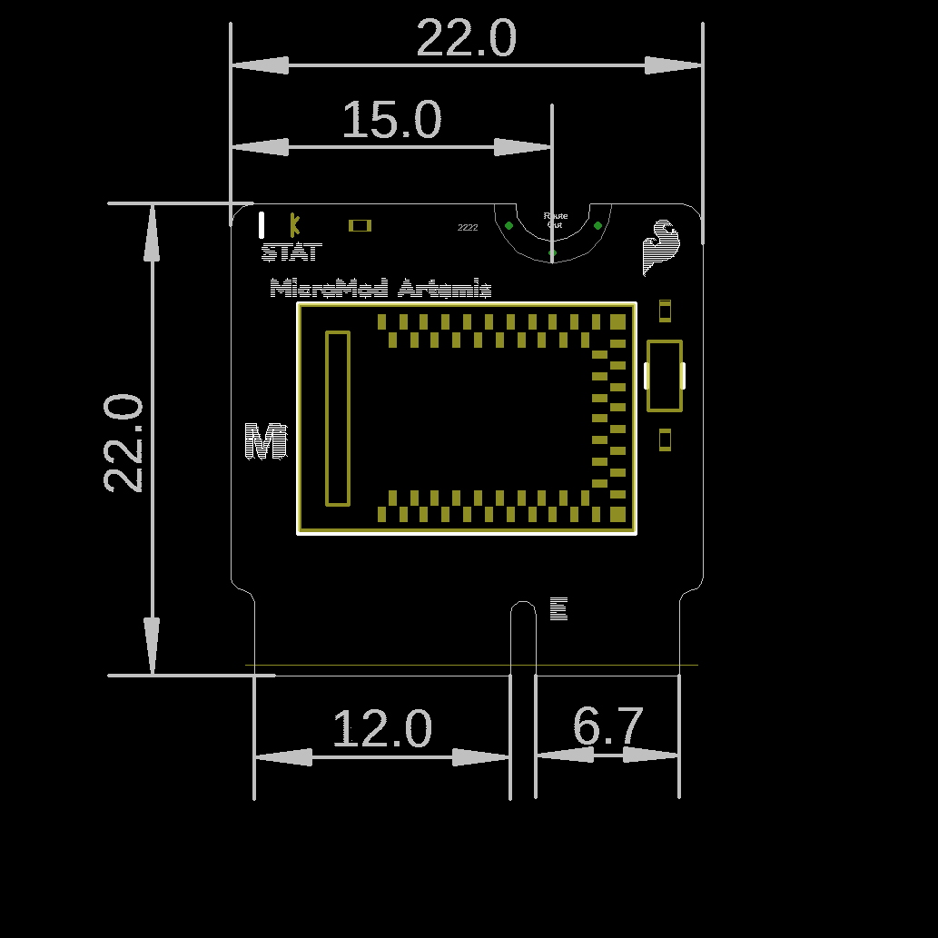
The board measures 22mm x 22mm, with 15mm to the top notch and 12mm to the E key. For more information regarding the processor board physical standards, head on over to the Getting Started with MicroMod tutorial and check out the Hardware Overview section.
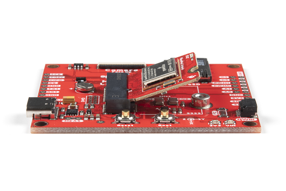
To get started with the Artemis MicroMod Processor Board, you'll need a carrier board. Here we are using the Machine Learning Carrier Board. Align the top key of the MicroMod Artemis Processor Board to the screw terminal of the Machine Learning Carrier Board and angle the board into the socket. Insert the board at an angle into the M.2 connector.

The Processor Board will stick up at an angle, as seen here:
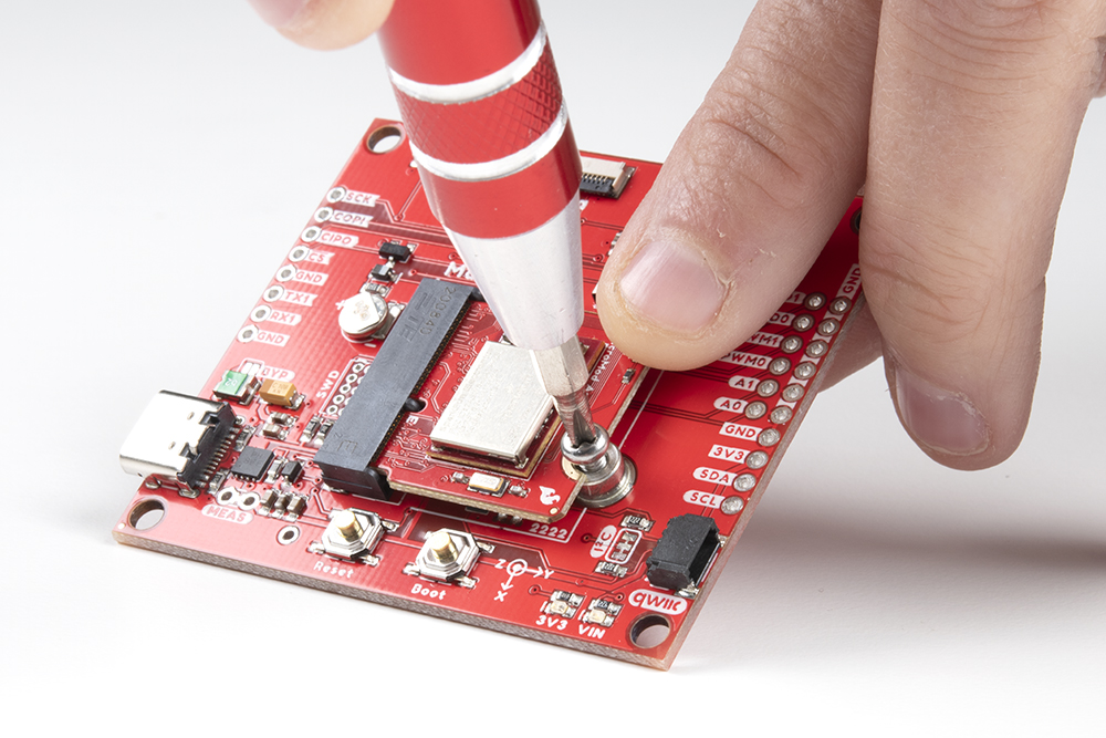
Once the board is in the socket, gently push the MicroMod Processor Board down and tighten the screw with a Phillip's head.
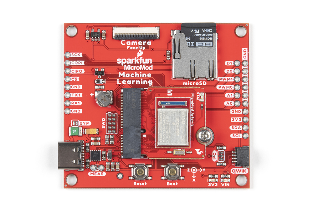
Once the board is secure, your assembled MicroMod system should look similar to the image below!
With your processor inserted and secured it's time to connect your carrier board to your computer using the USB-C connector on the Carrier. Depending on which carrier you choose and which drivers you already have installed, you may need to install drivers.
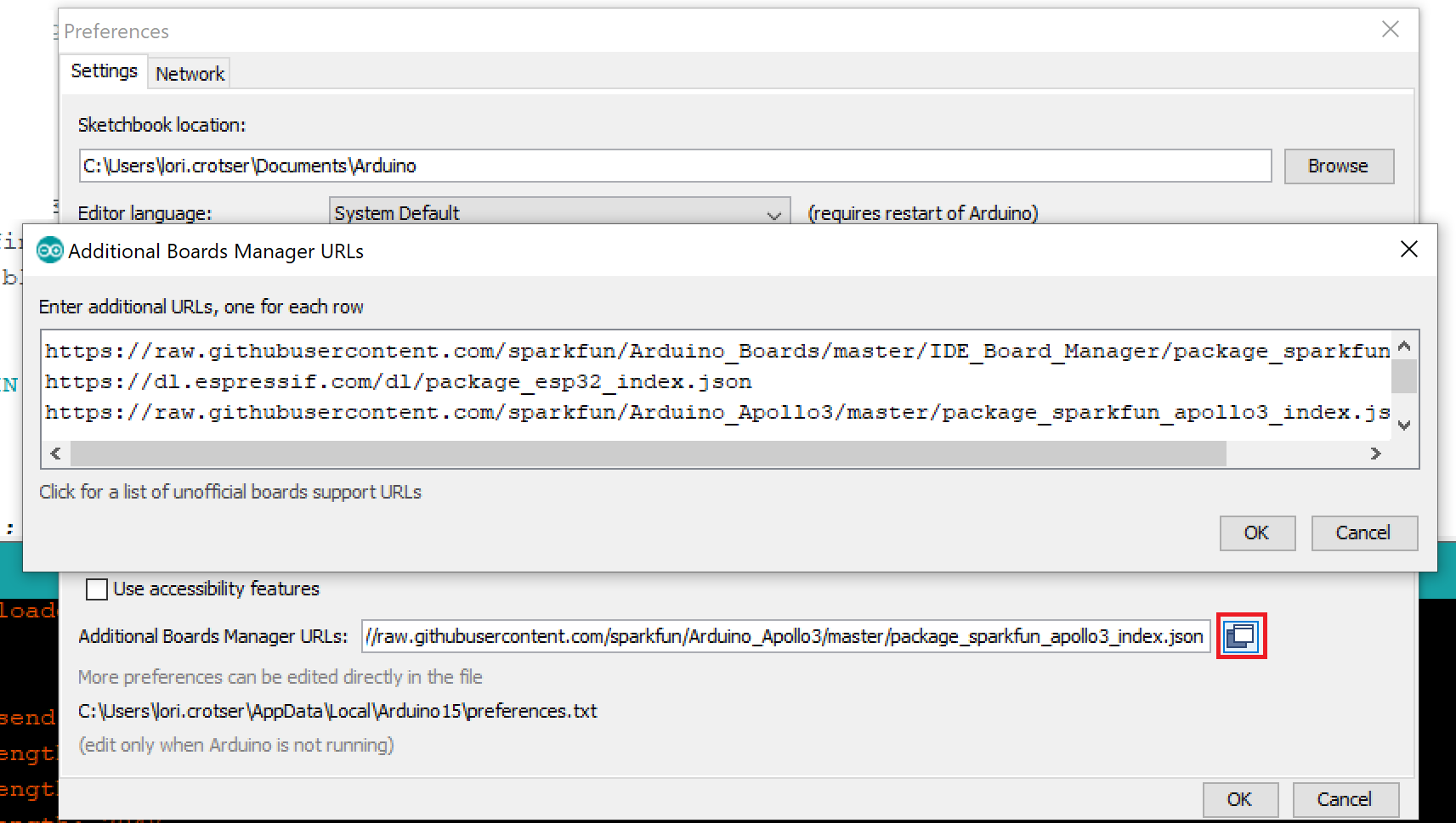
To get started with the Artemis MicroMod Processor Board, you'll need to install the SparkFun Apollo3 Arduino Core. Open the Arduino IDE (must be v1.8.13 or later) and navigate to File->Preferences, like so:

In the "Additional Board Manager URL" box, make sure you have the following json file:
language:c
https://raw.githubusercontent.com/sparkfun/Arduino_Apollo3/main/package_sparkfun_apollo3_index.json
If you have more than one json file, you can click on the button outlined in red and add the json link at the end. It'll look something like the following:

Search for "Apollo3", and you should find the SparkFun Apollo3 Boards board package. Make sure the Version 1.2.1 is selected and click Install.

Installation may take a few minutes -- included in the install are all necessary source files for the Arduino core and Apollo3 libraries, plus all of the compiler and software-upload tools you'll need to use the Artemis with Arduino.
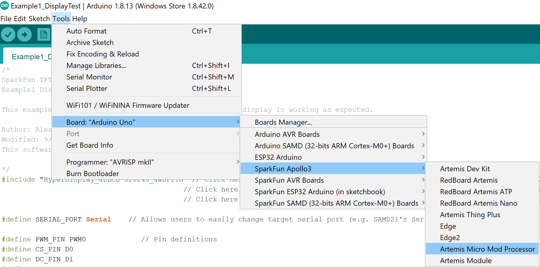
Once the board definitions have been installed, you should see the Artemis MicroMod Processor board under your Tools -> Board -> SparkFun Apollo3 menu.
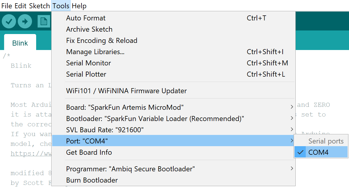
To get started uploading code and working with your Machine Learning Carrier Board, make sure you have the Artemis MicroMod board definition selected under your Tools > Board menu (or whatever processor you've chosen to use).

Then select your serial port under the Tools > Port menu.
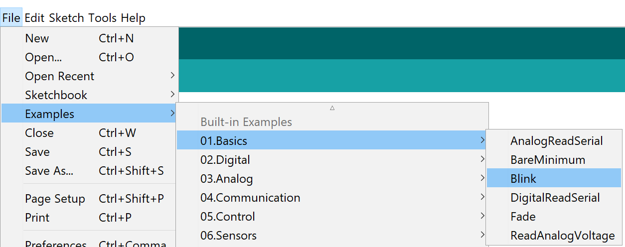
Let's start with something basic - let's blink an LED. Go to File->Examples->01.Basics->Blink.
With everything setup correctly, upload the code! Once the code finishes transferring, you should see the STAT LED on the Artemis Processor Board begin to blink!
Look at all the blinks!
We've built the Arduino core for Artemis from the ground up and a large number of our built-in examples will work out of the box with the Artemis MicroMod Processor Board. You'll find them under File->Examples->'Examples for SparkFun Artemis MicroMod'.
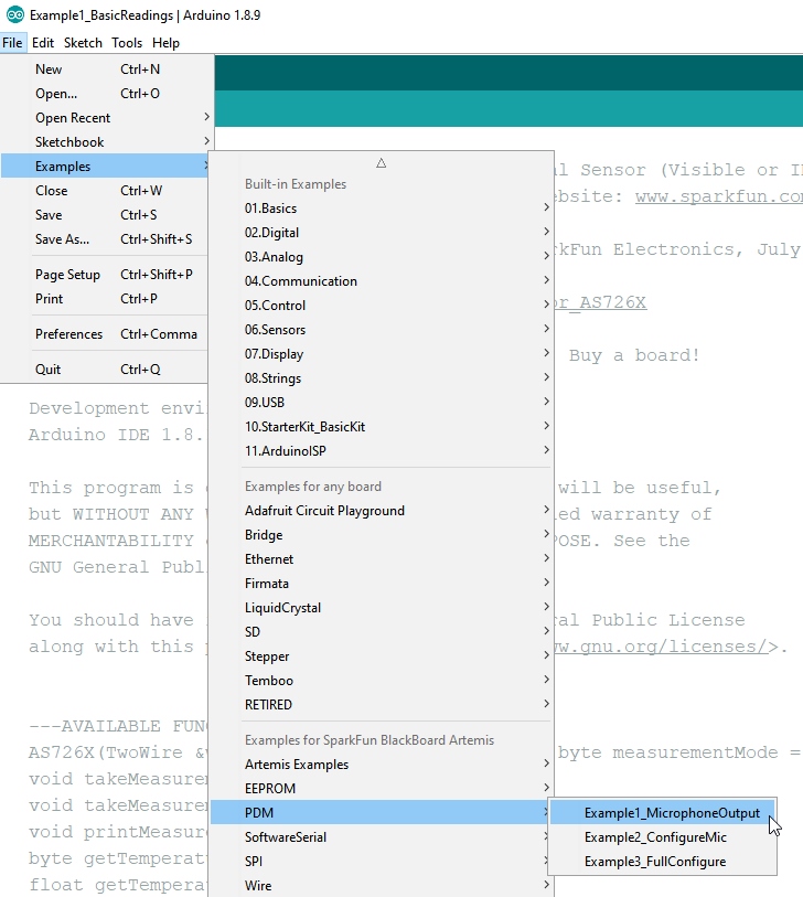
Let's run a quick one from the examples here and take advantage of the two built in microphones on the Machine Learning Carrier Board we're using. Go to File->Examples->PDM->Example1_MicrophoneOutput
Make sure you have the correct board and port selected, and then upload the code. Once the code finishes transferring, open the serial monitor and set the baud rate to 115200. You should see something like the following:
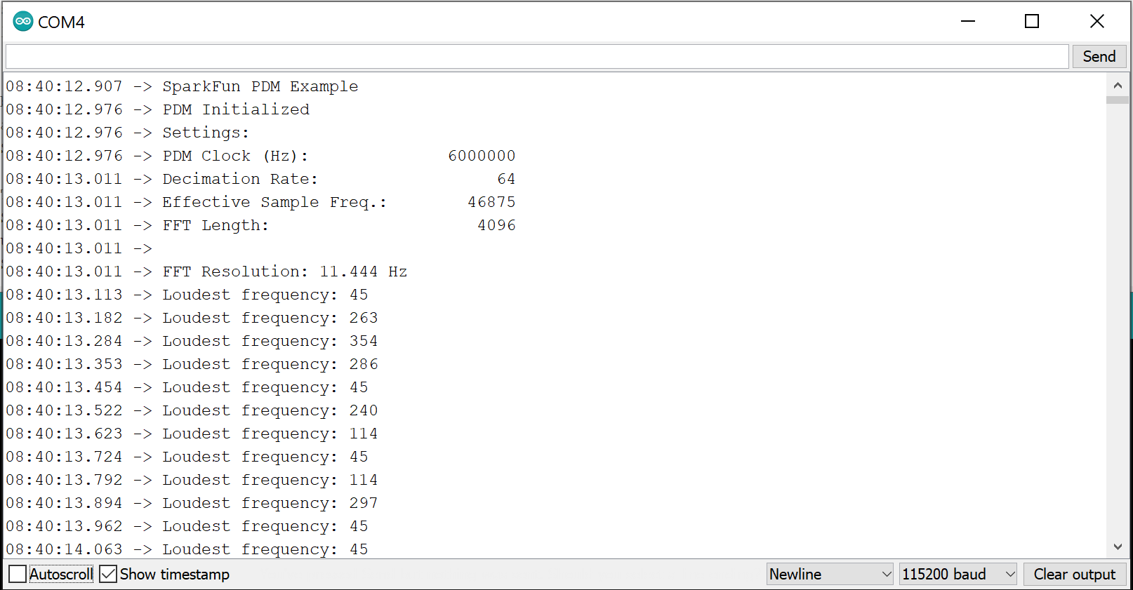
Notice that if you hoot and holler, the output changes.
Within the 'Examples for SparkFun Artemis Micromod' menu, we've got examples for setting up multiple I2C ports (it's amazingly easy), writing to EEPROM, using SoftwareSerial (all 48 pins can be serial!), using the the onboard microphone, and using servos (up to 32!). We're adding more all the time so be sure to keep your core up to date.
With the MicroMod system, the possibilities for examples with all the processor/carrier board are endless, and we just can't cover them all. You'll notice that in this tutorial, we've selected the Machine Learning Carrier Board, but have focused our examples on the Artemis Processor Board. If you're interested in examples specifically for our carrier board, head on over to our Machine Learning Carrier Board Hookup Guide.
Want more information on the Artemis MicroMod Processor Board? Check out these links!
MicroMod Documentation:
Artemis Documentation:
Looking for some project inspiration using your Artemis Processor Board? The tutorials below can help you get started!
learn.sparkfun.com | CC BY-SA 3.0 | SparkFun Electronics | Niwot, Colorado