MicroMod All The Pins (ATP) Carrier Board
 bboyho,
  Elias The Sparkiest
Hardware Hookup
If you have not already, make sure to check out the Getting Started with MicroMod: Hardware Hookup for information on inserting your Processor Board to your Carrier Board.
Getting Started with MicroMod
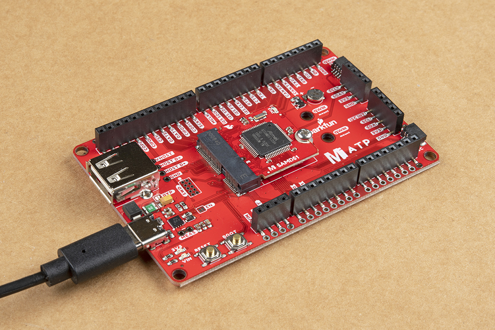
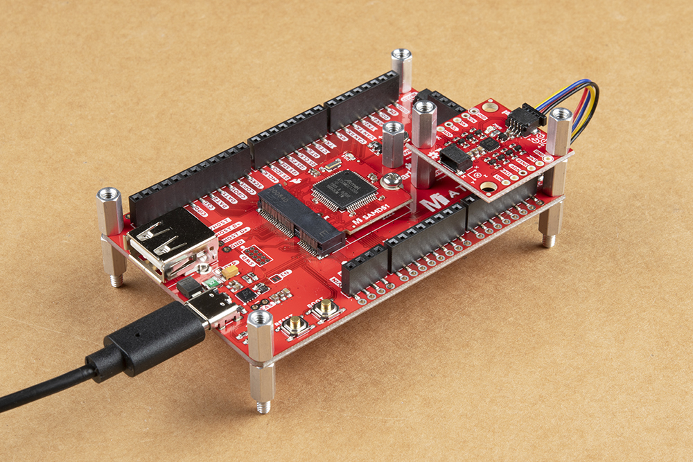
At a minimum, your setup should look like the image below. In this case, we had the MicroMod SAMD51 Processor Board secured in the M.2 connector. To program and power the microcontroller, we inserted the USB-C cable.
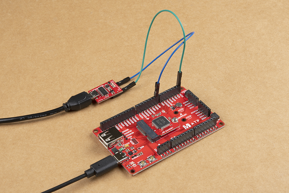
Depending on your setup you may need hardware (jumper wire, cables, header pins, breadboard, etc.) to connect to the board. In this case, we used jumper wire to connect to another board.
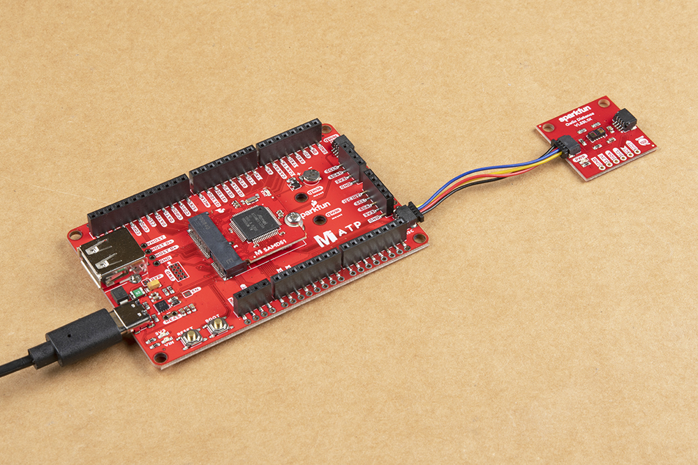
To Qwiic-ly connect I2C devices, simply insert a Qwiic cable between the MicroMod ATP's Qwiic port and your Qwiic device.
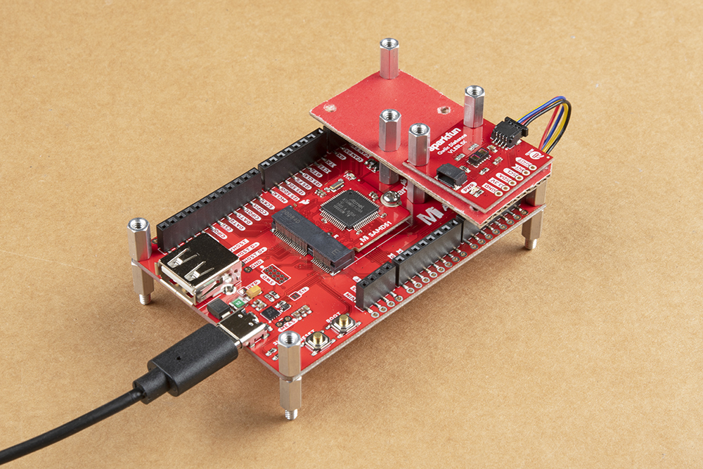
To secure the boards together, you could add standoffs and screws to mount a Qwiic-enabled device that have the standard 1.0"x1.0" sized board. Keep in mind that this will block a few of the header pins below so make sure to plan accordingly.
Depending on the location of the mounting holes, you may need to make an adapter to hold the Qwiic-enabled device securely. Below is an example with mounting holes on the same side instead of diagonal. A piece of cardboard was cut out as shown in the image below. Depending on your personal preference, you could also laser cut, CNC, or 3D printer to make a more sturdy panel for those that need a stronger material.