MCP4725 Digital to Analog Converter Hookup Guide
 Joel_E_B
Hooking it Up
To use the MCP4725, all you'll need is some male headers, a SparkFun RedBoard or other microcontroller, and a means to see your signal. Using an oscilloscope will be the easiest way to get started.
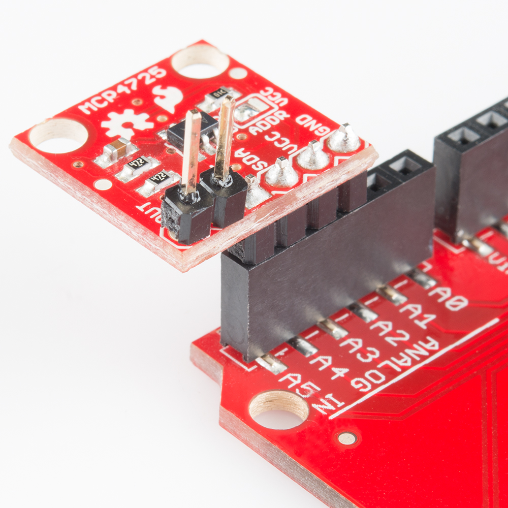
First, solder the headers onto your breakout. We recommend using a 4-pin header facing downward for the power and communication connections and using a 2-pin header facing up for the Out and GND pins. See the below image for an example.

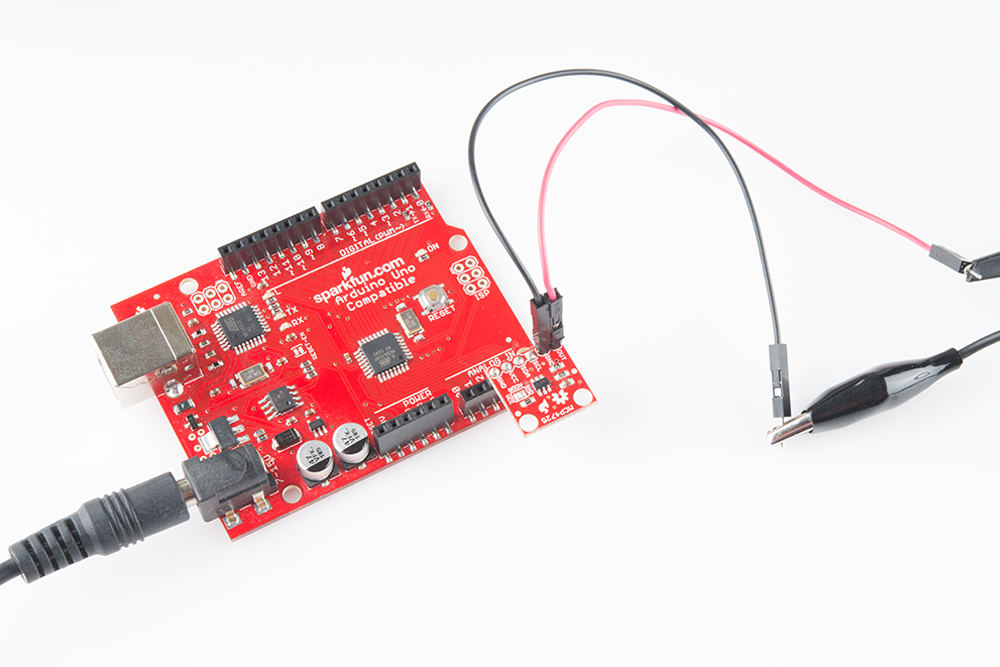
Most Arduino boards have the I2C on the A4 and A5 pins. Then, in the firmware we'll uplaod in the next section, we can set pins A2 and A3 as GND and Vcc respectively to power the breakout. If you prefer to wire everything to a breadboard, you can solder a 6-pin header and connect everything with some jumper wires.
Last, it's time to connect the MCP4725 to whatever device you'll be sending analog signals. In this tutorial, we'll be visualizing the signal with an oscilloscope. Using the o-scope probes, you could connect to the headers directly, or you could use some jumper wires. Make sure to not mix up the Out and GND pins.