MCP4725 Digital to Analog Converter Hookup Guide
 Joel_E_B
Board Overview
Before we discuss hooking up the breakout, let's go over some of the features of this board.
Pinout
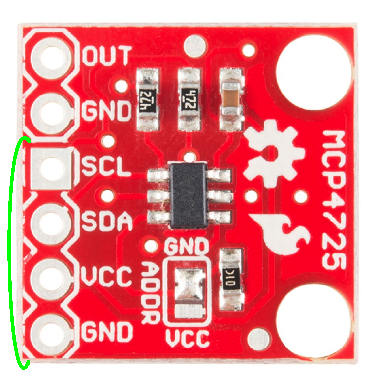
The first thing to point out is the pinout on this breakout now conforms to the standard I2C pinout we've started using on most devices that use the two-wire interface. Thus, it is easy to solder some headers on the breakout and plug it directly into an Arduino with the same pinout for the I2C pins. There is also the signal out and a GND pin grouped together to connect to an oscilloscope or whatever other device you're hooking up to the breakout.
Power
The breakout can be powered anywhere between 2.7V to 5.5V, making it great for both 5V and 3.3V microcontrollers.
I2C Communication
A few features have been added to this breakout to give the user more flexibility with the IC, particularly when it comes to adding multiple DACs to one bus. First, we've broken out the address selection pin (A0) to a jumper pad. By default, this pin is pulled LOW to GND. To change the address of your other device, simply de-solder the jumper and add a blob of solder to the middle pad and the Vcc pad.

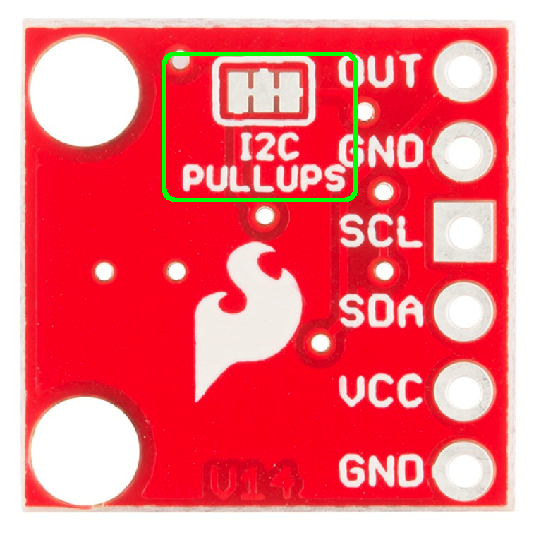
If you're going to have more than one MCP4725 on a bus, you'll also want to disable the pull-up resistors on all but one breakout. To make this easier, we've added another jumper on the back of the board. The pull-ups are enabled by default. If you need to disable them, you'll need to cut the traces on the jumper pad with an Xacto knife. If you ever need to re-enable the pull-ups, simply solder the three pads back together.
Last, there are two mounting holes to mount this board inside the enclosure of your choice.