Making Custom Footprints in EAGLE
 Joel_E_B,
  TheoS
TheoS 
Importing the Bitmap Image into Eagle
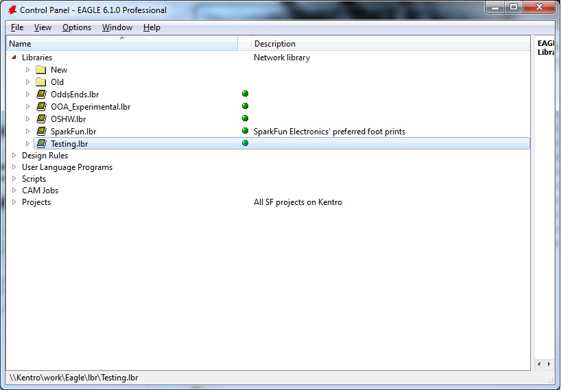
Go ahead and open Eagle, and navigate to whichever library your part lives in. As stated in the title, this tutorial is not for building a footprint from scratch (although you can quite easily), rather it is for customizing an existing footprint to be exactly the right size and shape.
Once open, select your package using the little IC icon in your menu bar.
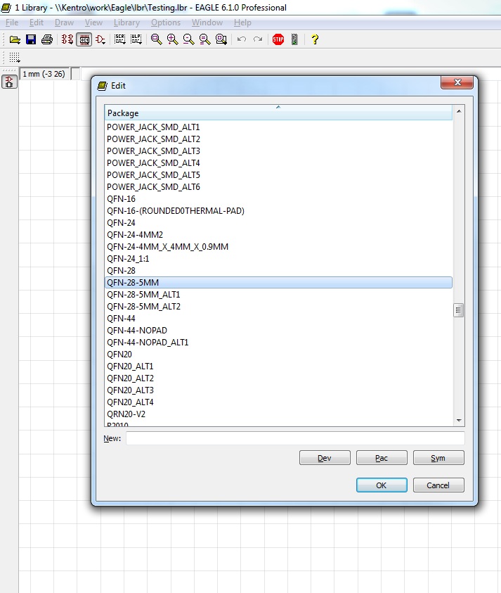
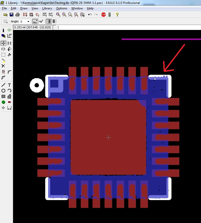
It will open something like this.
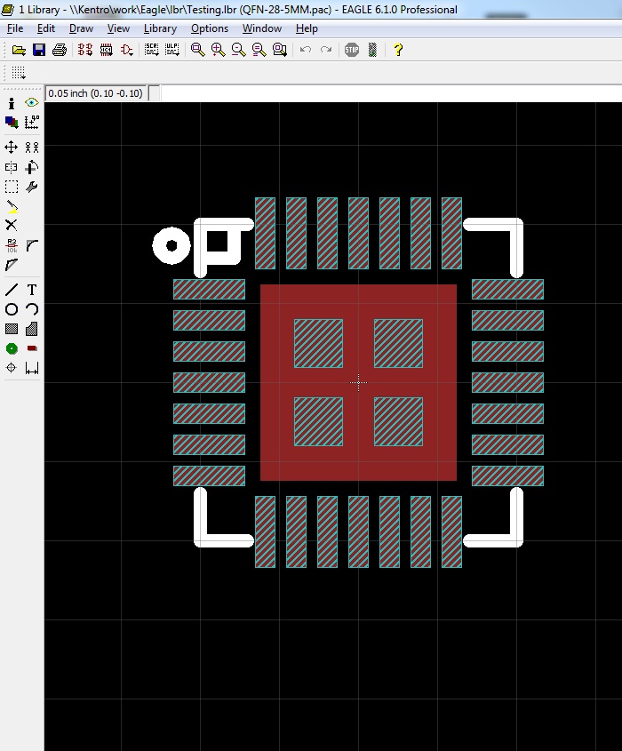
There are a couple of layers available here: red is the copper layer that represents the metal that will be exposed on your board, white stripes represents the stencil layer where solder paste will go if you decide to use reflow ovens as your soldering method (we use this method for all of our SMD components), and plain white represents the top silk layer that will print on your board.
We want to focus on the copper layer: the large center pad and the smaller foot-pads around it.
Before you do anything, it's a good idea to create a new package, copying the existing footprint from the one you just opened. Use the Group-Select tool (alt + F7) to highlight everything, and use the Copy tool to copy everything.
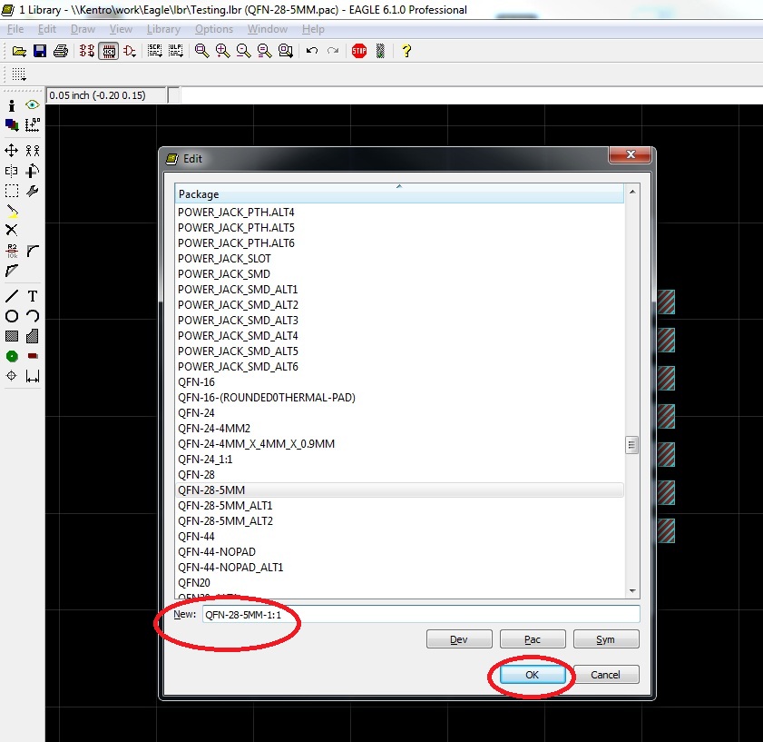
Open the Package list again, and, in the “New” bar, type the new name of your package. I always use the old name and then add “1:1” so that I know this is the one-to-one measured footprint.
Once you have created this new package, use the Paste tool to place everything from the old package.
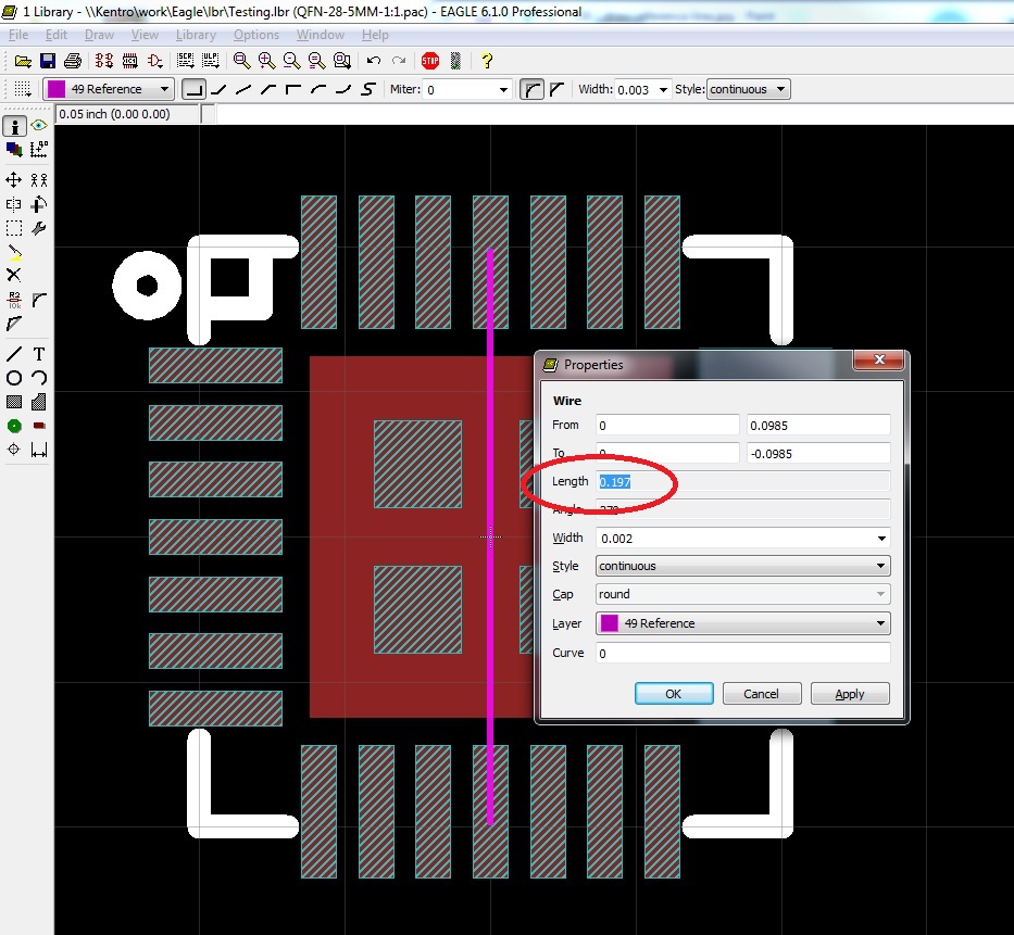
Next, measure your part with a pair of digital calipers. Pick the spot of the piece you measured in your Eagle package, and draw a line of precisely that length.
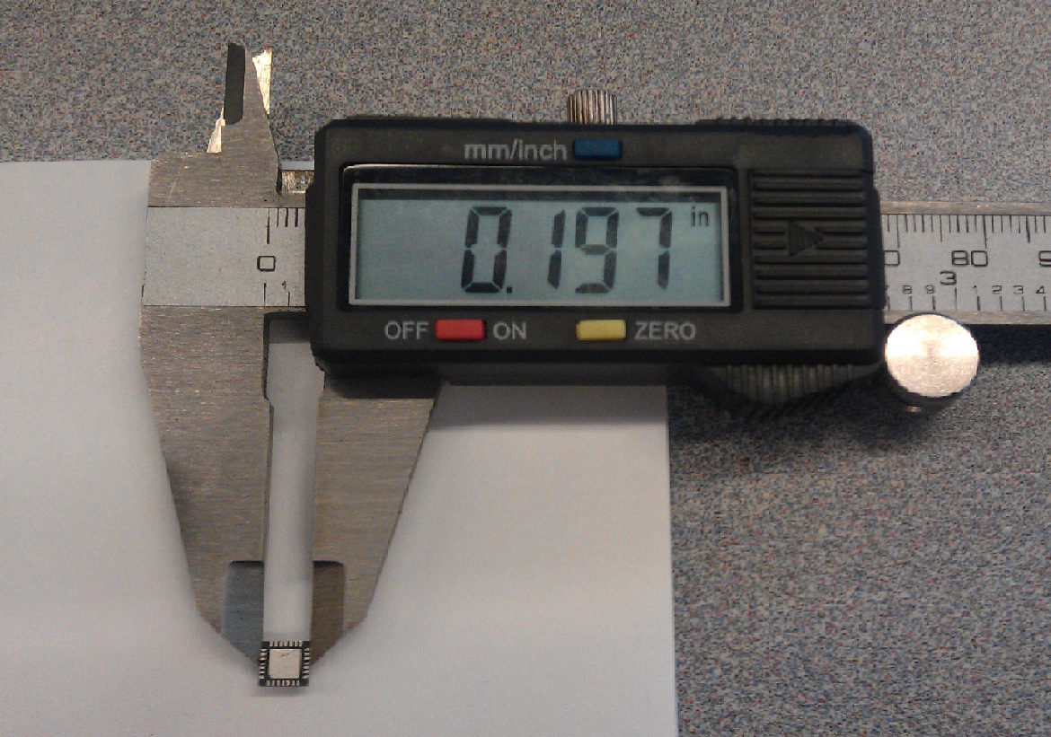
This is for reference purposes (I used the Reference Layer -- purple) so that we can scale our imported .bmp image.
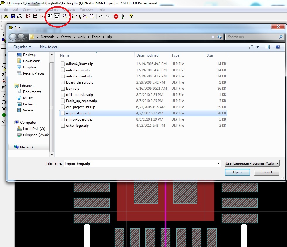
When you have your reference line laid out, click on the ULP button on your toolbar, and select “import-bmp”.This let's you set up parameters and run a script to plot pixels in Eagle based on a Bitmap image.
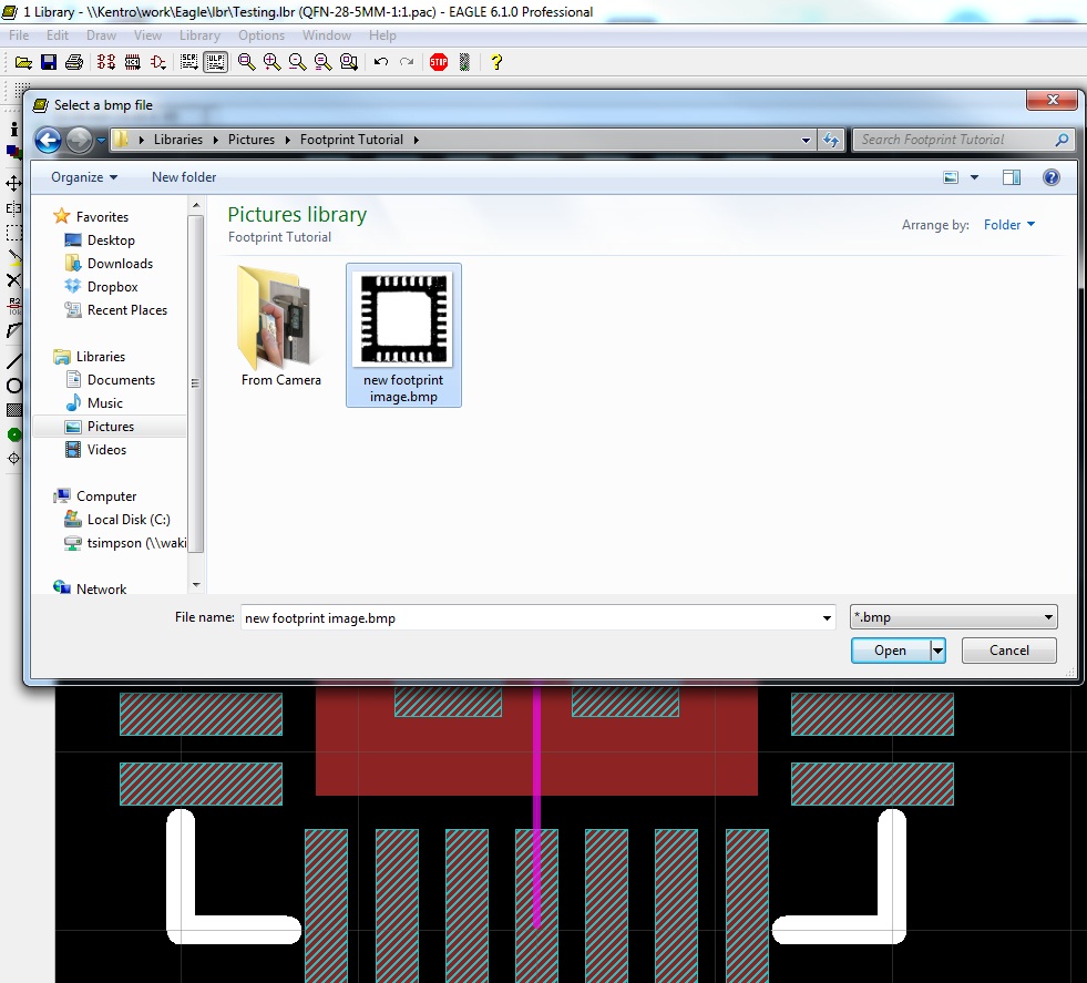
Select your Bitmap image, and then select the colors you wish to include.
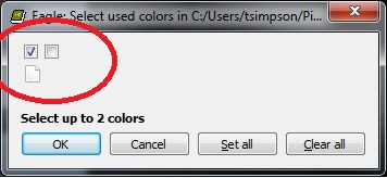
I always select only the first box, so that I only have one layer to work with on the imported image.
Next, you have to select your scale.
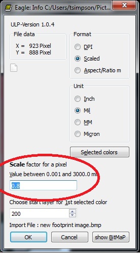
This is where the reference line comes into play. I always have to estimate the scale, run the script, and then measure the image against the reference line. If the image is too small, I select it all (alt + F7), delete it (F3), and re-import the image using a larger scale to run the script. If the image is too large, I use a smaller scale.
Sometimes it takes 5 or 6 importations to get the size exactly right, but it is worth it. Once you have the image in place, the rest is just fitting the copper layer to the pads in the image.
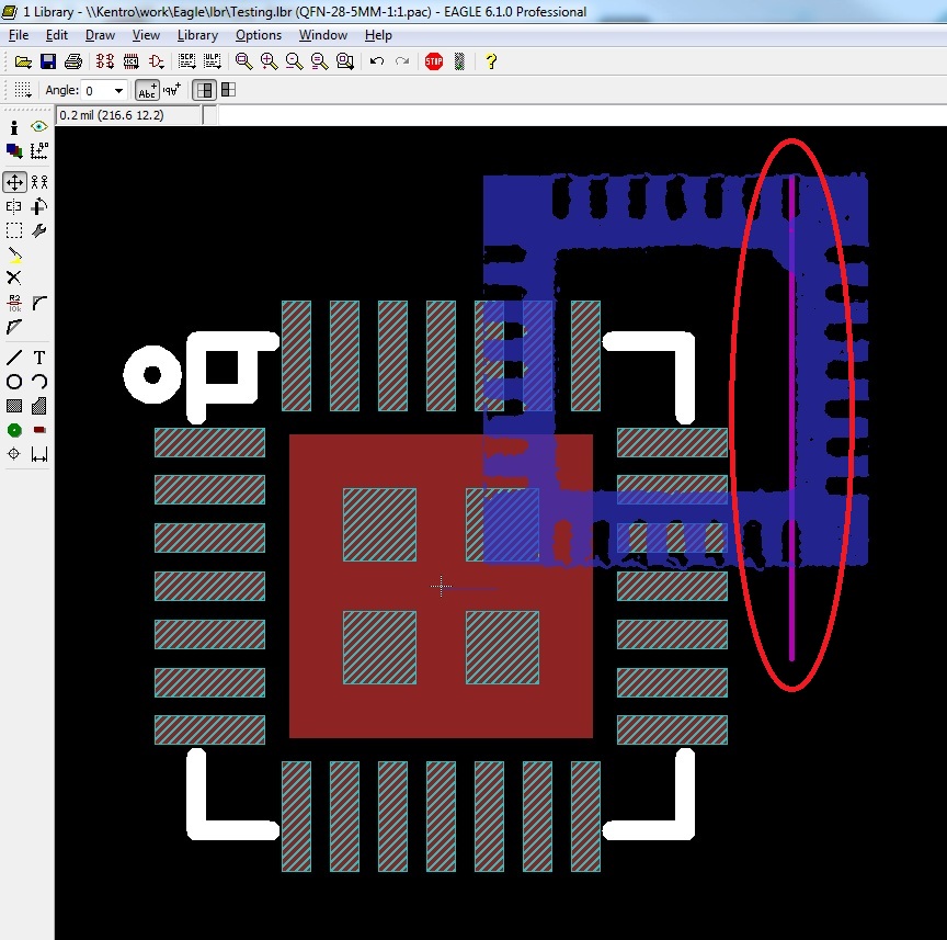
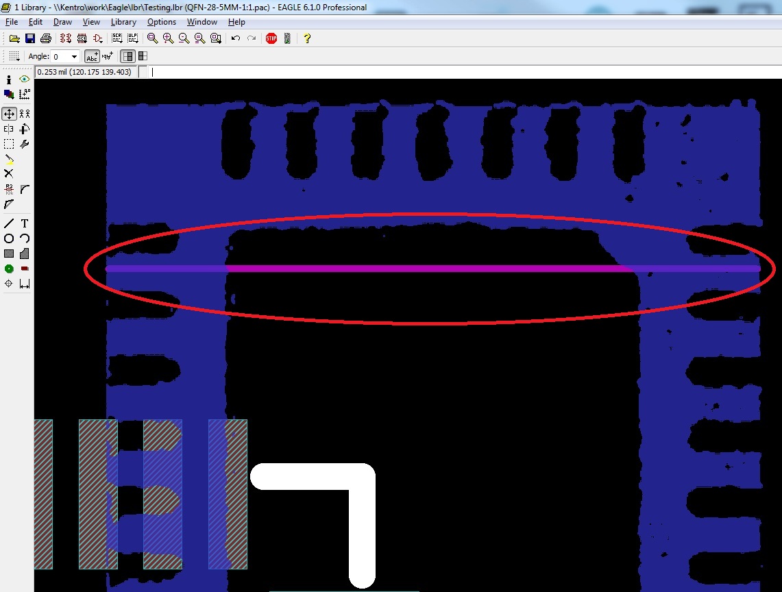
As you can see, the reference line matches the outside edges of the IC image. Also note that the color of the imported image is the color of the Eagle layer on which it was imported (200 is the default) and that by selecting only the first box of colors we get the component as positive space (blue) and the pads as negative space.
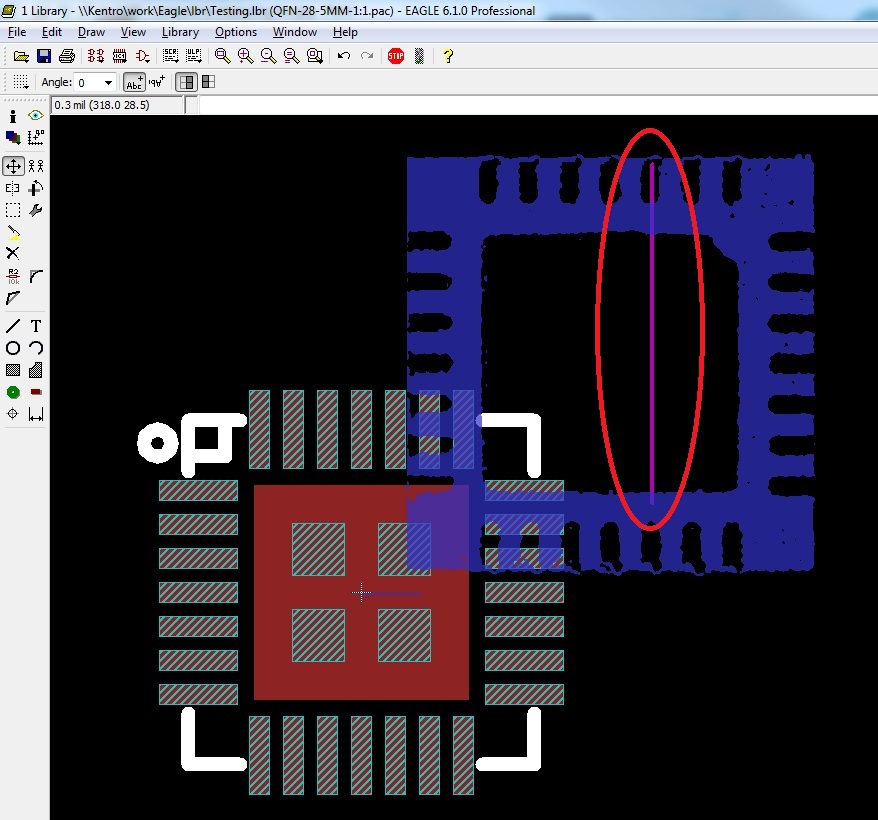
Moving the imported image over the center of the footprint might seem a bit tricky. First, note that the image is broken up into individual pixels that are each their own object. This means you cannot simply select one and move the whole image. It means you have to isolate the layer 200, select the whole image (alt + F7), and then move it over the rest of the footprint (F7). I used the large center pad as my reference point, making sure it is lined up with the center negative space on my imported image.
With that, you should now have an image of the correct footprint sizes and dimensions. Now let's see how to edit our part to match this 1:1 image.