LTC4150 Coulomb Counter Hookup Guide
 MikeGrusin
 Count your Coulombs
If you've worked with circuits a bit, you probably know that you can measure the current a circuit is using by using an ammeter (or more likely a multimeter on the amps setting), and that this is useful information to know.
Instantaneous current consumption is definitely useful, but sometimes you'd like to keep track of cumulative current use, especially when you're trying to determine how much power is left in a battery. Battery life is easy to predict for a circuit that uses a constant amount of current, but things get a lot harder when the circuit is doing different things at different times, like lighting up LEDs.
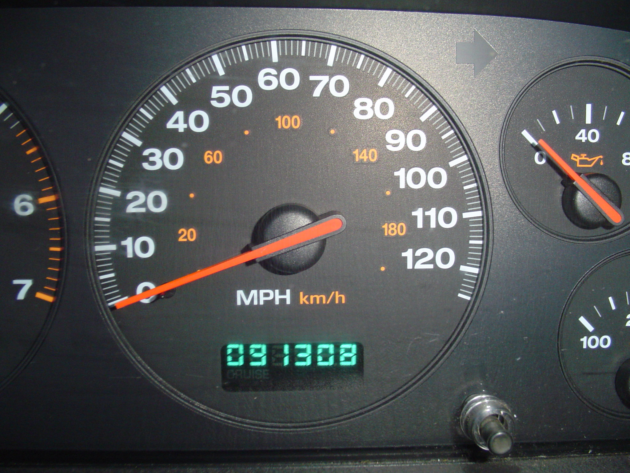
Consider the speedometer and odometer in a car. The speedometer is like an ammeter - it shows you your instantaneous speed, which is good to know, but it can't tell you how far you've gone unless you're constantly keeping track of it. This is the odometer's job; it constantly monitors your speed, accumulates it over time, and tells you how far you've traveled.
A coulomb counter is like an odometer for current. It constantly monitors the current your circuit is using, adds it up, and gives you a pulse each time a given amount of amp-hours have been used. With each pulse, you'll also get a "polarity" signal, which tells you which direction the current is flowing (great for rechargeable batteries!). By counting the pulses and direction, you can maintain an accurate count of how much power your circuit is removing from (or putting back into) your battery. If you start with a full battery, you'll always know exactly how much of it is left! Neat, huh?
Suggested Reading:
Battery Basics
Before we talk about coulombs, let's talk for a minute about batteries.
When you buy a battery from SparkFun (or anywhere else), you'll decide which one you want based on two important numbers:
One of these is how many volts the battery provides. You'll of course want to pick a battery that matches your project's requirements (too much or too little voltage isn't good). Usually we'll recommend a specific battery, such as two 1.5V AA cells for our Simon game.
The other number is the capacity of the battery, or how "big" it is. The higher the capacity, the longer your project will run. Higher capacity batteries are larger and heavier than smaller ones, so you'll need to trade off size and weight vs. runtime -- you might want to use AA batteries for a more portable project, even though they won't last as long as D batteries would.
We measure battery capacity in milliamp-hours (mAh) for small batteries, or amp-hours (Ah) for large ones. This number indicates the theoretical amount of current a battery can provide for one hour before running out of juice.
For example, all of these alkaline batteries have the same voltage (1.5V), but different capacities:
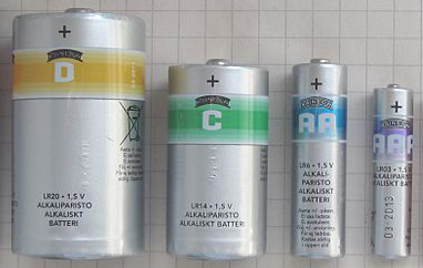
- D: 12000mAh
- C: 8000mAh
- AA: 2700mAh
- AAA: 1200mAh
The AAA battery above has a capacity of 1200mAh, which means it could provide 1.5V at 1200mA (1.2A) for one hour. But that's just the current it could provide for one hour. It could just as easily provide:
- 600mA for two hours (600mA = 1200mAh/2h)
- 300mA for four hours (300mA = 1200mAh/4h)
- 150mA for 8 hours (150mA = 1200mAh/8h), etc.
Conversely, depending on the kind of battery you're using, it might be possible to get:
- 2400mA for half an hour (2400mA = 1200mAh/0.5h)
- 4800mA for 15 minutes (4800mA = 1200mAh/0.25h)
- 72000mA (72A!!!) for 1 minute! (72000mA = 1200mAh/(1/60h))
In reality, the chemicals in a battery can only react at a certain rate, so you can't get unlimited amounts of power even for a short amount of time. However, high-discharge LiPo batteries without protection circuitry CAN discharge breathtaking amounts of power for a few minutes, and are used in model aircraft for exactly this reason.
If you want to know how long a battery will last, the math is easy:
To determine the current a full battery can provide for a given number of hours, divide the total capacity by hours:
1200mAh / 10 hours = 120mA
To determine how long a full battery will last at a given current draw, divide the total capacity by your project's current draw:
1200mAh / 50mA = 24 hours
What is a Coulomb?

A coulomb (like most units named after people, the name is written out in lowercase unless you're specifically referring to that person), is defined as one amp for one second:
1A x 1s = 1C
Because there are 3600 seconds in an hour, one amp hour equals 3600 coulombs:
1Ah = 3600C
How does the LTC4150 Measure Coulombs?
The LTC4150 has an output pin called interrupt, or INT for short (the line above the name indicates that this is an "active low" signal). This line is normally high, but will pulse low each time 0.614 coulombs passes through the device (which also happens to equal 0.1707 milliamp-hours or 0.0001707 amp-hours):
1 INT = 0.614439C
1 INT = 0.1707mAh
1 INT = 0.0001707Ah
Or to look at it another way, you will get 5859 INT "ticks" for each amp-hour:
5859 INTs = 1Ah
Keeping Track of the Charge in a Battery
As you know, battery capacity is measured in mAh (milliamp-hours) or Ah (amp-hours). If your battery holds 1 amp-hour when it's full, you can continuously draw one amp from it for one hour before it's empty. You could also pull 1/2 amp for two hours, or 2 amps for 1/2 hour, etc.
Because it measures amp-hours as you're using them, the coulomb counter makes it very easy to keep track of your battery's state-of-charge (how full it is):
First, assuming you're starting with a full battery, set a variable to your battery's initial state-of-charge (e.g. 1000.0 mAh).
Listen for the "tick" (low) signals from the INT pin.
Each time you detect a tick, check the direction signal, and add or subtract the above per-tick mAh value (0.1707 mAh) to your battery-state variable.
Profit!
As we saw in the last section, one "tick" from the device is equal to 0.0001707 amp-hours. Conversely, it takes 5859 ticks to equal one amp-hour. If your battery has a capacity of two amp hours, then it would take 11718 ticks (5859 * 2) to completely drain (or fill*) the battery.
* Note that in real life it takes a bit more current to charge a battery than you'll later get out of it. This is because the chemical processes that store charge aren't 100% efficient, with the excess turning into heat. The amount of loss varies depending on the type of battery, charge rate, age of the battery, temperature, etc. You can account for this by providing a manual "reset" input when the battery is fully charged, or doing some calibration to see how many more ticks you get when charging vs. discharging (though this will change with battery age, temperature, etc.).
We've written example code that shows you how to do all this, see the Example Code section for more information.
Bonus: Determining Average Current
An additional (and entirely optional) trick is that if you keep track of the time delay between "ticks", you can back out the average current used over that period. The equation is very simple:
mA = 614.4 / (delay between "ticks" in seconds)
Note that because this number is the average current use over the time period, the instantaneous current could be higher or lower. This is also covered in the example code.
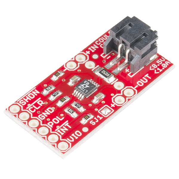
Connecting the Hardware
The LTC4150 Coulomb Counter IC has a very simple interface. It has an INT (interrupt) output that is normally high, but will go low when a given amount of current has passed through the device. There is also a POL output that tells you which direction current is flowing.
Max Ratings
The Coulomb Counter can accommodate power sources up to 8.5V, and currents up to 1A. It works particularly well for single-cell (3.7V) Lipo batteries.
On the interface side, the Coulomb Counter can be attached to systems running at either 3.3V or 5V (see solder jumpers below). The resistors on the board have been selected for those two voltages; other I/O voltages may need different resistor values.
Solder jumpers
There are three solder jumpers on the Coulomb Counter board that configure it for different situations. Please read this section carefully and make any necessary changes before using your Coulomb Counter.
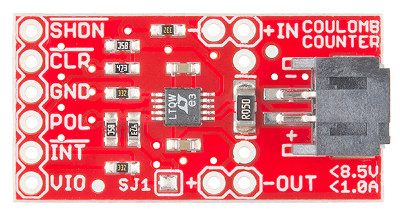
- Solder jumper SJ1 (on the component side of the board) controls the behavior of the INT output. If SJ1 is closed (the default), INT will pulse low and immediately return high. If SJ1 is open (clear), INT will stay low until you use the CLR input to manually reset it. If your code uses interrupts to detect INT ticks, you will probably want to leave SJ1 closed. This will save you the step of having to manually reset INT on each tick. If you are manually polling the INT output, you will probably want to open (clear) SJ1 to give you more time to detect the low signal. See the Example Code section for more information on interrupts vs. polling.
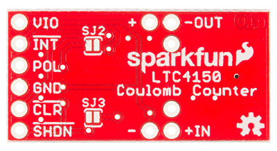
- Solder jumpers SJ2 and SJ3 (on the bottom of the board) select whether you'll be connecting the Coulomb Counter to a 3.3V or a 5V system. If you're using a 5V system (the default), leave these two solder jumpers open (clear). If you will be connecting the Coulomb Counter to a 3.3V system, close both of these jumpers.
To close a solder jumper, melt a small blob of solder onto the jumper so that it bridges both pads, shorting them together.
To open or "clear" a solder jumper, use some solder wick and a hot iron to remove the solder blob bridging the two pads. Place the wick over the blob, and heat the blob through the wick. When the solder melts, the wick will absorb it. When you're done, ensure that the two pads are fully separated (no solder bridging them).
Electrical Connections
As you would when using an ammeter, you will need to install your Coulomb Counter between your power source (usually a battery) and your circuit. All the current your circuit uses needs to pass through the Coulomb Counter to be measured.
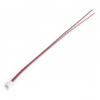
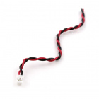
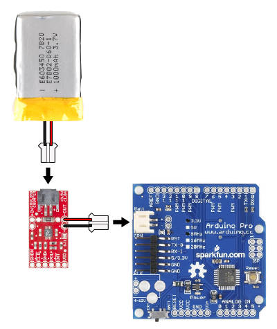
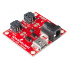
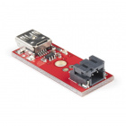
At one end of the breakout board are headers labeled IN and OUT. Connect your battery or power supply to the IN header or JST battery connector (they're identical), and connect the OUT header to your project. The JST connector matches the connectors used on SparkFun Lipo batteries, and can be used to connect a single-cell 3.7V Lipo battery as your power source. (You could also add a 2-pin JST pigtail or adapter to your own battery or other power source and plug it into this connector).
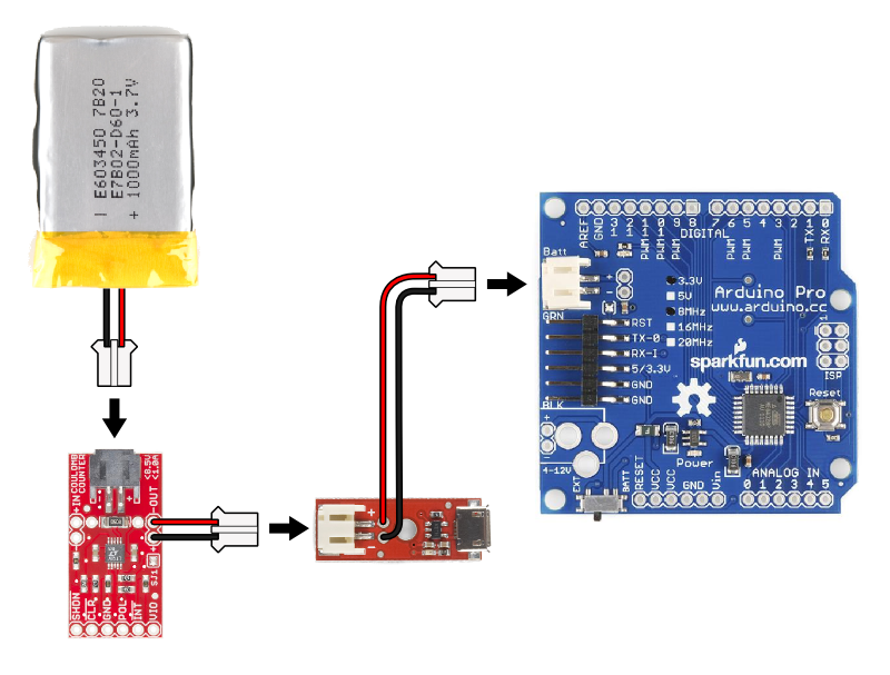
Note that if you'll be using both the Coulomb Counter and a Lipo charger, connect the Coulomb Counter (not the charger) directly to your battery. This way the Coulomb Counter can monitor both charging and discharging:

PROTIP: if you connect a JST pigtail to the output of the Coulomb Counter, you can conveniently plug it straight into your system's JST battery connector:
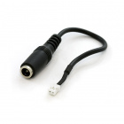
You can even do the same thing to a Lipo charger, for complete plug-and-play modularity:
Interface pins
At the other end of the Coulomb Counter, you'll find a header with six pins. These are the pins you'll need to connect to your microcontroller. Depending on what you want to do, you'll need at least the first four pins:
| Name | Function | Direction | Notes |
| VIO | I/O Voltage | Power | Connect to 3.3V or 5V depending on your system. Note that you may need to change jumper settings (see above). |
INT |
Interrupt | Output (from CC) |
Goes low when 0.0001707 amp-hours have passed through the board. Is cleared (goes high) when CLR goes low. Connect to an interrupt input pin. |
| POL | Polarity | Output (from CC) |
Indicates direction of current flow. Low = current from IN to OUT (discharging). High = current from OUT to IN (charging). |
| GND | Ground | Power | Connect to GND pin on your system. |
| CLR | Clear | Input (to CC) |
If INT is low, make CLR low to reset INT. This is done automatically if SJ1 is closed (ties CLR and INT together). This pin can be left disconnected if SJ1 is closed and you are using interrupts to sample INT. |
| SHDN | Shutdown | Input (to CC) |
If SHDN is low, the chip will be held in reset. There is a pullup resistor from this pin to VIO, so if you leave it disconnected, the board will remain active. This pin can be left disconnected if you do not need the shutdown function. |
<
p>
PROTIP: When you see a signal name that contains an asterisk or has a line over it, that's an indication that this signal uses "negative logic". In negative logic, a low logic level means the signal is asserted or active. Thus, if you see a signal named RESET, you must provide a low signal to reset the part, and keep it high at other times.
Note that the Coulomb Counter is powered by the IN header (usually your battery) and not by the VIO pin, which is used only as a voltage reference for the output pins. This is so that the small amount of power used by the Coulomb Counter itself is included in its measurements for maximum accuracy. The Coulomb Counter uses under 1mA when it's running, and you can use the SHDN (shutdown) input to reduce its power consumption further (though it will not be able to keep track of current use while shut down).
Typical Connections
Before plugging your Coulomb Counter into your microcontroller, see the Solder Jumpers section above for instructions on setting up the board for a 3.3V or a 5V system.
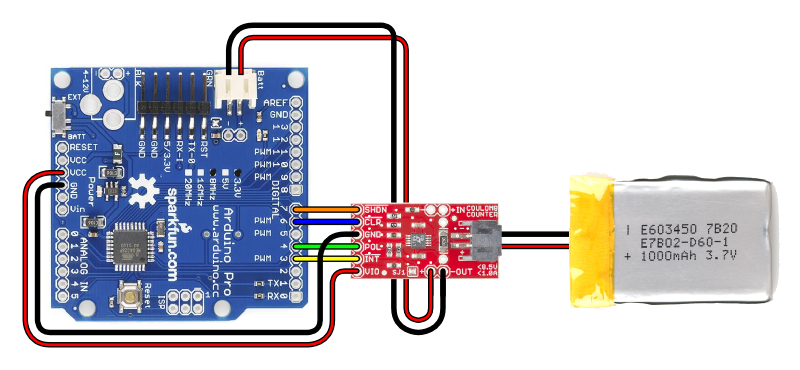
Our Arduino Example Code has been written so that you can plug the Coulumb Counter board directly into Arduino digital pins 2 through 7 as shown below. (We've made D2 permanently HIGH for VIO, and D5 LOW for GND.)
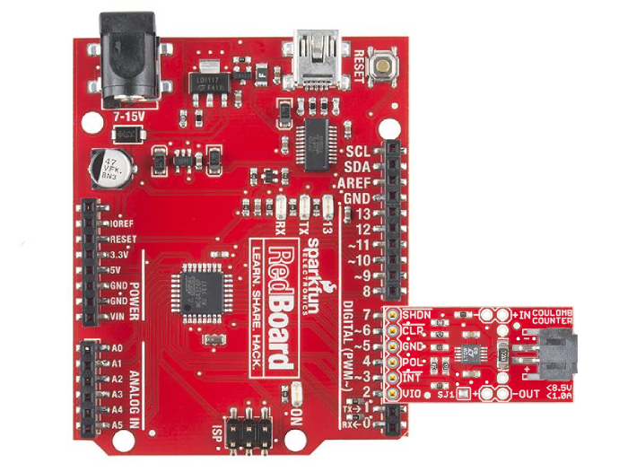
This makes it easy to test out the board, but in most cases you will want to use wires to connect the boards so as not to waste valuable I/O ports on pins that could be left disconnected. Speaking of which:
Do I need to use all six pins?
Probably not!
If you will be using interrupts to sample the INT signal (recommended), you can leave the CLR pin disconnected.
If you do not need shutdown functionality, you can leave the SHDN pin disconnected.
You can connect VIO and GND to your system's regulated voltage (3.3V or 5V) and GND. You don't need to waste I/O pins.
If you're using interrupts to sample the INT signal (recommended), you can get away with only two I/O ports (INT and POL) plus VIO and GND. Note that for ATmega 328-based Arduinos, INT can only be connected to D2 or D3 without additional pin-change-interrupt libraries.
3.3V Systems
The Coulomb Counter is well-suited for 3.3V systems like the Arduino Pro or Pro Mini:
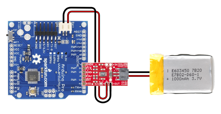
These diagrams show the use of a single-cell Lipo battery powering the system. Note that you should also connect 3.3V to VIO and GND to GND for the logic level reference. You can do this with the Arduino's VCC (3.3V) line, or connect it to an I/O pin set HIGH as we do in our Example Code.
5V Systems
For 5V systems like the Arduino Uno or SparkFun Redboard, you can run an unregulated supply up to 8.5V through the Coulomb Counter to the Arduino's VIN terminal. Note that you will need to connect 5V to VIO for the logic level reference. You can do this with the Arduino's 5V line, or connect it to an I/O pin set HIGH as we do in our Example Code.
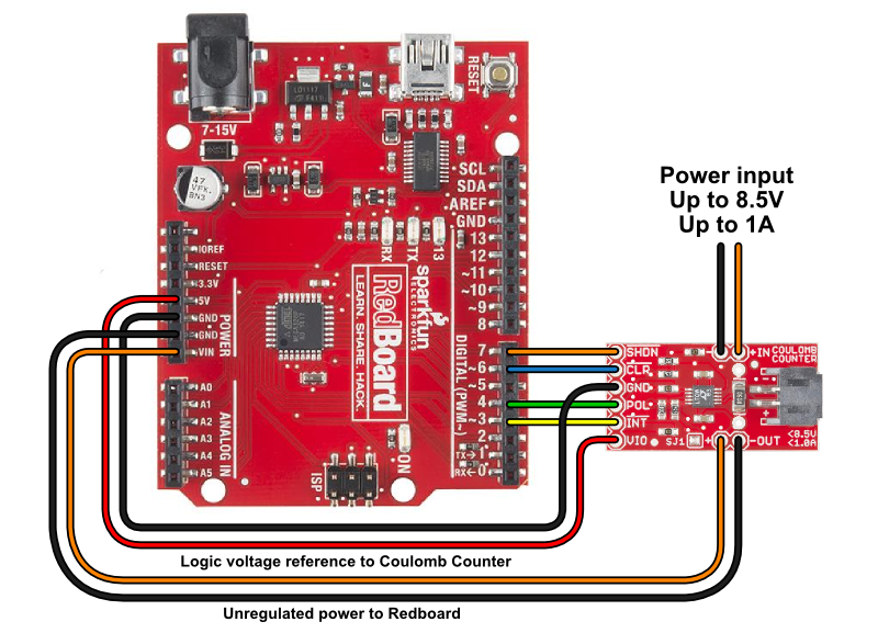
If you want to power the Arduino from a regulated 5V line, you can do that as well. Run the power supply through the Coulomb Counter to the Arduino's 5V terminal. You will also need to get 5V to the Coulomb Counter's VIO pin, and so on.

Running the Example Code
We've included two example programs for the Arduino microcontroller to show you how to use the Coulomb Counter. If you're not using an Arduino, the example code is very straightforward and should be easily adapted to other microcontrollers.
To Interrupt or Not to Interrupt?
The two code examples are called "Coulomb_int" and "Coulomb_polling". They do exactly the same thing (measure battery consumption), but differ in the way they detect changes on the INT output. Which one you choose will depend on your requirements and skill level.
Interrupts
The "standard" way to detect a pin change is to use interrupts. Interrupts are a hardware feature built into microcontrollers that allow them to handle high-priority events immediately.
To use interrupts, you write a special function called an Interrupt Service Routine (ISR) and set up the hardware appropriately. Then whenever a special interrupt pin on your microcontroller receives the desired input (goes high or goes low), whatever is going on in the main loop is paused, and your ISR function runs. When the ISR function finishes, the main loop picks up right where it left off. This all happens automatically - the only way the main loop would know that anything had happened would be if the ISR function changed some variables behind the scenes (such as how much battery is left, which is exactly what we do in the example code).
The interrupt example code has the advantage of not needing the CLR input, so you can get away with only two I/O pins; INT and POL.
Note that on ATmega 368-based Arduinos, only two pins support external interrupts without additional libraries: D2 (INT0) and D3 (INT1). We use D3 in our example code.
Polling
Interrupts are very useful, but if you're still learning the finer points of programming, there's no shame in using a simpler technique called polling. Polling is simply testing an input over and over again until it becomes the state you're looking for.
By default, the Coulomb Counter is set up so that the INT output will go low and immediately return high. It will only be low for a few microseconds (millionths of a second!), which is enough for interrupt-based code to detect the falling edge, but random checking will almost certainly miss such a brief signal.
However, if you open (clear) solder jumper SJ1, each time INT goes low, it will stay low until you manually reset it. This makes it much easier to write polling code, as INT will stay low until the next time you get around to checking it. To reset it, make CLR low and then high.
The polling example code has the disadvantage of requiring three I/O pins as opposed to two (INT, CLR, and POL). You should also be careful to ensure that you check INT faster than every half-second or so; if a new INT comes in while the old one is still low, you will miss it.
Wiring the Hardware
Here are the minimum required connections for the example sketches. (See the previous page for wiring diagrams.)
If you want to try the interrupt example code:
- Leave solder jumper SJ1 closed (the default)
- You will need to connect (at least):
- VIO to VCC
- INT to D3
- POL to D4
- GND to GND
If you want to try the polling example code:
- Open (clear) solder jumper SJ1 (Instructions)
- You will need to connect (at least):
- VIO to VCC
- INT to D3
- POL to D4
- GND to GND
- CLR to D6
For EITHER version of the code:
- Ensure that SJ2 and SJ3 are both open (clear) for a 5V Arduino, or both closed (soldered) for a 3.3V Arduino.
Downloading the code
The example code is maintained at the Coulomb Counter BOB Github repository. You can download a ZIP file of the entire repository (or clone it to your computer if you have the github software installed), or save the sketches directly:
For either version of the code, you should change line 120 to reflect the full capacity of your lipo battery. The default is 2000mAh:
volatile double battery_mAh = 2000.0; // milliamp-hours (mAh)
This will provide an accurate readout of how many mAh remain in your battery as you use it.
Running the Example Code
Upload the code to your Arduino as you normally would. Open a serial monitor window set to 9600 baud. You should see a reset message, followed by updates as INT "ticks" occur.
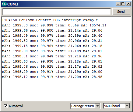
The columns from left to right are:
- mAh (milliamp-hours) remaining in the battery (subtracted from the battery size value at line 120)
- State-of-charge (percentage remaining)
- Time delay between ticks
- Average mA computed from the last time delay.
Note that the first mA reading will be incorrect, as it requires the time delay between two readings to perform its calculations.
Remember that if you don't have anything connected to the output of the Coulomb Counter, the current passing through the board will be zero and you will not see pulses from the INT pin. (You may get one pulse every 10 minutes or so from the very small amount of current that the LTC4150 chip uses.)
Resources and Going Further
Changing the Sense Resistor
The Coulomb Counter uses a sense resistor to measure current. This very small resistor (0.05 ohms) is the only component located between the input and the output. The LTC4150 measures the voltage drop across this resistor; thanks to Ohm's law the voltage drop is directly proportional to the current passing through the resistor.
We've installed an 0.05 ohm sense resistor in the Coulomb Counter, which is why the maximum current is 1A and you get 5859 "ticks" per Ah. If you want more resolution (ticks per Ah) at a lower maximum current, or want more current* at less resolution, you can replace this resistor with a different value part. You will need to remove the existing part and replace it with another surface-mount part, or use the provided footprint for a through-hole resistor. Refer to the LTC4150 datasheet for information on resistor selection. There is also a spreadsheet in the Github documentation folder that may be useful.
* Note that the PCB traces on the board are not designed to handle more than 1.6A continuously, and the JST connectors are not designed for more than 2A.
Also note that there is no easy way to increase the maximum supply voltage of 8.5V. Sorry!
Using the SHDN Input
You can reset or shut down the LTC4150 by making the SHDN input LOW. This will reduce the power consumption of the board, but the LTC4150 will not measure current consumption in this mode. This input has a pullup resistor; if you do not need shutdown functionality, you can leave this input disconnected.
We hope you find the LTC4150 Coulomb Counter useful. Now that you've successfully got your LTC4150 Coulomb Counter up and running, it's time to incorporate it into your own project! For more information, check out the resources below:
- Schematic
- Eagle Files
- Datasheet (LTC4150)
- GitHub (Example Code & Design Files)
- Product Video
Need some inspiration for your next project? Check out these related tutorials!
Battery Technologies
Uh-Oh Battery Level Indicator Hookup Guide
Battery Babysitter Hookup Guide
LilyPad Basics: Powering Your Project
If you have any problems, feel free to contact our Tech Support Department. And let us know what you're using it for!