Load Cell Amplifier HX711 Breakout Hookup Guide
 Sarah Al-Mutlaq,
  Alex the Giant
 Hardware Hookup
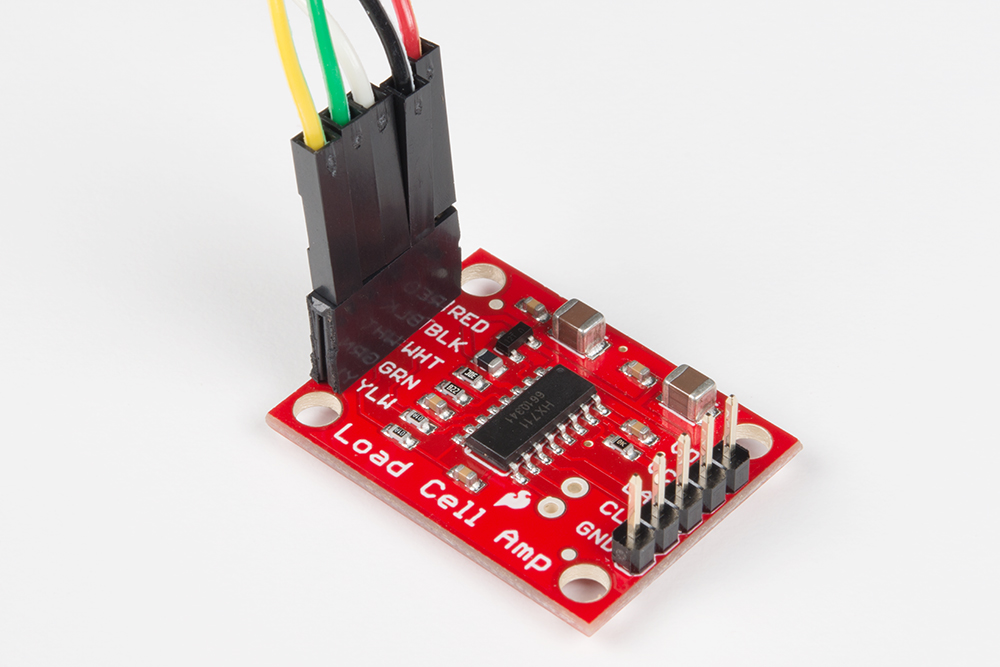
The HX711 Load Cell Amplifier accepts five wires from the load cell. These pins are labeled with colors; RED, BLK, WHT, GRN, and YLW.
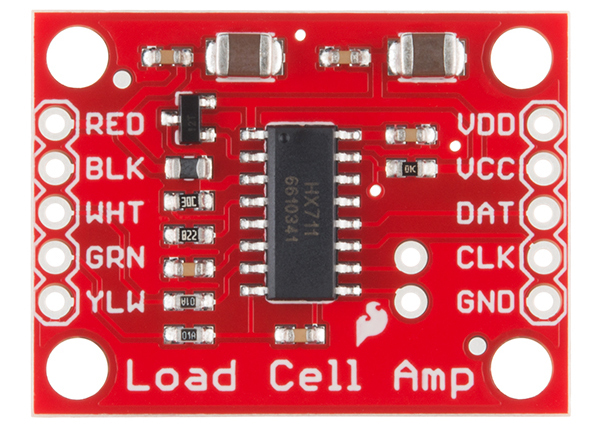
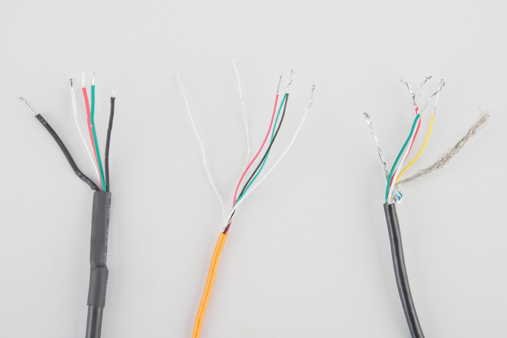
These colors correspond to the conventional color coding of load cells, where red, black, green and white wires come from the strain gauge on the load cell and yellow is an optional ground wire that is not hooked up to the strain gauge but is there to ground any small outside EMI (electromagnetic interference). Sometimes instead of a yellow wire there is a larger black wire, foil, or loose wires to shield the signal wires to lessen EMI.
In general, each load cell has four strain gauges that are hooked up in a wheatstone bridge formation as shown below.
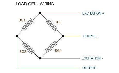
The four wires coming out from the wheatstone bridge on the load cell are "usually":
| Wheatstone Bridge Node | "Typical" Wire Color |
|---|---|
| Excitation+ (E+) or VCC | RED |
| Excitation- (E-) or GND | BLACK or YELLOW |
| Output- (O-), Signal- (S-), or Amplifier- (A-) | WHITE |
| O+, S+, or A+ | GREEN or BLUE |
Some load cells might have slight variations in color coding such as blue instead of green or yellow instead of black or white if there are only four wires (meaning no wire used as an EMI buffer). You might have to infer a little from the colors that you have or check the datasheet on the load cell, but in general you will usually see these colors.
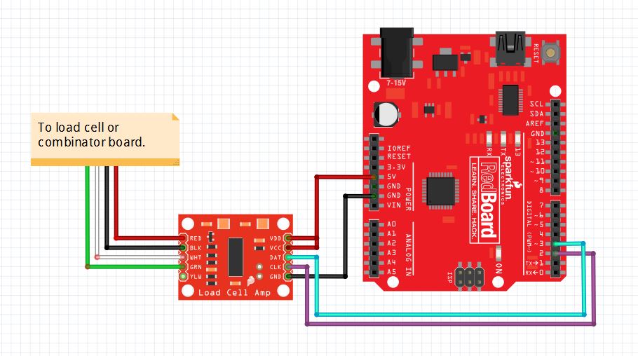
Once the load cell is is hooked up to the amplifier, you can hook up VDD, VCC, DAT, CLK, and GND to a microcontroller such as a RedBoard or Arduino board.
Note: VCC is the analog voltage to power the load cell. VDD is the digital supply voltage used to set the logic level.
The example code has DAT and CLK hooked up to pin 3 and 2 respectively, but this is easily changed in the code. Any GPIO pin will work for either. Then VCC and VDD just need to be hooked up to 2.7-5V and GND to ground on your microcontroller.
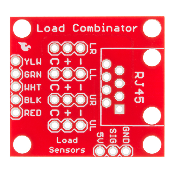
Strain Gauges with the Load Cell Combinator Board
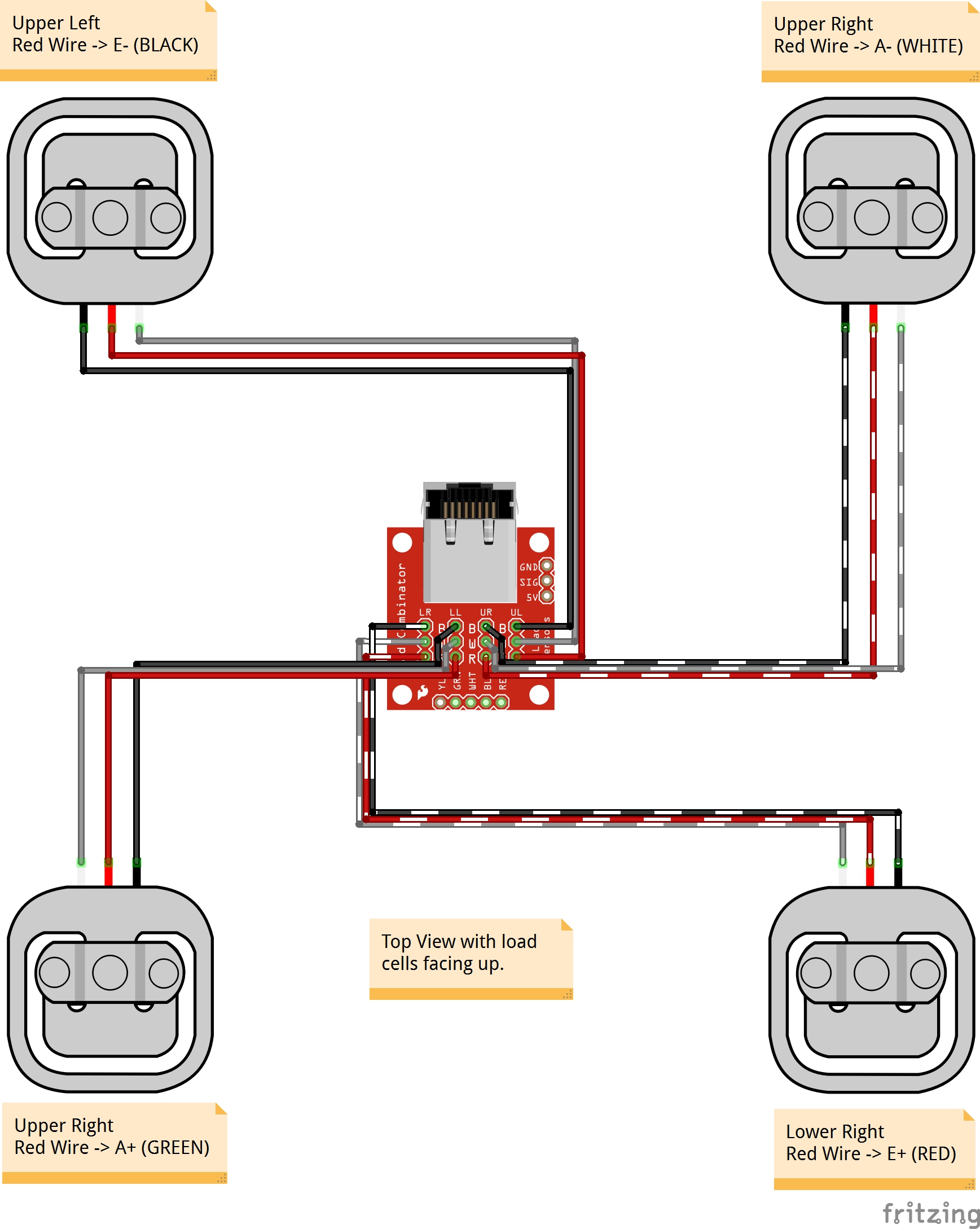
Now, if you would like to set up four single load sensors with our combinator board and amplifier, connect the five pins labeled RED, BLK, WHT, GRN, YLW on the combinator to the matching pins on the amplifier. Next, connect each of the four load sensors to the following pins:
| Single, Strain Gauge (i.e. Load Sensor) "Typical" Wire Color |
Load Combinator Board |
|---|---|
| RED | C |
| WHITE | + |
| BLACK | - |
Another nice thing about our combinator board is that most home scales use four single strain gauge load sensors, so this is a handy board for hacking your own scales at home!
For load sensors, there isn't a set color coded standard. The hacked home scale can have different wire colors. Comparing the scale pictured above with the load sensor schematic, while the black wires matched, the red and white wires were swapped. Also, only two of the four sensors used a white wire for the 'center tap' of the load sensor, the other two used green. I connected the black wires to "-", the red to "+", and the white and green wires to "C".
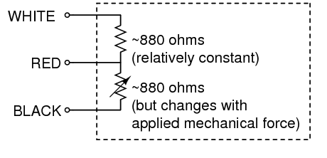
To determine how to hook up your single strain gauge load cells to the combinator, measure the resistance with a multimeter between the three wires. You should find a larger resistance (close to double) between a pair. In our example, the resistance between red and black was 1.6 kΩ (i.e. 1600Ω), and the resistance between white/green and red was 800 Ω. Therefore, the center tap to the strain gauge is the white/green wire. The center tap or center pin of your strain gauge connects to the "C" pin on the combinator. The larger resistance wires (red and black in this example) connect to the "+" and "-" pins on the combinator.
The combinator board hooks up the four load sensors in such a way that two resistors in the wheatstone bridge configuration are constant values and the other two are variable in this way:
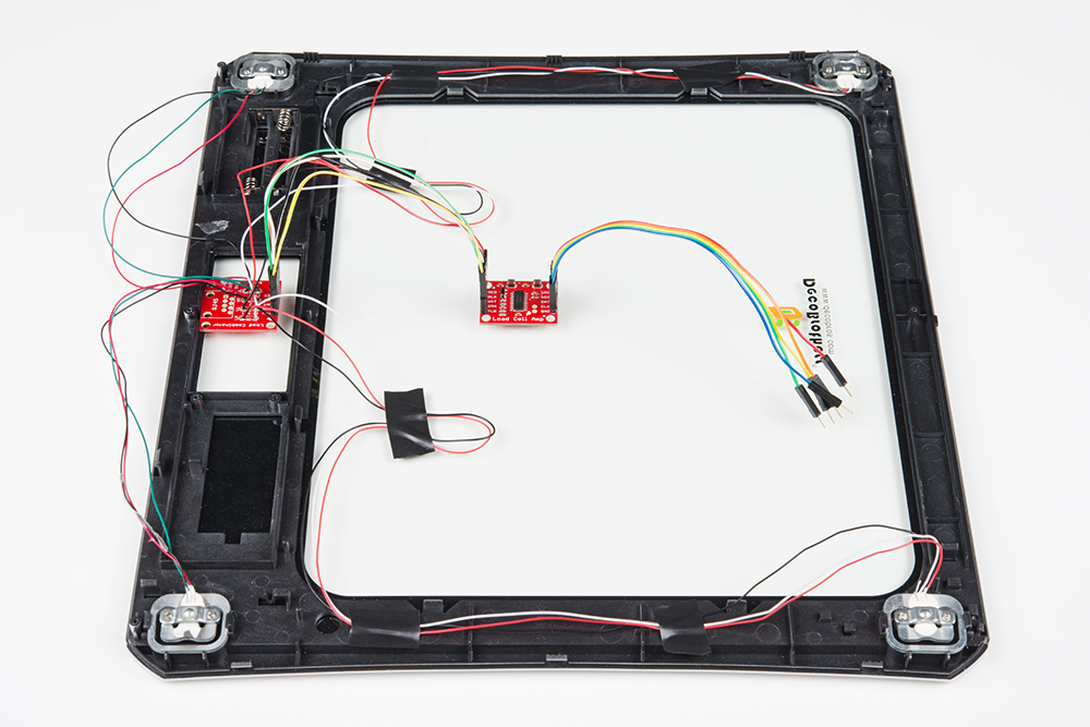
Once you have the combinator board successfully soldered to the twelve wires, you can now connect it to the HX711 amplifier board via the 4 standard load cell wires. Connecting the yellow pin is optional. You can use short jumper wires or if your electronics are a long distance away from your scale consider using an RJ45 connector and an ethernet cable to connect the combinator to the HX711 amplifier.
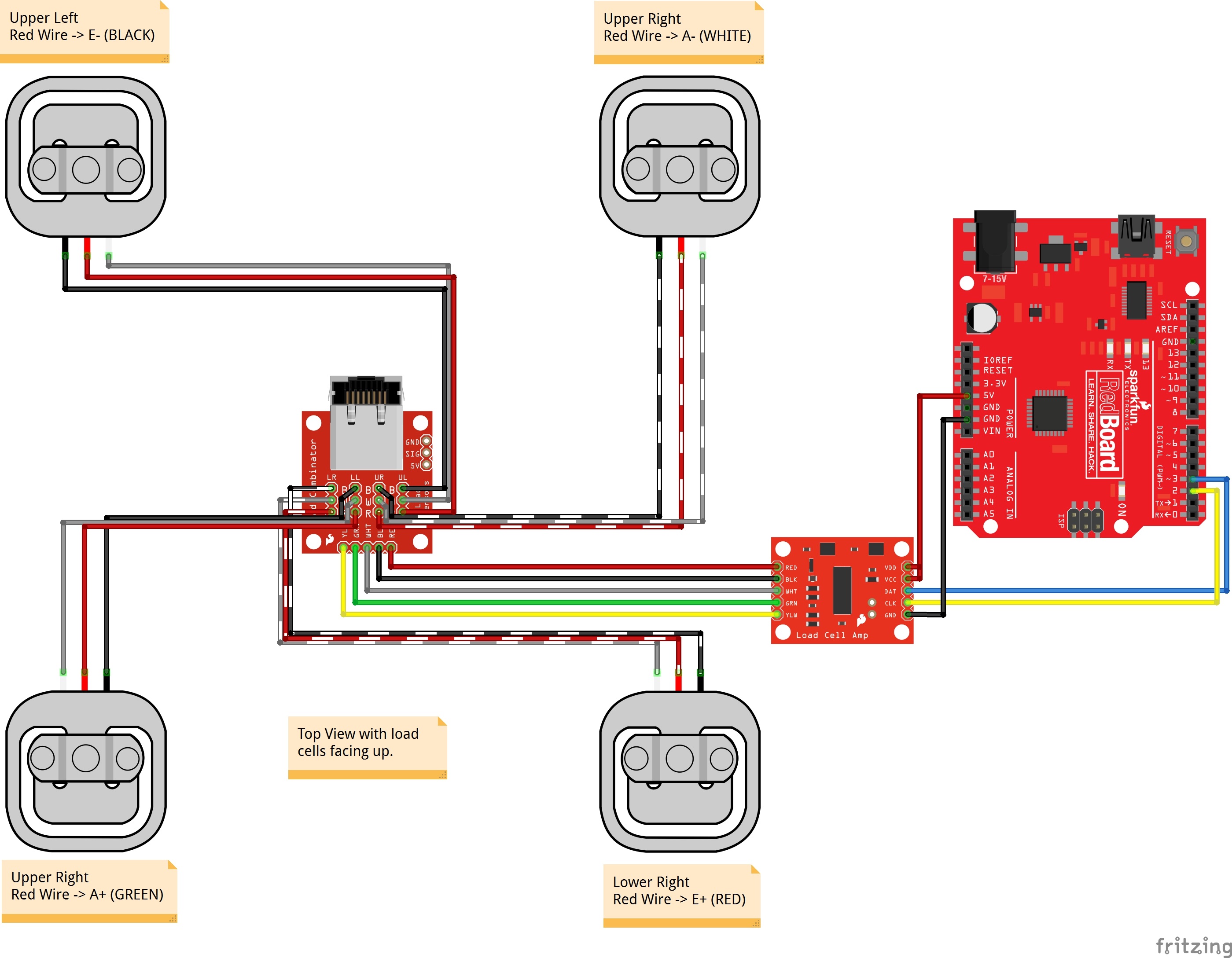
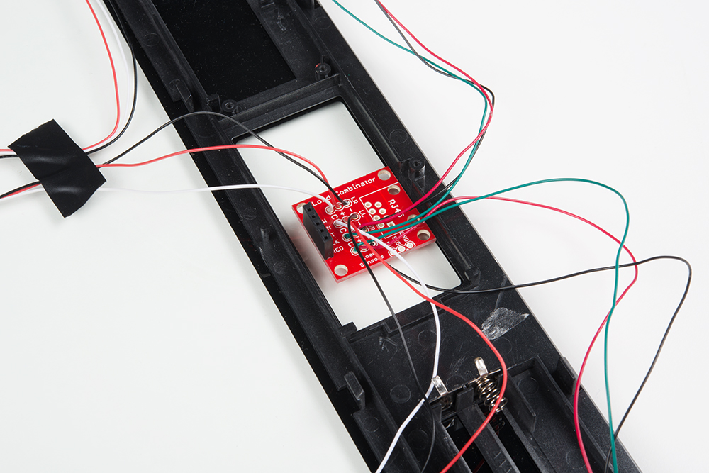
When finished, your setup should look similar to the image below. Make sure to secure the wires before placing it in an enclosure.