Design and build time: 1 Day
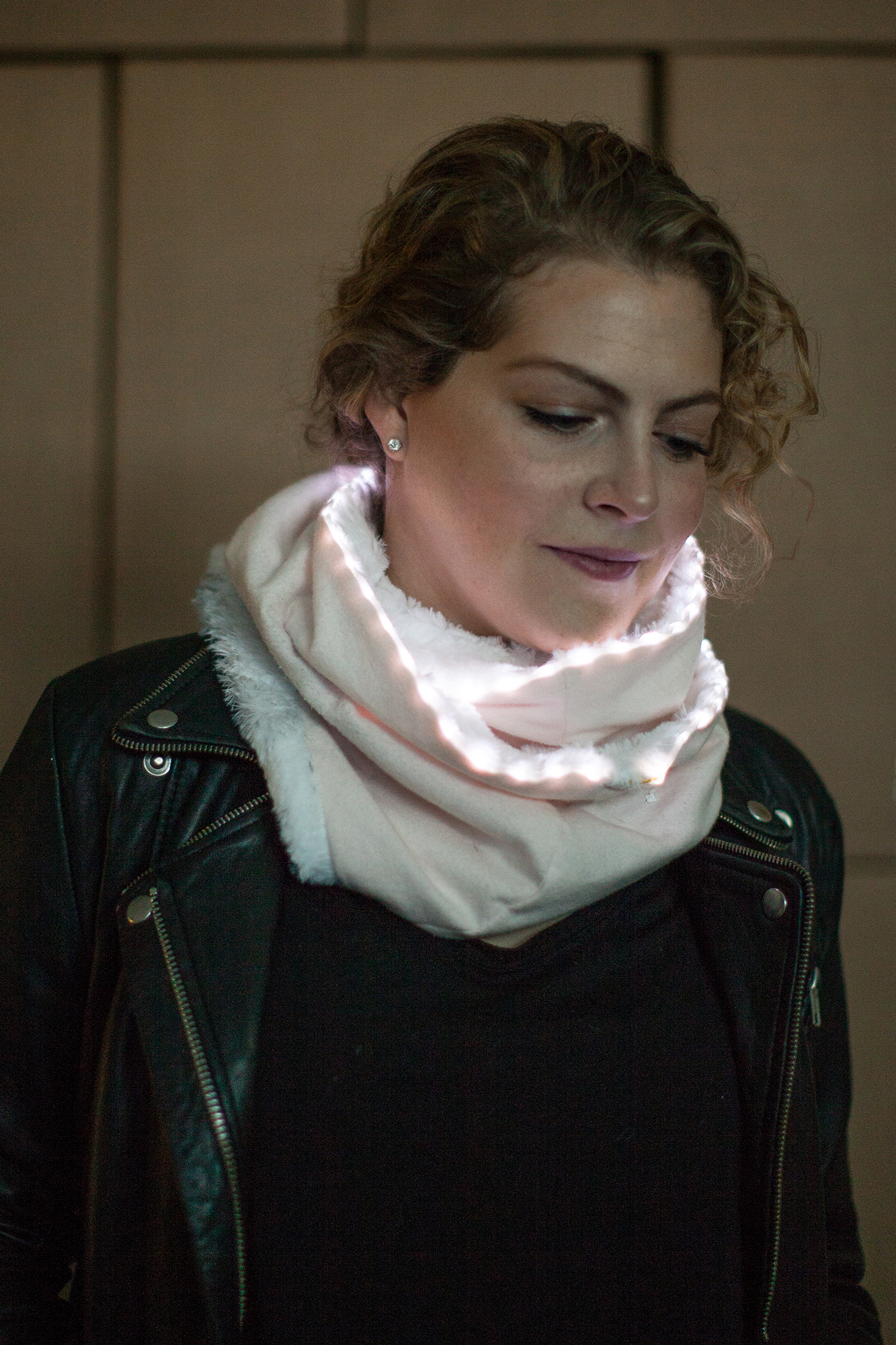
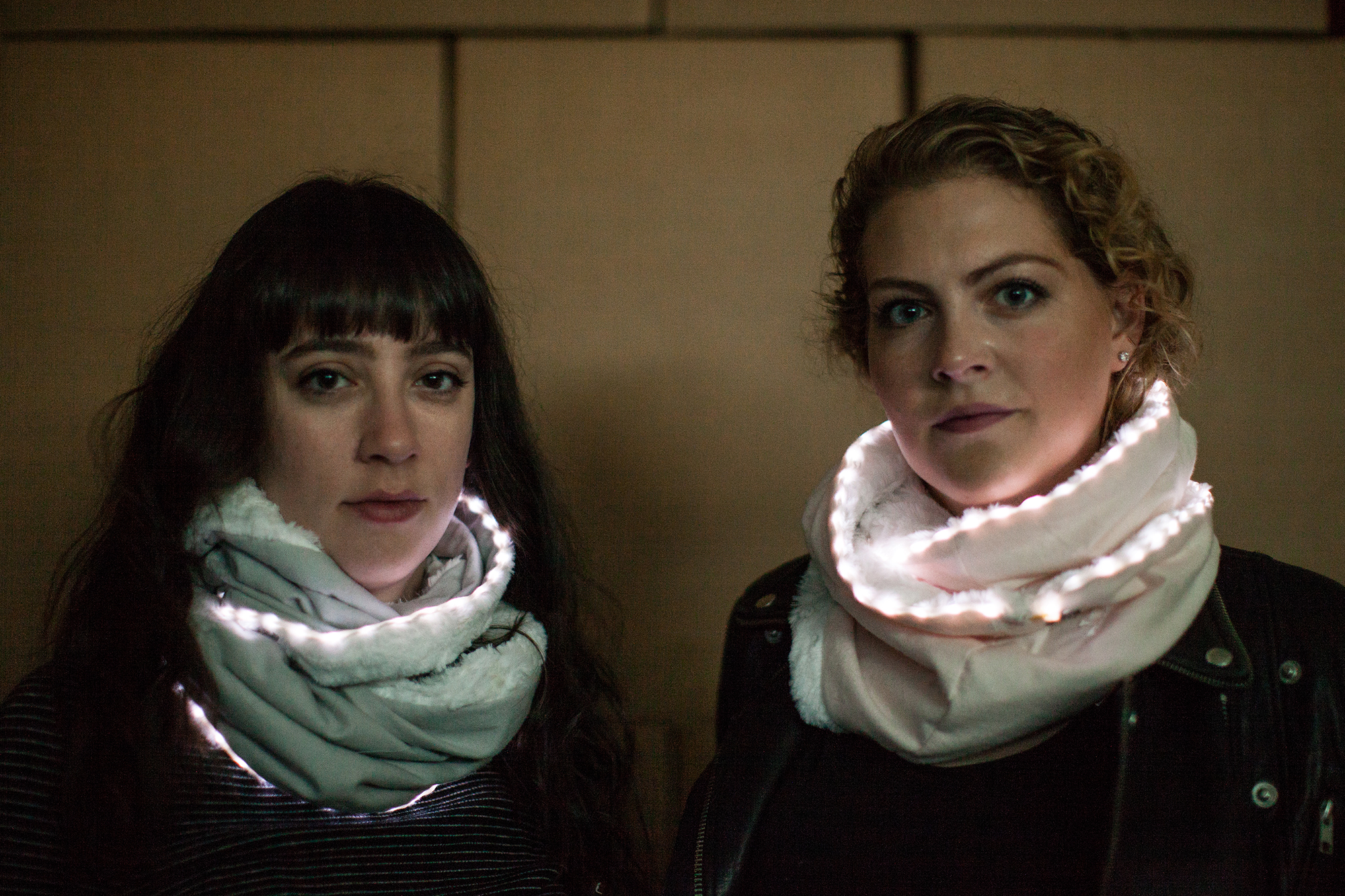
In this project, we’ll create a wearable safety scarf. The safety scarf is embedded with LilyPad Hardware and a ribbon of LEDs. It is designed for pedestrians to increase visibility when walking the streets at night. The LED ribbon is triggered when light is low, making the wearer more visible to vehicles, bikers, and other pedestrians.
Before you get started, take some time to familiarize yourself with the following:
In this project, we will also be following a free sewing pattern from Purl Soho which can be found here.
Let's go over all of the things you'll need to put your project together.
Learn more about e-sewing basic techniques here.
The LilyPad Safety Scarf is an example of a sewable embedded circuit. For this project, we will use a LilyPad USB Plus from the LilyPad ProtoSnap Plus and LilyPad Light Sensor (there is also one included on the ProtoSnap plus that can be used) as well as two LED Ribbons. This project will be powered with an 850 mAh LiPo battery.
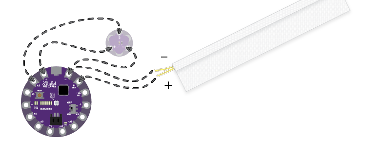
As expressed in the circuit diagram below, the sewable microcontroller is connected to a sewable light sensor via conductive thread. The light sensor has three connections, VCC, GND, and 'S'. VCC and GND connect to '+' and '-', respectively. The 'S' tab should be connected to pin A2 on the microcontroller.
The LED ribbon will be handled differently. While the ribbon itself can be sewn onto a garment, the electrical leads are not sewable - just traditional wires. Luckily, the LilyPad Sew tabs are also solder friendly. So in this instance, we will solder the LED lead's soft, flexible wire to the microcontroller. The datasheet for the LED ribbon indicates that the anode is copper colored (i.e. reddish brown) and the cathode is a silver color (i.e. metallic grey). Connect the anode to pin 11 on the LilyPad USB Plus and the cathode to the GND pin labeled '-'.
The LilyPad USB Plus is programmable via the Arduino IDE. If this is your first time using Arduino, please review our tutorial on installing the Arduino IDE.
If this is your first time working with the LilyPad ProtoSnap Plus, you will need to add the board through the boards manager to your program. Please visit the LilyPad ProtoSnap Plus hookup guide for detailed instructions on installing drivers and programming a LilyPad via the Arduino IDE.
Note: This example assumes you are using the latest version of the Arduino IDE on your desktop. If this is your first time using Arduino, please review our tutorial on installing the Arduino IDE.
We have provided the code for this project below. Copy and paste it into your Arduino IDE and then upload it to your board. Make sure you have the correct board selected in the boards manager as well as the port under the port drop down.
language:c
//Melissa Felderman for SparkFun Electronics 2017

//variable for sensor pin
int sensorPin = A2;

//variable for light value
int lightValue;

//variable for LEDPin
int LEDPin = 11;

void setup()
{
    // Set sensorPin as an INPUT
    pinMode(sensorPin, INPUT);

    //set LEDPin as OUTPUT
    pinMode(LEDPin, OUTPUT);


void loop()
{

   // Get the current light level
    lightValue = analogRead(sensorPin);

    //if light level is low, turn LEDS on
    if(lightValue <= 15){
      digitalWrite(LEDPin, HIGH);

    }
    //if light is high, turn LEDs off
    else {
      digitalWrite(LEDPin, LOW);
    }


}

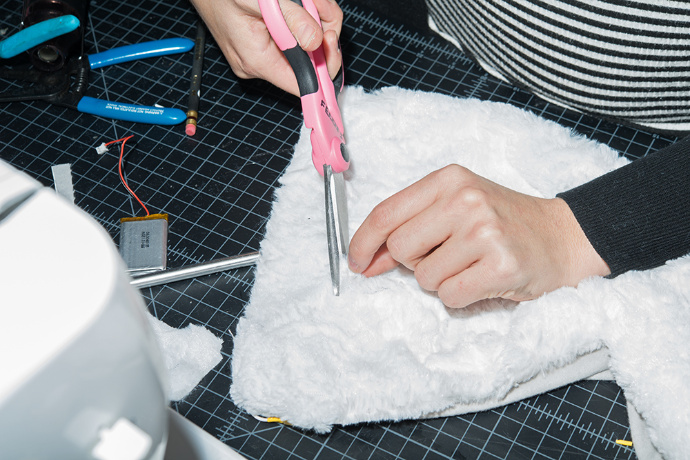
Use an X-Acto Knife to cut the fabric around the LEDs back about one inch on one side of both of your LED ribbons.
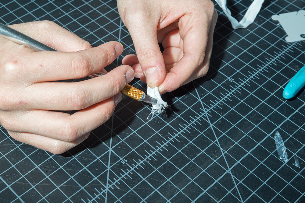
This will cause the ribbon to fray at the end.

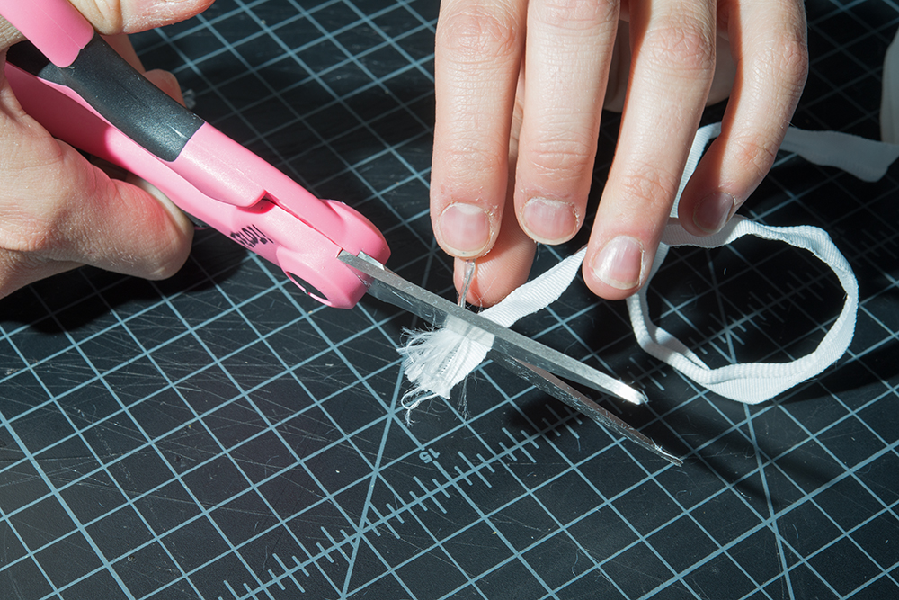
Pull back the wires and use a pair of scissors to cut off the frayed material. Make sure not to cut the LED's wires.
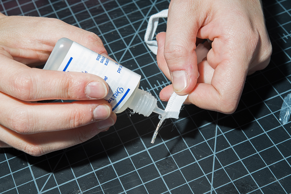
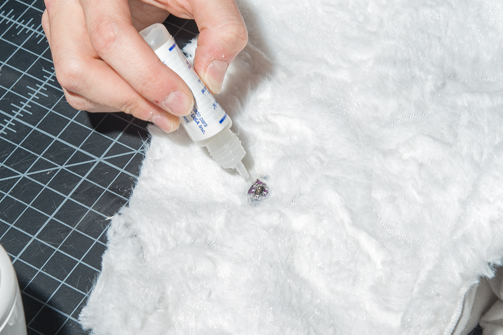
Apply Fray Check to the cut edge of each ribbon, and let it dry (~15 minutes).
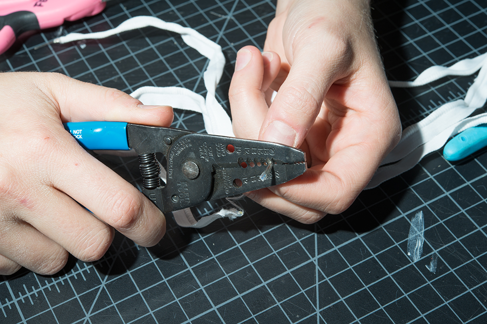
Strip the exposed wire of LED strip. Notice one lead has a copper tint and one does not. The copper tinted lead is the anode, or '+' lead. For more information about polarity and LEDs, visit our tutorials about polarity and LEDs.
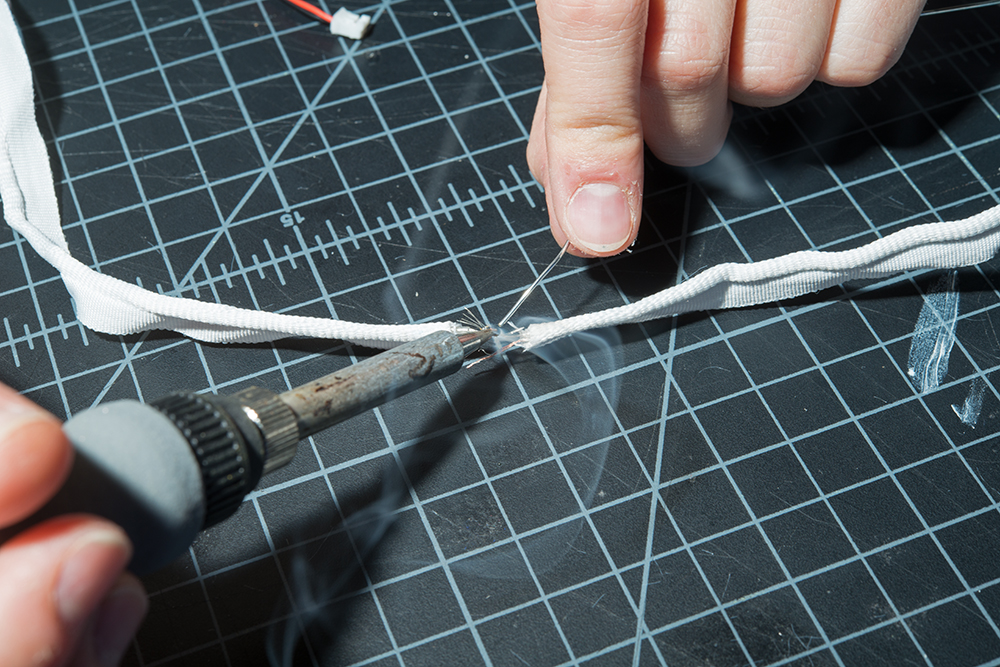
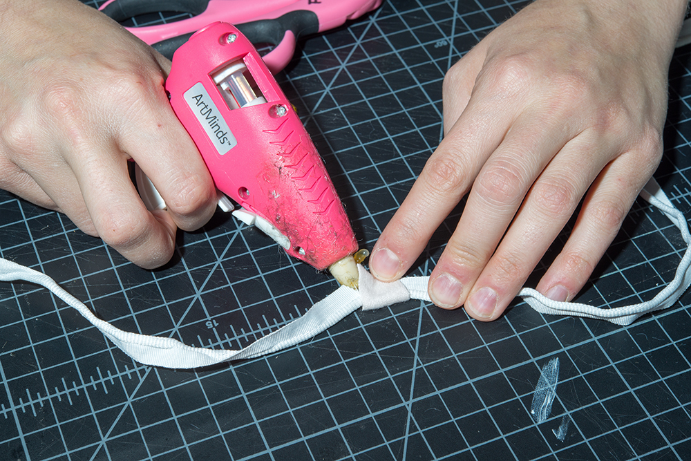
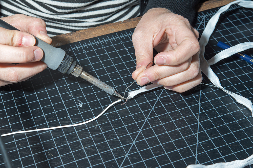
Solder the two LED ribbons together. This can be tricky with the LED ribbons since there is no room to add heat shrink and the frayed wires can easily become crossed. To battle this, I soldered my anodes first and left a little space between the two ribbons. Then, I insulated them with hot glue before soldering the cathodes together. Make sure to insulate the cathode side after soldering them together.
Cut a small rectangle of white felt. Fold it over the ribbon to hide the solder connections we just made. Hot glue it in place.
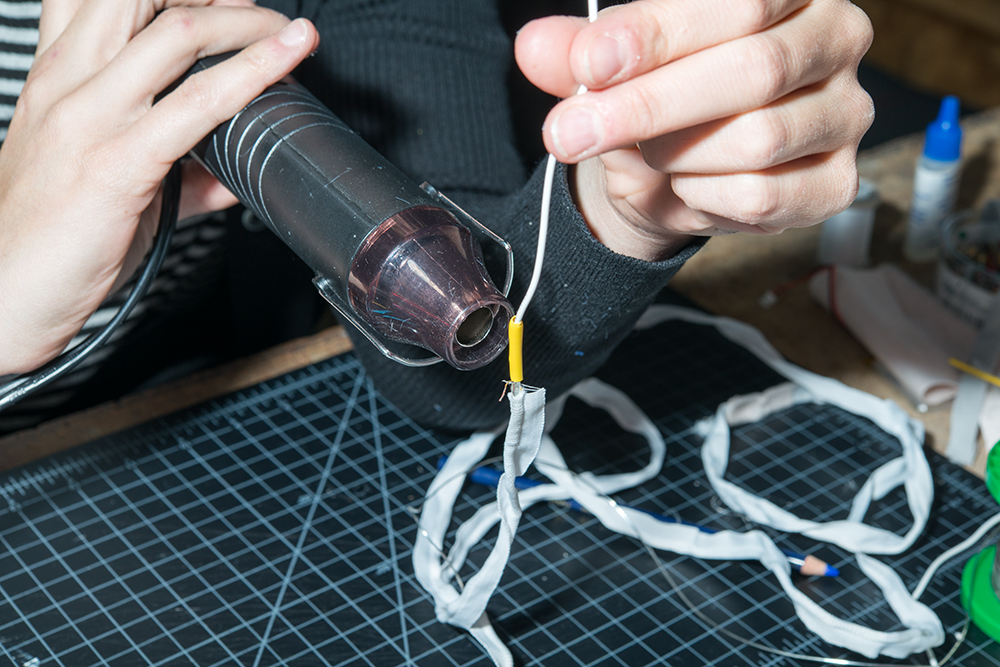
You should have one long LED ribbon now. Repeat steps 1-4 on only one end of the new long ribbon. Cut about two 4-5 inch pieces of flexible silicone wire, soldering one to the exposed anode and one to the exposed cathode.
Insulate with heat shrink and then set aside for later.
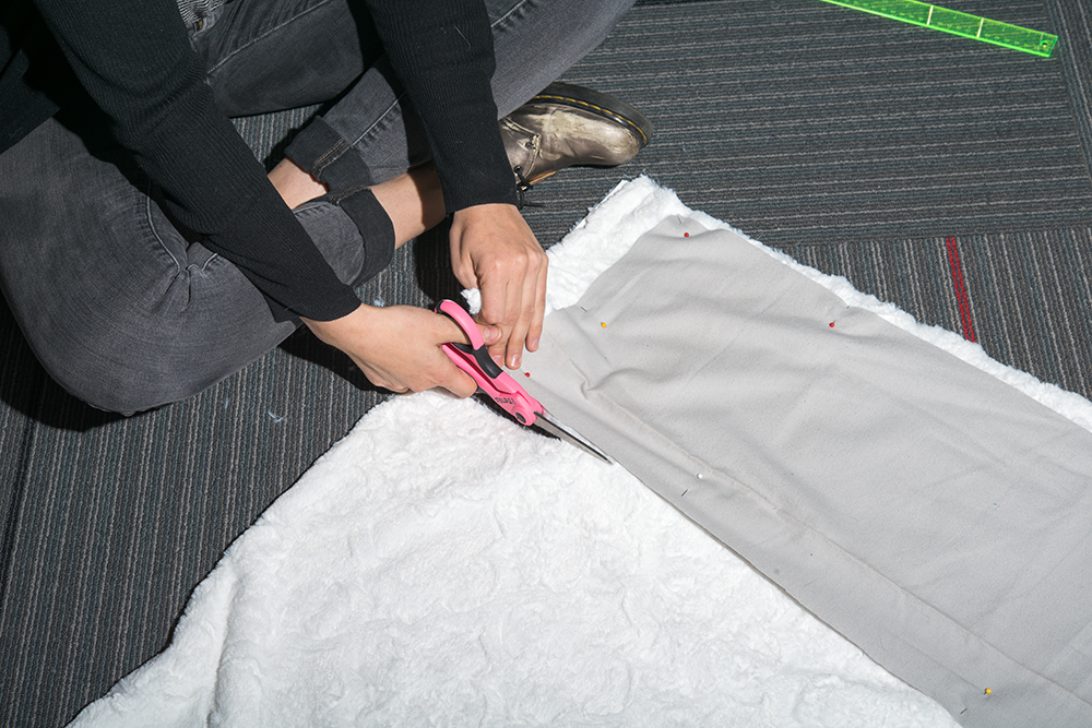
Cut your fabric according to the pattern. We used this lovely and easy to follow free cowl pattern by Purl Soho.
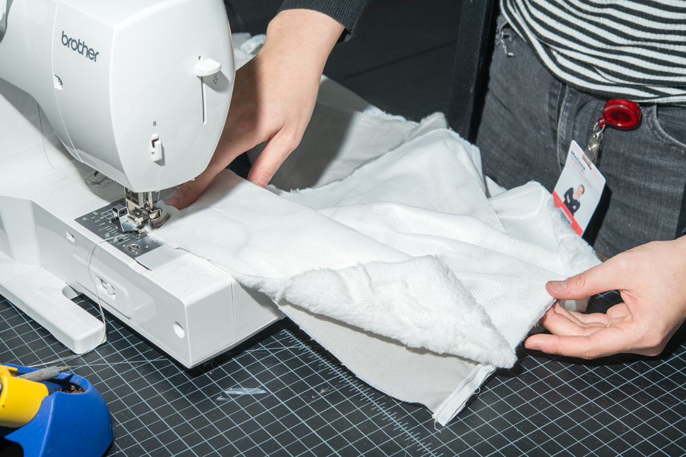
Sew the lining pieces together. Then sew the outer pieces together, but stop before sewing the lining and the outer fabric together. Set the lining aside for later.
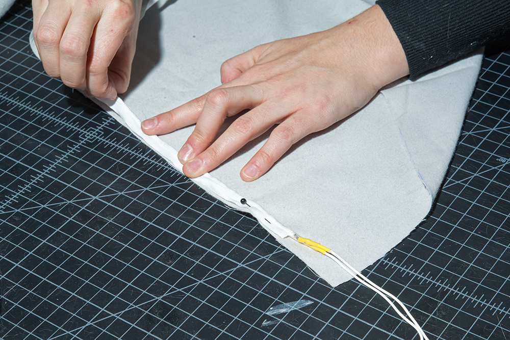
Find the "right side" of the outer fabric. The right side is the side that will be facing the world when you wear the garment. Grab the LED ribbon, and pin it to the long edge of your outer fabric on the right side. The sew tab should be along the top edge of the fabric with the tube holding the LED strip pointing towards the center of the fabric as seen in the image below.
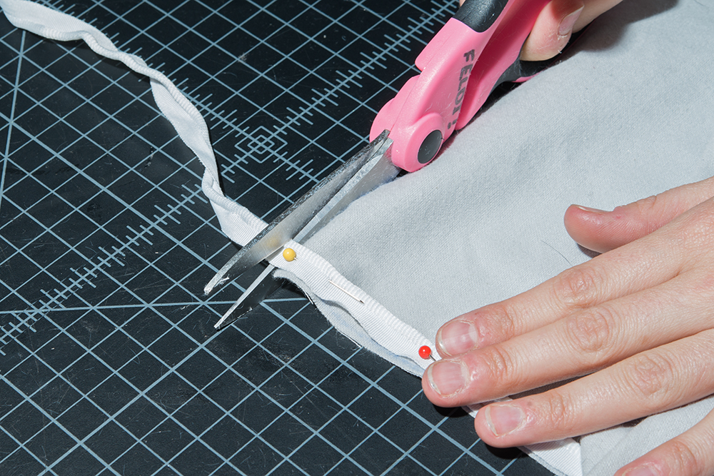
When you reach the end of your fabric edge, cut the strip to the same length of the fabric.
Add a touch of Fray Check to the edge of LED ribbon that you cut.

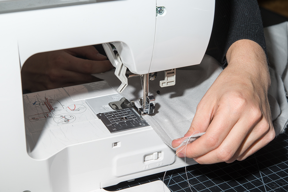
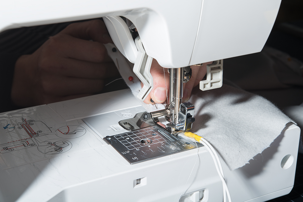
Sew the LED ribbon down along the sew tab. Make sure to remove the pins as you go since this can break your sewing machine needle and cause problems with your stitch. When using a sewing machine, be careful to not sew into the LEDs and wires.
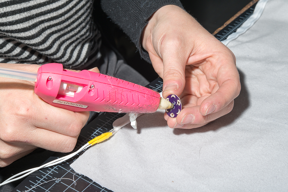
Add a dab of hot glue to the bottom of your LilyPad Light Sensor and then place it on the right side of your fabric about an inch below the LED ribbon leads.

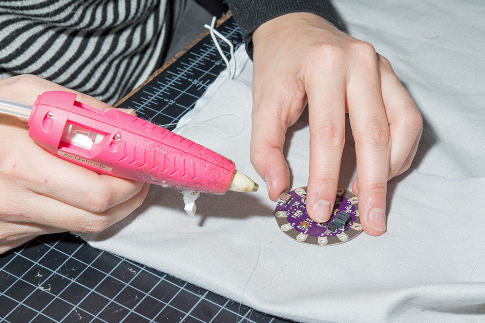
Flip the fabric over to the "wrong side." The wrong side will be the inside of the cowl. Add some hot glue to the bottom of the LilyPad USB Plus and place it down about 1-2 inches below the light sensor (but on the opposite side!)

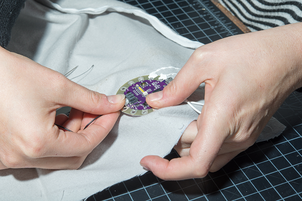
Using conductive thread, sew the light sensor to the microcontroller according to the circuit diagram.
Strip the un-soldered side of both flexible silicone wires connected to the LED leads.

Solder the anode ('+') lead connection to pin 11 on the LilyPad and the cathode ('-') lead to GND on the LilyPad.

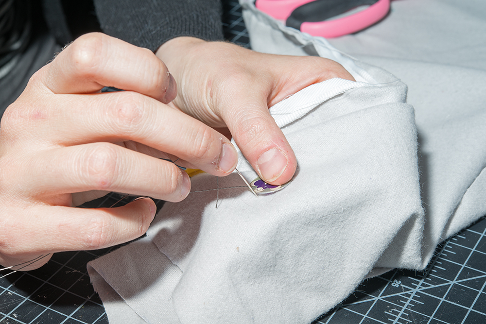
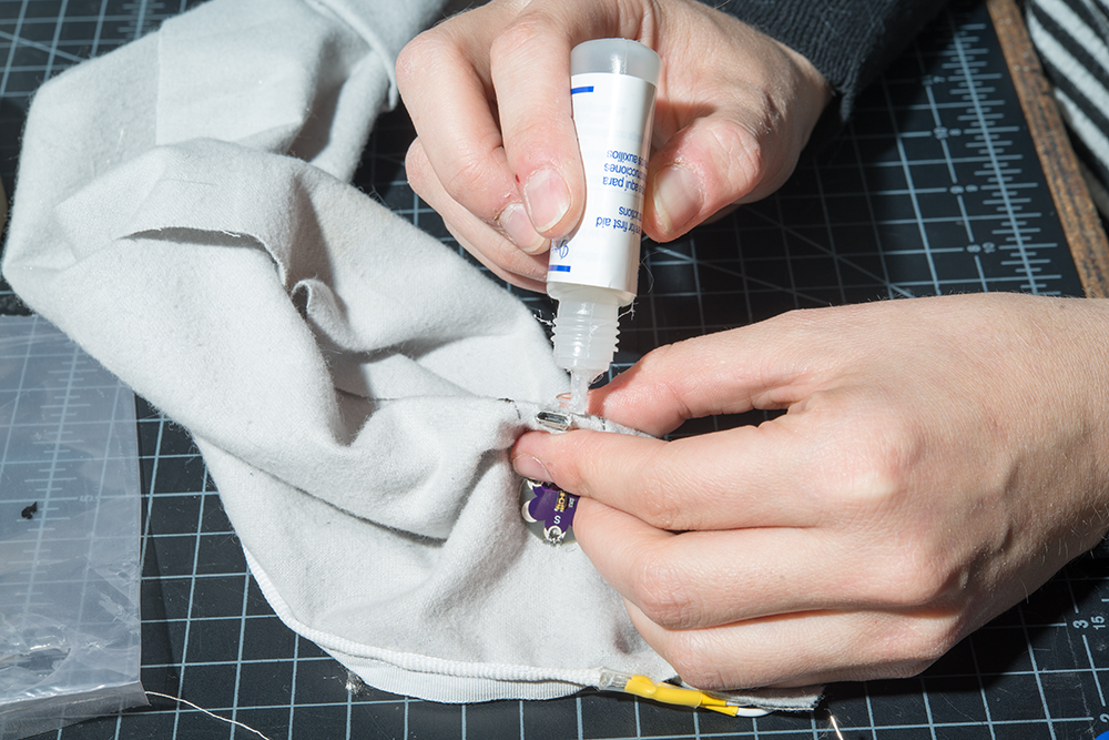
Cut a small hole directly above the USB cable connector. Make sure it is large enough to access that port from the opposite side of the fabric.
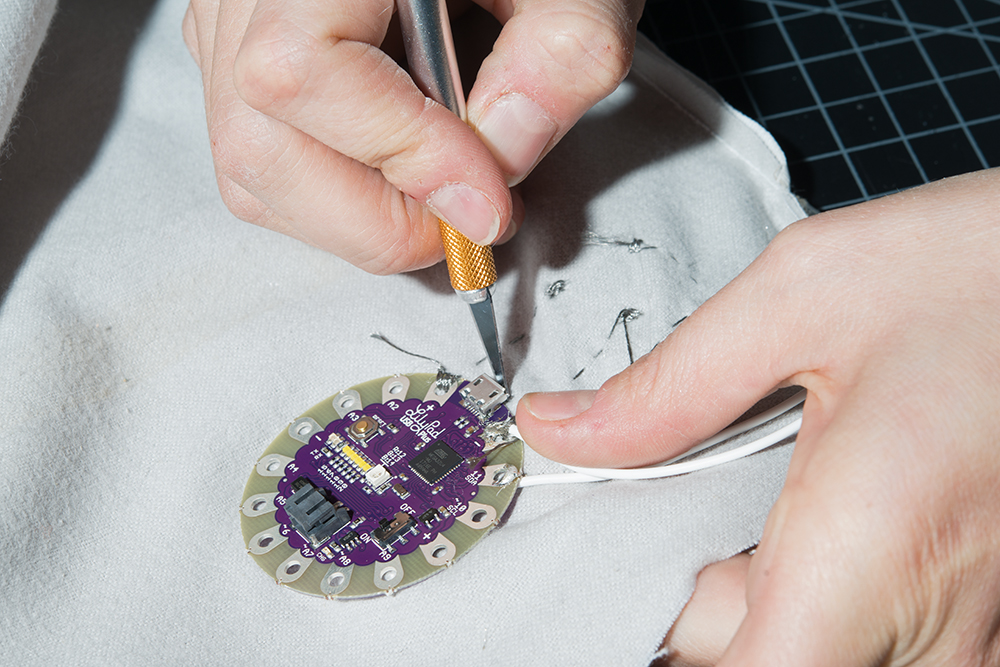
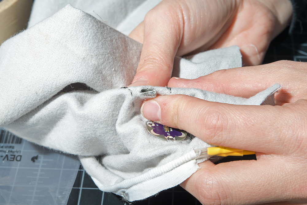
Apply Fray Check around the cut edges of the hole. Make sure that the Fray Check does not get into the USB connector.
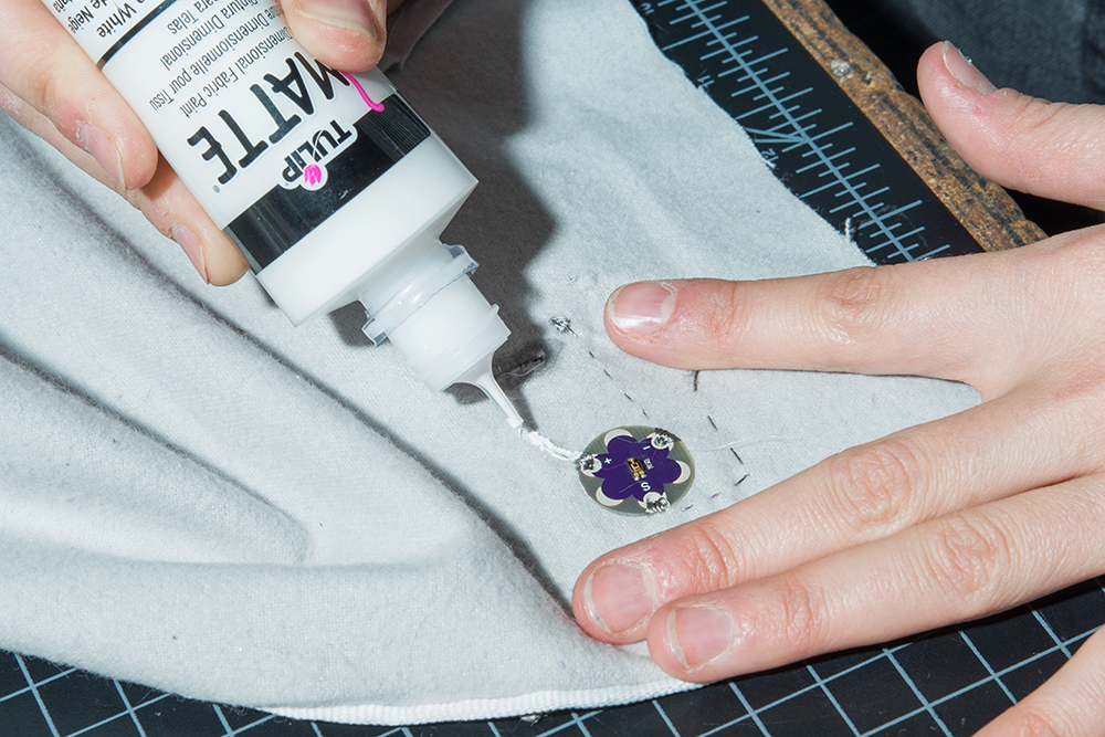
Trim the excess conductive thread and test your circuit with a battery. Once everything is working, use some puff paint to insulate the traces on both the right and wrong side of the fabric.
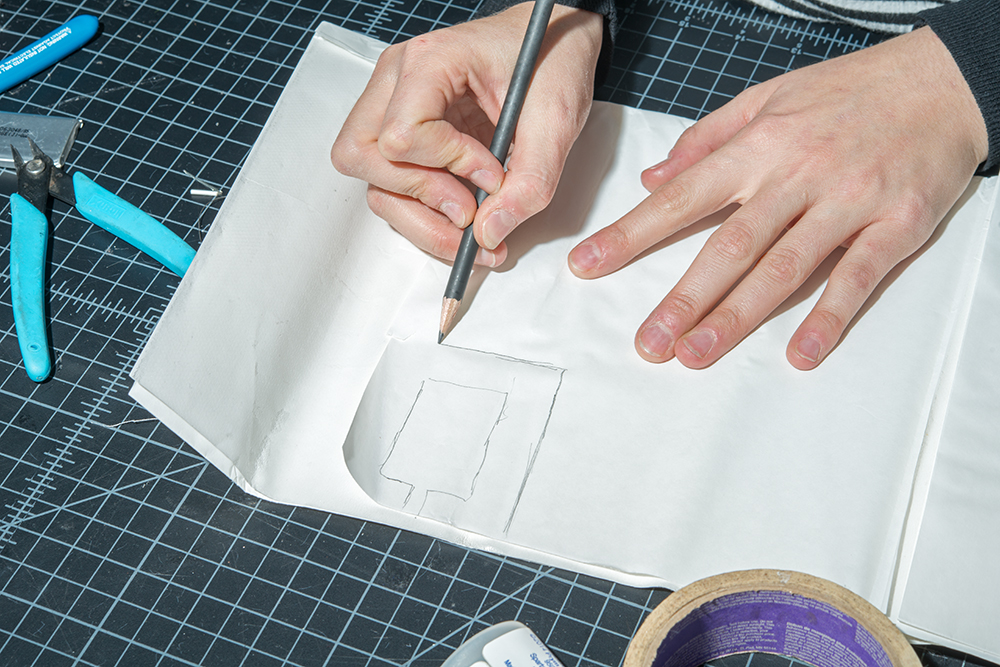
Place your battery on the iron-on adhesive and trace it.
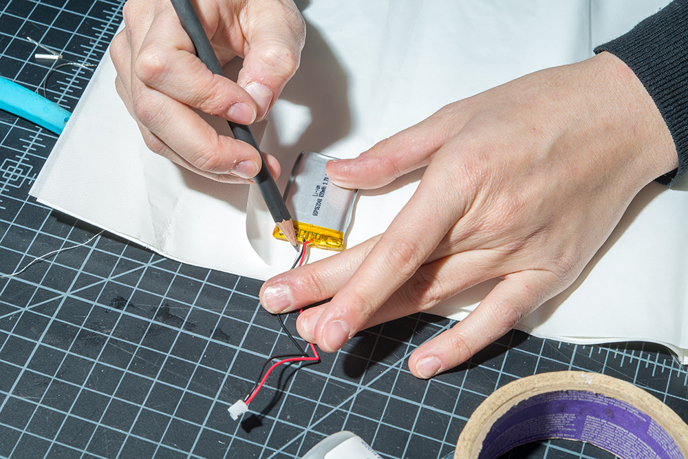
Draw a larger rectangle around the battery's trace and leave at least a half inch space between the lines.
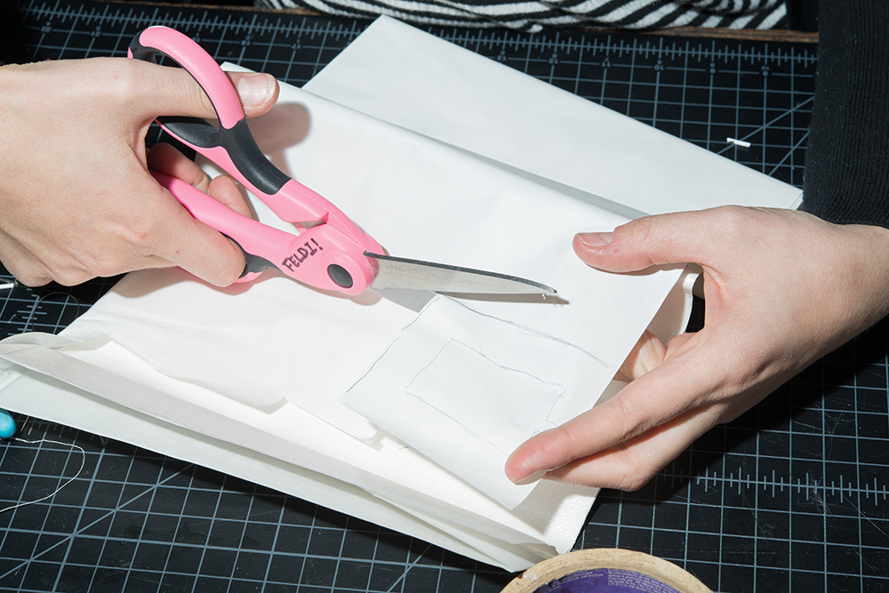
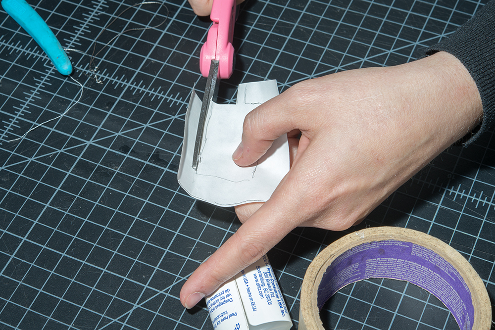
Cut along the edge of the larger rectangle, and then cut out the battery tracing as well.
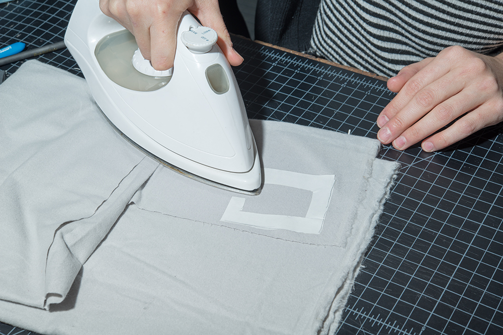
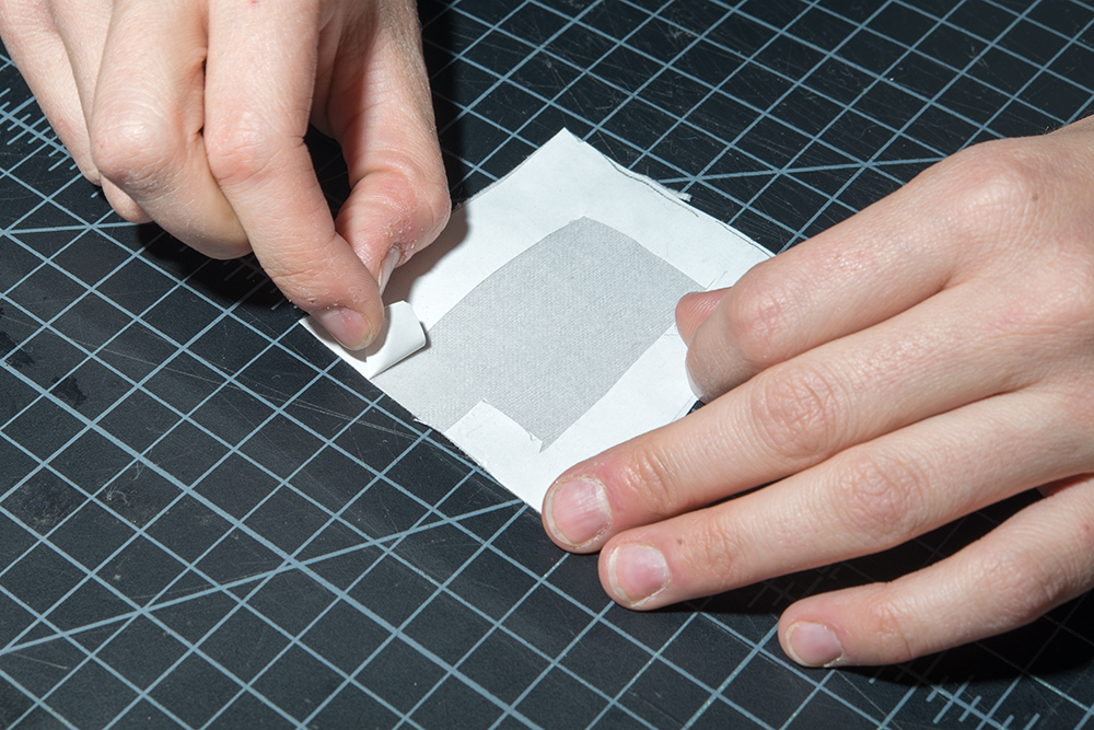
With the paper side up, iron the iron-on adhesive to a scrap piece of fabric. Then cut the fabric along the edge of the adhesive.

Peel the paper backing off of the iron-on adhesive.
Plug your battery into the LilyPad's JST connector.
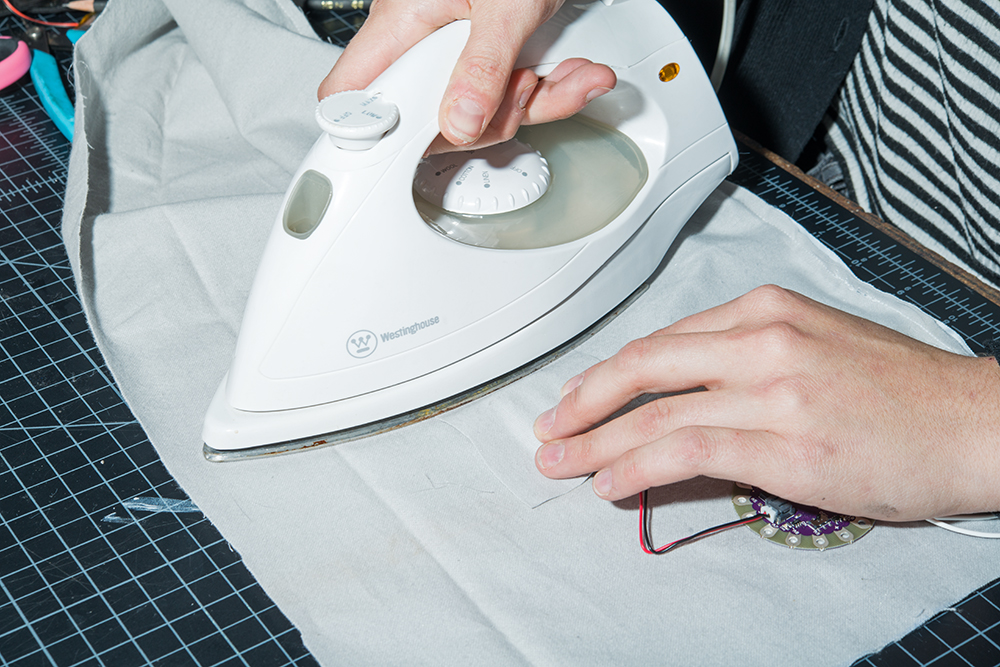
Place the piece of fabric with the iron-on adhesive over of the battery. Make sure that the adhesive side is facing down.

Being extremely careful to not touch the battery, and iron over the fabric where there is adhesive in order to make a battery holder.
Finish sewing the scarf according to the pattern.
Use your finger to feel for the ON/OFF switch on the LilyPad and then cut a small hole in the lining fabric to expose it.
Add some Fray Check around the edge of the hole, and let dry.
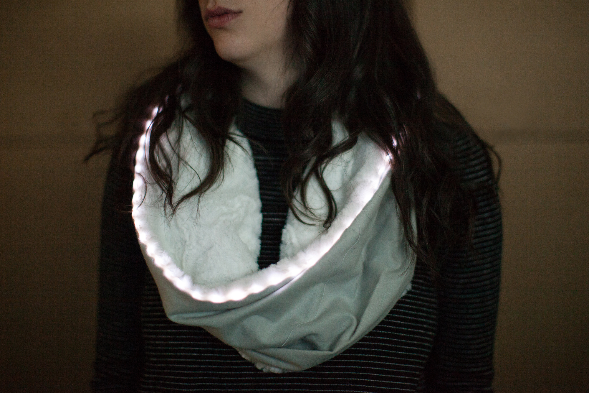
Turn it on by flipping the switch and enjoy!
Looking for another project? Check out these similar projects for inspiration!
learn.sparkfun.com | CC BY-SA 3.0 | SparkFun Electronics | Niwot, Colorado