Level Shifter - 8 Channel (TXS0108E) Hookup Guide
 El Duderino
Hardware Assembly
In this section we'll demonstrate how to assemble this breakout into a level-shifting circuit between a 5V development board, the RedBoard Plus, and a 3.3V SPI device, the SparkFun Triple Axis Accelerometer Breakout - KX134 (Qwiic). We'll use a breadboard here to make building the level shifting circuit easier and to keep the connections as short as possible.
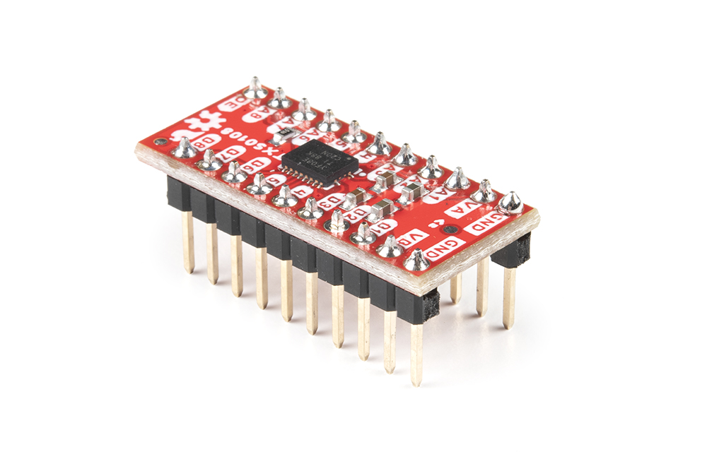
Soldering Assembly
This breakout requires some through-hole soldering to integrate the board into a level-shifting circuit. Since the demo circuit uses a breadboard we'll solder a set of breakaway male headers to the board so we can easily plug it into the breadboard.
Arduino Assembly
Plug the Level Shifter Breakout into the breadboard and then make connections to the board with wires. Leave the circuit unpowered while building the circuit to avoid damaging anything with a short or improper connection.

Reminder, VCC_A must be less than or equal to VCC_B and OE needs to connect to VCC_A. Our SPI device runs at 3.3V so we connect the peripheral pins to channels on Port A and connect matching microcontroller signals to Port B.