INA169 Breakout Board Hookup Guide
 Shawn Hymel
 Introduction
Have a project where you want to measure the current draw? Need to carefully monitor low current through an LED? The INA169 is the chip for you!
The INA169 is a "high-side current monitor," which means that you place a resistor (a "shunt resistor") on the positive power rail and the INA169 measures the voltage drop across that resistor. The INA169 outputs a small current based on the measured voltage drop. If you place a resistor from the output of the INA169 to ground, you can measure the voltage at the output. With some basic math, the output voltage gives you the current through the shunt resistor.
Covered In This Tutorial
In this tutorial, we cover how the board should be used. The Board Overview section covers some theory and math on how the current sensing works, so feel free to skip to the Hookup Example if you just want to see the board in action. The Hookup Example shows how to connect the board to an Arduino in order to measure the current through an LED, and the Example Code provides a quick Arduino sketch for displaying the measured current to the Serial Monitor.
Required Materials
- Arduino, RedBoard or any Arduino-compatible board.
- Male headers to solder to the board and make it breadboard compatible.
- Jumper wires to connect from breadboard to Arduino.
- Breadboard to tie everything together.
- Basic Red LED so we have something to light up.
- 330Ω Resistor to limit the current through the LED.
Suggested Reading
Board Overview
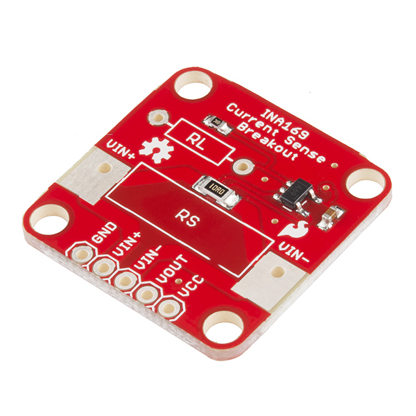
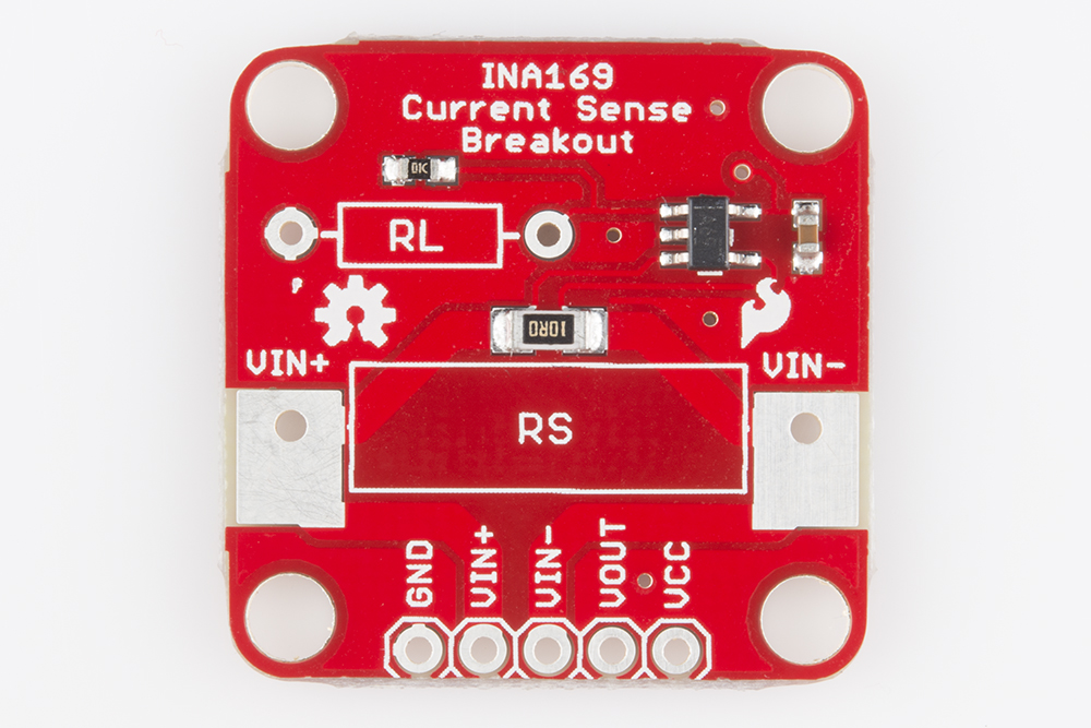
Take a look at the schematic, and you will notice that the breakout board consists of a shunt resistor (RS), the INA169 chip, and an output resistor (RL). While RS and RL might appear to have 2 resistors, only one is populated on the board. If you would like to change the values of the resistors, you can replace them or put another resistor in parallel.
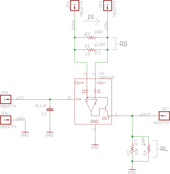
As current passes from VIN+ through RS to VIN-, it creates a voltage drop across RS. The op-amp inside of the INA169 chip measures the difference between the VIN+ and VIN- voltages and outputs a voltage based on that difference. The output of the op-amp is amplified through the internal transistor, which sources a current out of the INA169 chip. As that current passes through RL to ground, a voltage level is generated at VOUT.
Measuring Current
The voltage at VOUT can be measured using an oscilloscope or an analog-to-digital converter. A bit of math is needed to convert to the source current (IS):
IS is the current we want to measure.
VOUT is the voltage we measured at the output of the INA169.
1kΩ is a constant resistance value we need to include due to the internals of the INA169.
RS is the value of the shunt resistor. If you do not modify the board, then this is set at 10Ω.
RL is the value of the output resistor. If you do not modify the board, then this is set at 10kΩ.
Example
For example, let's say that you hook up the board and you measure 2.8V at VOUT. Plugging this into our equation, we would get:
This shows that you have 0.028A (or 28mA) flowing through your line.
The Pinout
There are only 5 pins on the breakout board.
GND should be connected to ground of the circuit you are trying to measure
VIN+ needs to be connected to the positive side of the source (e.g. battery, output pin, etc.)
VIN- needs to be connected to the positive side of the load (e.g. VCC on Arduino, positive side of an LED, etc.)
VOUT is the measured output and should be connected to something that measures voltage levels, such as a multimeter, oscilloscope, or an Arduino ADC pin
VCC is the supply power to the INA169, which needs to be connected to 3.3V, 5V, etc. This can be anywhere from 0 to 75V. Note that the VOUT range depends on the voltage supplied by VCC.
In addition to the pins on VIN+ and VIN-, the board also has two large pads around RS, which are capable of taking alligator clips should you want to have a temporary hookup. Note that GND and VCC will still need to be connected for the board to function.
Modifying Functionality
The INA169 cannot sense any differences across RS greater than 500mV, and the output error increases once the voltage across RS dips below 35mV. If you include the voltage drop across the internal transistor, this means that the default setup of the breakout board is limited to measuring a current range of about 3.5mA to 35mA.
If you would like to change that range, RS and RL can be replaced with resistors of different values. RS can be removed and replaced with another resistor fairly easily. RL is a bit more difficult as it is a small, surface mount resistor. Changing either of the resistors changes the equation from above.
With RL at 10kΩ, changing RS gives us the following ranges:
| RS | Current Sense Range |
| 10Ω | 3.5mA - 35mA |
| 1Ω | 35mA - 350mA |
| 0.1Ω | 350mA - 3.5A |
- Ohmite 1Ω 1% 3W
- Ohmite 0.1Ω 1% 3W
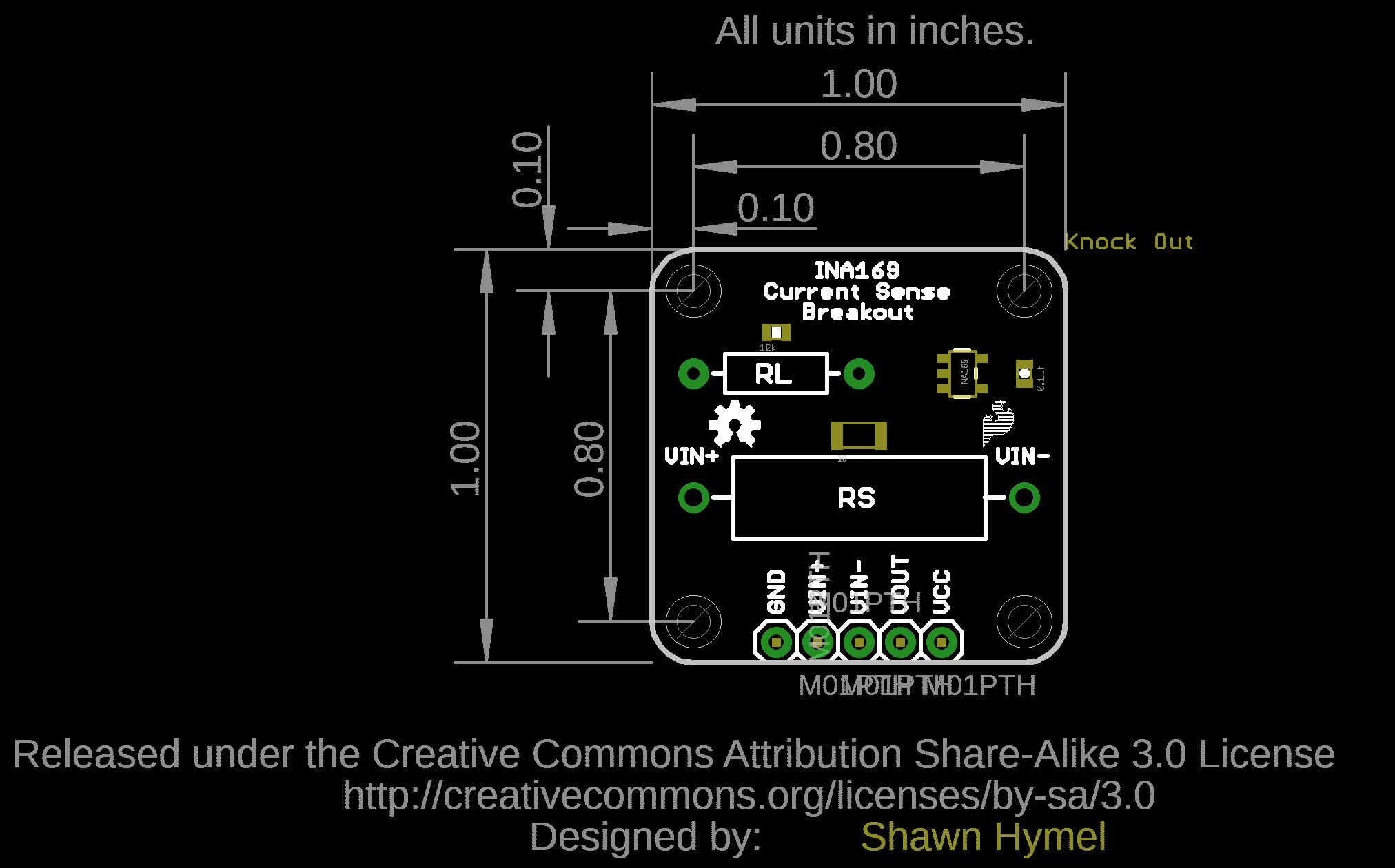
Board Dimensions
The board dimensions is 1.0" x 1.0" and includes 4x mounting holes by each corner of the board.
Hookup Example
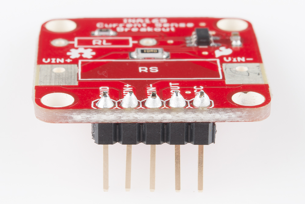
Assembly
You will need to solder either wires or straight male headers to the 5 header holes on the board. If you need to measure over 35mA, you will need to desolder the RS resistor and solder a lower value (e.g. 1Ω), higher power (e.g. 3W) resistor to the holes around RS.
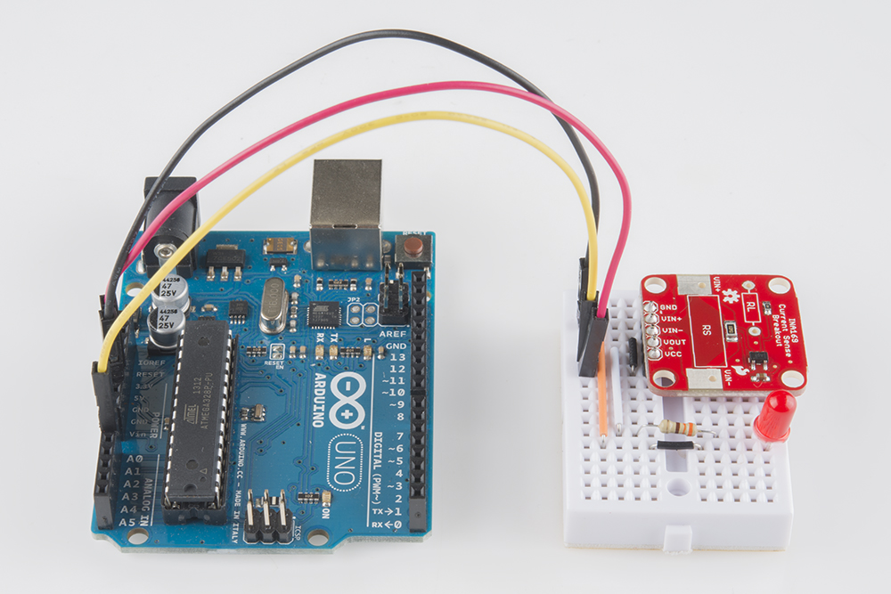
Connecting the INA169 Breakout Board
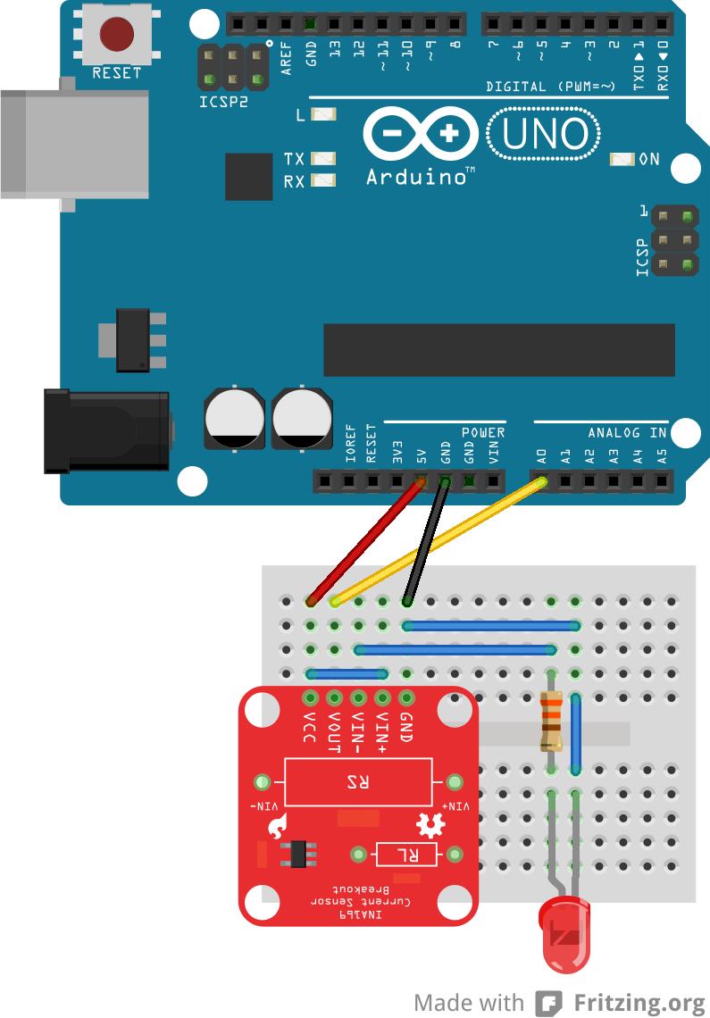
As shown in the diagram, connect the Arduino 5V to the INA169 VCC and the Arduino GND to the INA169 GND. To read the output voltage level, we need to run a jumper cable from the Arduino A0 to the INA169 VOUT pin.
Use a jumper wire to connect the INA169 VCC and VIN+ pins, as we want to power the LED with the Arduino 5V. If you use a different power source (other than the Arduino 5V or 3.3V) through VIN+ and VIN-, make sure you connect the ground of the power source to the ground of the INA169 board. Just ensure that the voltage level as measured from VIN+ to ground does not exceed 60V. Bad things will happen to the board if you do.
Connect a 330Ω resistor from the INA169 VIN- to the anode of the LED and a jumper wire from the LED's cathode to GND.
If you want to measure the current going to something else, you can use alligator clips on the bare metal pads around RS. Make sure that the INA169 board is inline with the positive power rail and that the INA169 GND is connected to the target's GND.
Example Code
Open the Arduino program and paste the following code into the sketch:
language:c
/*
 11-14-2013
 SparkFun Electronics 2013
 Shawn Hymel

 This code is public domain but you buy me a beer if you use this
 and we meet someday (Beerware license).

 Description:

 This sketch shows how to use the SparkFun INA169 Breakout
 Board. As current passes through the shunt resistor (Rs), a
 voltage is generated at the Vout pin. Use an analog read and
 some math to determine the current. The current value is
 displayed through the Serial Monitor.

 Hardware connections:

 Uno Pin    INA169 Board    Function

 +5V        VCC             Power supply
 GND        GND             Ground
 A0         VOUT            Analog voltage measurement

 VIN+ and VIN- need to be connected inline with the positive
 DC power rail of a load (e.g. an Arduino, an LED, etc.).

 */

// Constants
const int SENSOR_PIN = A0;  // Input pin for measuring Vout
const int RS = 10;          // Shunt resistor value (in ohms)
const int VOLTAGE_REF = 5;  // Reference voltage for analog read

// Global Variables
float sensorValue;   // Variable to store value from analog read
float current;       // Calculated current value

void setup() {

  // Initialize serial monitor
  Serial.begin(9600);

}

void loop() {

  // Read a value from the INA169 board
  sensorValue = analogRead(SENSOR_PIN);

  // Remap the ADC value into a voltage number (5V reference)
  sensorValue = (sensorValue * VOLTAGE_REF) / 1023;

  // Follow the equation given by the INA169 datasheet to
  // determine the current flowing through RS. Assume RL = 10k
  // Is = (Vout x 1k) / (RS x RL)
  current = sensorValue / (10 * RS);

  // Output value (in amps) to the serial monitor to 3 decimal
  // places
  Serial.print(current, 3);
  Serial.println(" A");

  // Delay program for a few milliseconds
  delay(500);

}
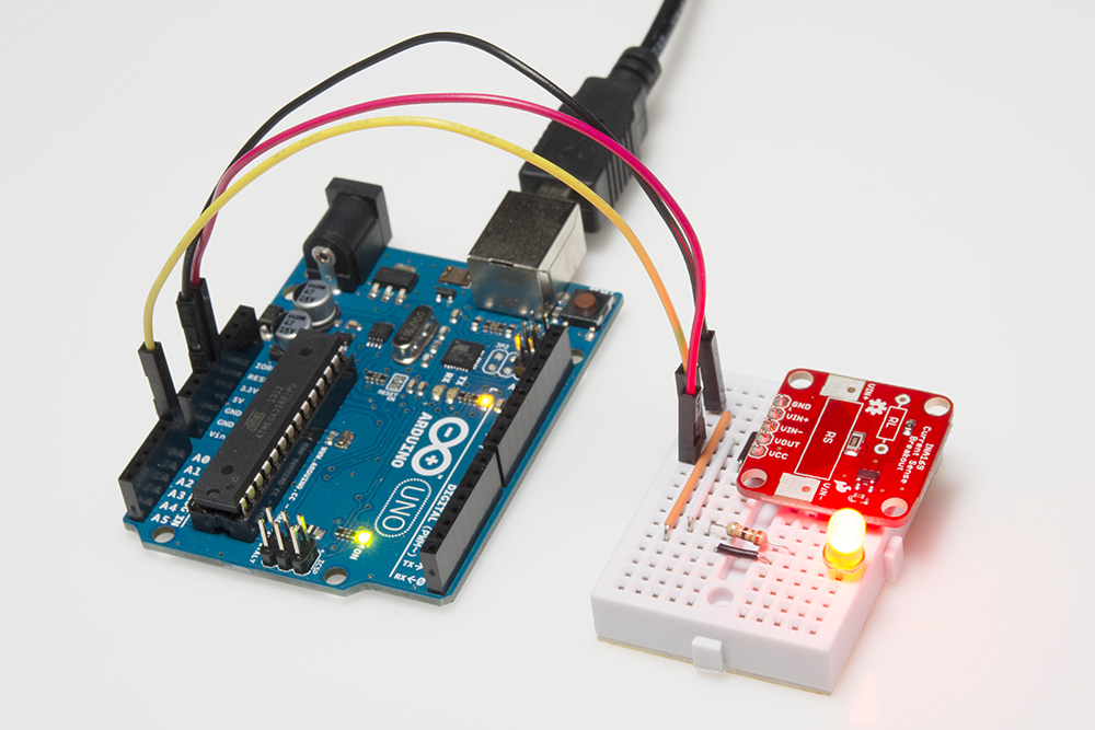
Plug in the Arduino and upload the code. You should see the LED light up as soon as you apply power.
Select the appropriate board (Arduino Uno in this case) from Tools->Board and the correct COM port from Tools->Serial Port. Click the upload button, and wait for the program to be compiled and uploaded to the Arduino. Open the Serial Monitor from Tools->Serial Monitor and you should see current measurements being printed.
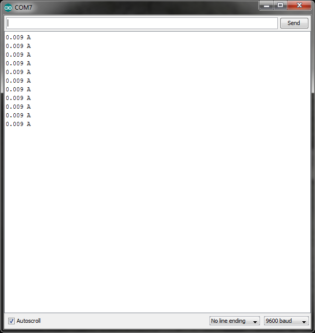
If we want to verify this reading, we can use a multimeter to measure the voltage across the 330Ω resistor. You should see around 3V across the resistor. Using Ohm's Law, we can calculate the current flowing through the resistor and LED is 0.00909 A, which matches the reading from the INA169.
Resources and Going Further
The INA169 is a useful chip if you want to know how much current something is using. For example:
- On The Uncertain 7-Cube, you can connect the INA169 inline with the battery's positive power wire (that's the red wire!) and measure the current draw to figure out how long your battery will last.
- Similarly, connect the INA169 to the HUB-ee Buggy's power and determine how much time you get before you need to replace those AA batteries.
- Or use the INA169 to determine how much power is being consumed if the Humidor Control Box is left on all the time.