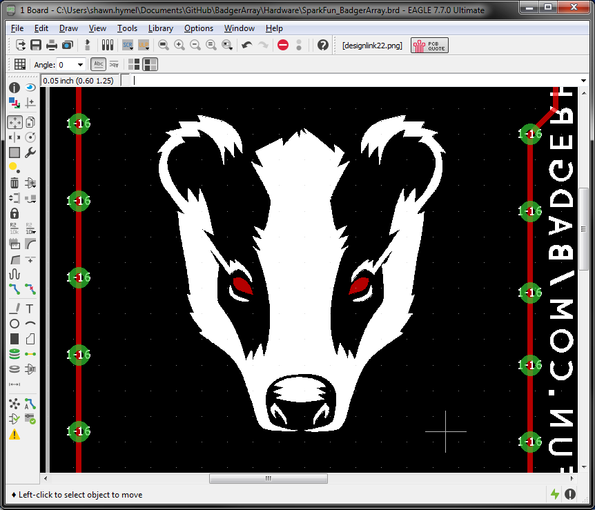
Creating custom artwork on your PCB can be a fun way to personalize your project, add a company logo, or go crazy with pin numbering fonts. In this tutorial, we'll show you 3 different methods of importing custom images into Eagle. Note that each of the three ways has pros and cons.
We recommend trying Method #1 (SVG to Polygon) first. It is the most complicated, but, if it works, you'll have a set of polygons for your custom image that are much easier to work with than the lines/rectangles created by methods 2 and 3. If that fails, try method 2 or 3 to import an image as a series of lines, but be warned that having that many shapes can slow down your computer.
Additionally, you can import an image with method 2 or 3 and then trace over them with polygons in Eagle.
Before starting with this tutorial, we recommend that you be familiar with the basics of Eagle CAD:
Importing a vector graphic directly into Eagle requires a bit of work, but we recommend trying it first because:
If you don't already have it, download and install the latest version of Inkscape. You will need it for this method.
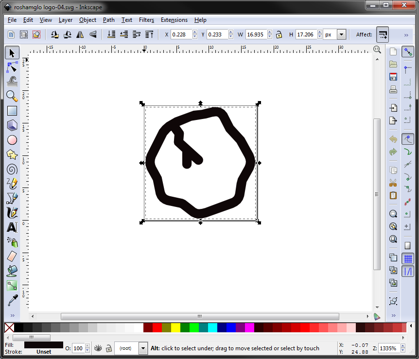
Draw, download, import, etc. your desired image. Make sure it is a single color (we'll use black) and saved as a vector graphic (e.g. SVG). In this example, we'll import an SVG image made with Adobe Illustrator.
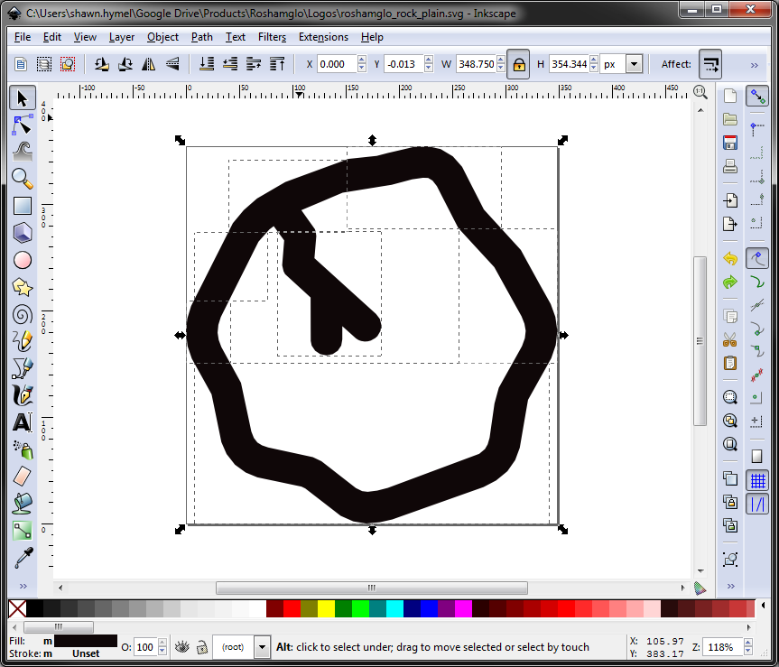
Click the select tool (F1), and select Edit > Select All in All Layers (Ctrl + Alt + a).
Click the button to lock the height/width ratio.

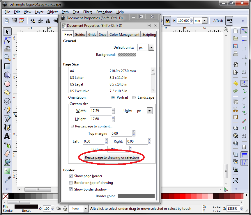
Change the units to mm, and change height to 100.

Go to File > Document Properties..., select Resize page to content... drop down, and click Resize page to drawing or selection.
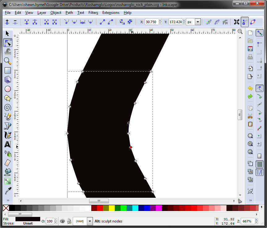
Convert the object to a path and select nodes:
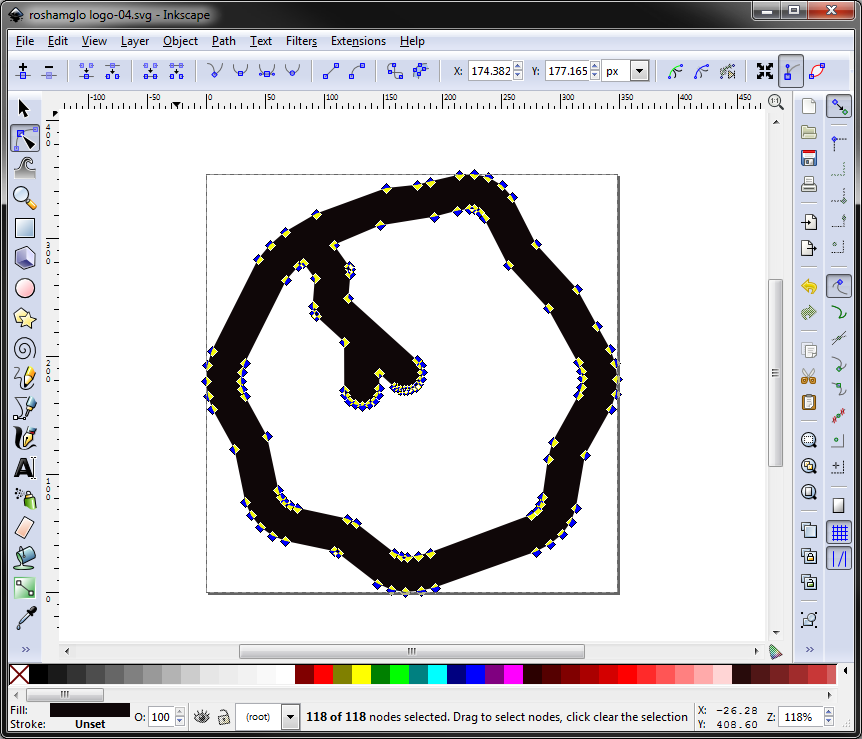
Add interpolated nodes and flatten beziers (we want straight lines for the polygon):

Any shapes that have a closed loop or a "hole," will need to be cut (Eagle doesn't know how to create a polygon with a hole in it).
Draw a shape, such as a rectangle, that divides the hole.

Hold Shift, and select both the rectangle and your image. Select Path > Division (Ctrl + /). Repeat this process for any closed loops in your image, such as donuts, outlines, and letters like 'o' and 'd'. You should end up with a number of paths that make up your image.

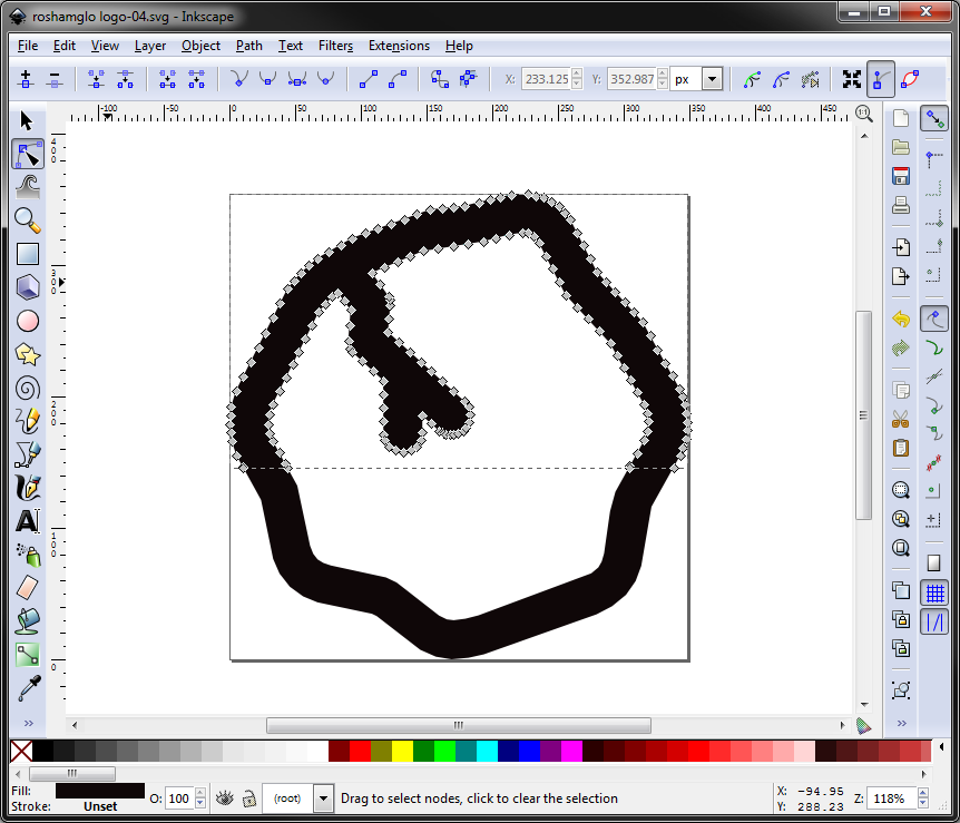
Select all nodes with the path editor tool (F2, Ctrl + a). Click Path > Break Apart (Shift + Ctrl + k).
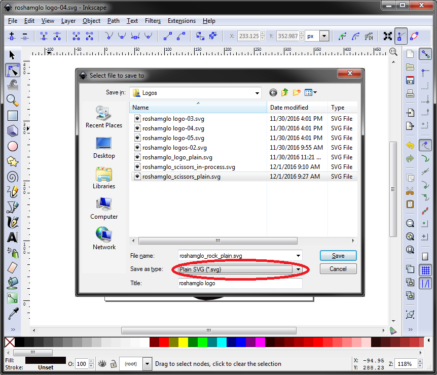
Click File > Save As, give your exported SVG file a name (make sure you include the .svg suffix!), and select Plain SVG (*.svg) from the Save as type: drop-down menu. Click Save.
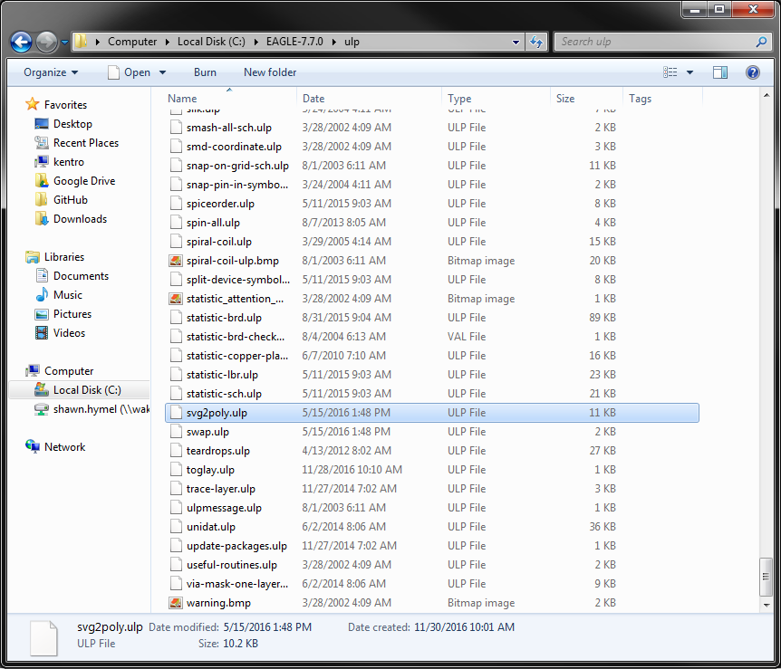
Download the Eagle-ULPs repository as ZIP. Unzip the directory, and copy the file svg2poly.ulp to the [EAGLE Directory]/ulp directory.
Start Eagle, and either create a new footprint or open your layout where you want to import the graphic.
If you want to put the image at a particular point, enter the command:
mark
and click where you want the center of the image to appear. Then, run the command (you can change the ratio to whatever you want to scale the image appropriately):
run svg2poly -ratio 0.001
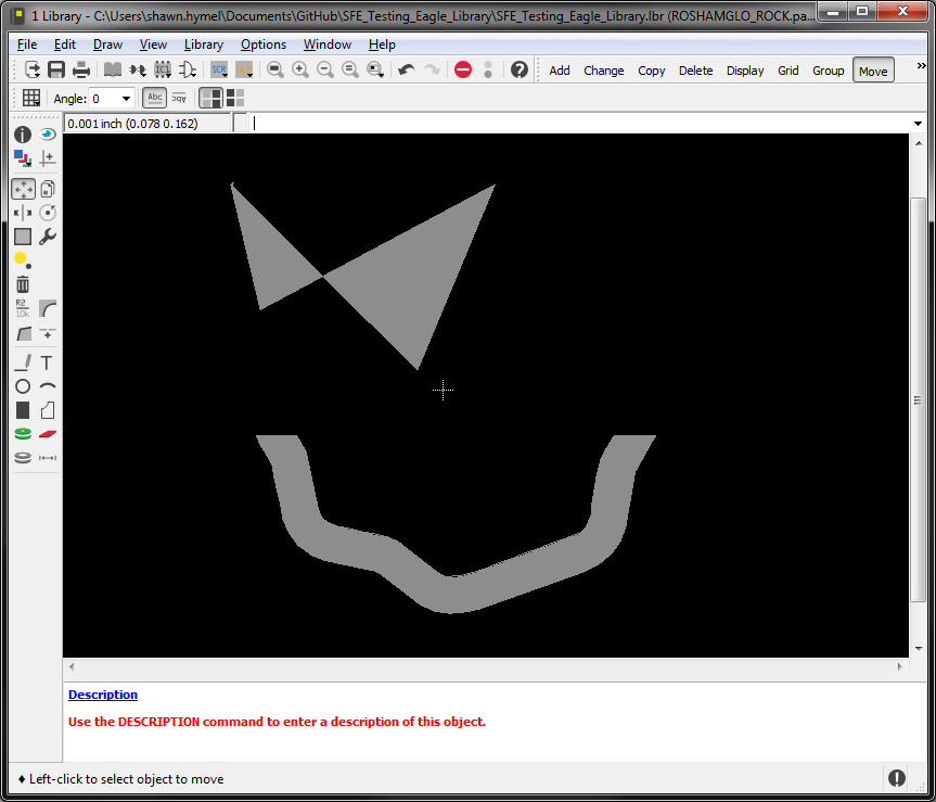
Select your plain SVG image, and it should be drawn on the tDocu layer. If the image does not show up properly, see the Troubleshooting section below.
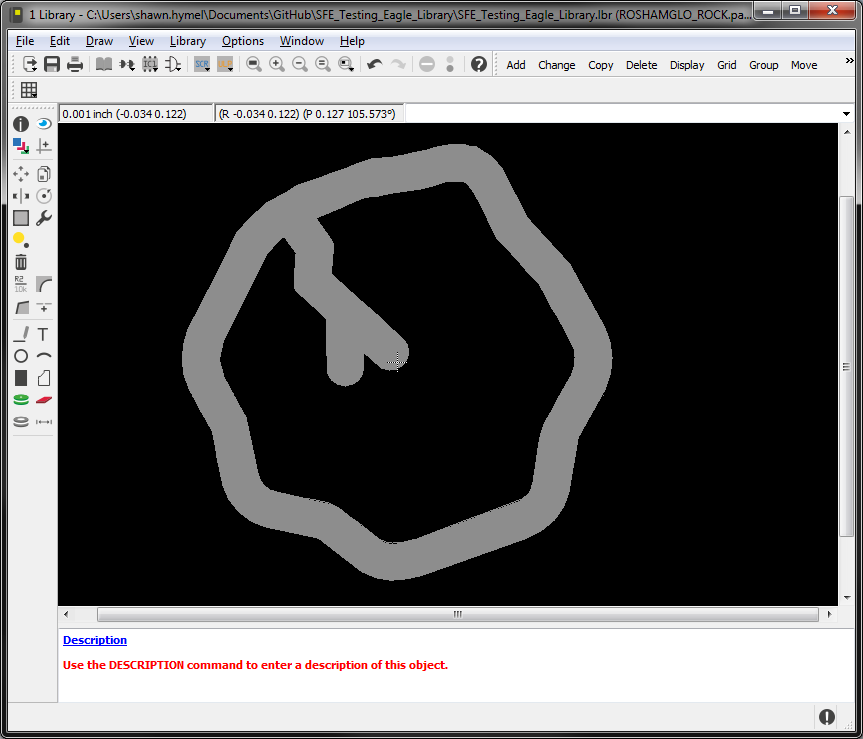
Since these are polygons, you can modify and tweak them as needed to meet your PCB needs. Also, you can change the layer to something else, like tPlace to make it appear in the top silk!
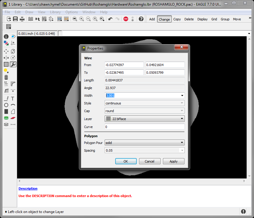
Right-click on each polygon section of your image in Eagle, select Properties, and change the Width to something larger than 0 (e.g. 0.001). Keep in mind that this will make your polygons slightly larger around the edges. Make sure you do this to every section in the image!
If your image does not import correctly (it often doesn't), there are a few tricks you can do to make it work.
First, figure out which sections of the image are not importing correctly, and divide them up more using the Cut Closed Loops method above. You can also try cutting closed loops in different ways. Make sure you select all nodes (F2, Ctrl + a) and Path > Break Apart (Shfit + Ctrl + k) before saving as a Plain SVG.
If certain sections are proving to be problematic, you can try deleting some of the nodes to see if that helps. If you delete nodes, you will need to select nodes in that section (F2) and Extensions > Modify Path > Flatten beziers. You then need to reselect all nodes in the image (F2, Ctrl + a) and Path > Break Apart (Shfit + Ctrl + k) before saving as a Plain SVG.
If all that fails, you can try manually drawing a new section in Inkscape. Don't forget to Add Nodes, Flatten Beziers, and Break Apart before saving the new image.

AutoCAD developed the Data Exchange Format (.DXF) to allow for sharing of files between AutoCAD and other programs. Lucky for us, newer versions of Eagle (7.7.0+) can also import DXF files. We can use that to add custom artwork to a layer.
If you don't already have it, download and install the latest version of Inkscape. You will need it for this method.
Draw, download, import, etc. your desired image. Make sure it is a single color (we'll use black) and saved as a vector graphic (e.g. SVG). In this example, we'll import an image made with Adobe Illustrator and saved as an SVG.
Click the select tool (F1), and select Edit > Select All in All Layers (Ctrl + Alt + a).
Click the button to lock the height/width ratio.
Change the units to mm, and change height to 100.
Go to File > Document Properties..., select Resize page to content... drop down, and click Resize page to drawing or selection.
Convert the object to a path and select nodes:
Add interpolated nodes and flatten beziers (we want straight lines for the polygon):
Any shapes that have a closed loop or a "hole," you'll need to cut them (Eagle doesn't know how to create a polygon with a hole in it).
Draw a shape, such as a rectangle, that divides the hole.
Hold Shift, and select both the rectangle and your image. Select Path > Division (Ctrl + /). Repeat this process for any closed loops in your image, such as donuts, outlines, and letters like 'o' and 'd'. You should end up with a number of paths that make up your image.
Select all nodes with the path editor tool (F2, Ctrl + a). Click Path > Break Apart (Shift + Ctrl + k).
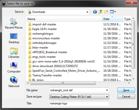
Click File > Save As, give your file a name (make sure to include the .dxf extension!), and select Desktop Cutting Plotter (R13) (*.dxf) from the Save as type: drop-down menu. Click Save.
Make sure use LWPOLYLINE type of output is selected, and click OK.

Start Eagle, and either create a new footprint or open your layout where you want to import the graphic.
Enter the command
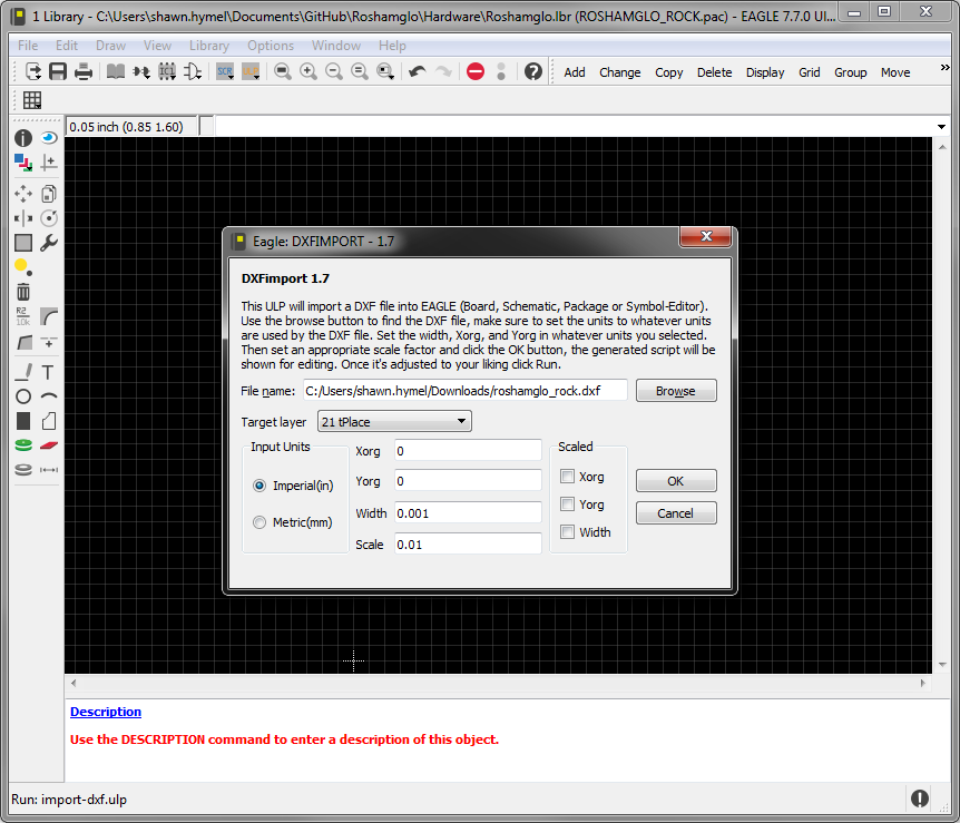
run import-dxf
Click Browse to select your DXF file. Select the target layer, and change the scale as desired.
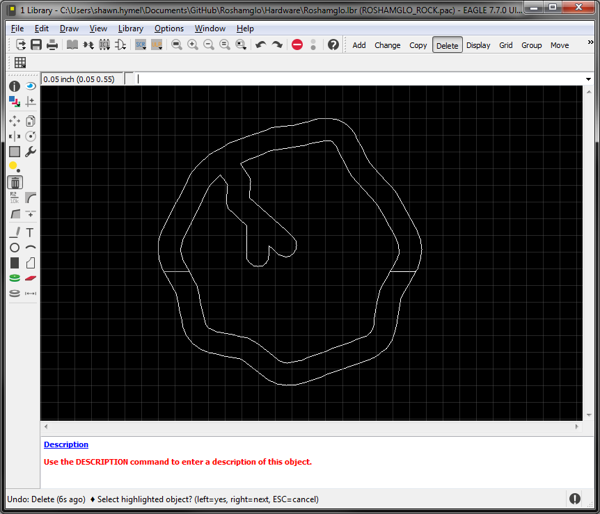
Click OK and Run on the pop-up window to import the image. Because the outline is made of lines, you can delete, move, and add lines as needed.
Importing a bitmap into Eagle is probably the easiest method, but the import process draws many rectangles on a separate layer, which can be difficult to modify. It is recommended that you use bitmaps as a template to draw lines or polygons in Eagle.
Use your favorite drawing program to create a monochrome (black and white) image.

Save the image as a Monochrome bitmap.

Start Eagle, and either create a new footprint or open your layout where you want to import the graphic.
Run the command:
run import-bmp
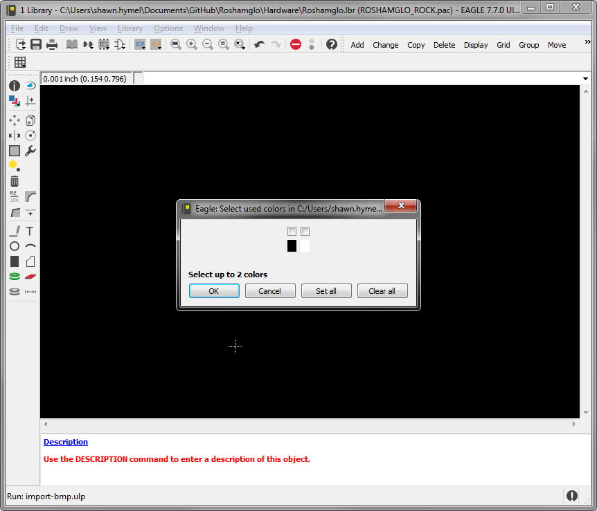
Read the pop-up window warning, and click OK. Select your bitmap file, and click Open. Select the black color to be imported, and click OK.
Scale your image as necessary, and select the desired units (I kept "mil" for this example).
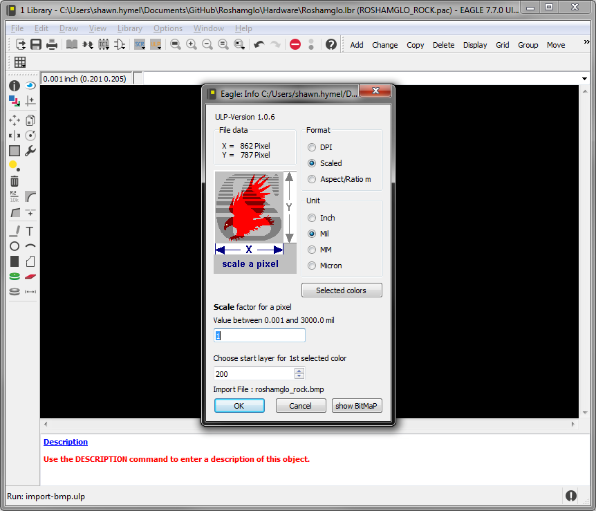
Click OK and Run script on the pop-up. Your image should be imported on the "200 200bmp" layer as a series of rectangles.
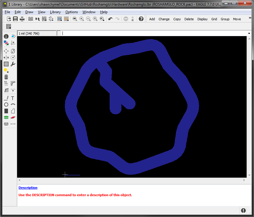
If you zoom in on the imported image, you'll see that it is actually made up of a series of rectangle shapes. These can slow down your computer and be a pain to work with if you need to make changes in Eagle, but it is a simple and effective way to get an image into Eagle.

Try playing with some of the layers in Eagle to make interesting effects in your artwork! For example, in the badger face from the Introduction, the face is on the tPlace (top silk) layer, but the eyes are on the Top (top copper) layer. When the boards are produced, the face is white, but the eyes come out silver, copper, or gold colored (depending on the finish used).

Check out these other resources to aid in graphic design on your PCBs.
Want to share your custom artwork with others? Check out these tutorials on how to contribute to and make your own public GitHub repositories. What more advanced Eagle tips and Tricks? Learn how to take your design to the next levels with these other great SparkFun Eagle tutorials.
Or check out these blog posts for ideas when using negative silkscreen and custom utilities.
learn.sparkfun.com | CC BY-SA 3.0 | SparkFun Electronics | Niwot, Colorado