How to Install and Setup EAGLE
 jimblom
Opening a Project and Explore
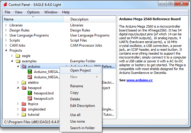
EAGLE is packaged with a handful of nifty example PCB designs. Open one up by expanding the "Projects" tree. From there, under the "examples" folder open up the "arduino" project by double-clicking the red folder (or right-clicking and selecting "Open project"). Note that, in this view, project folders are red and regular folders are the standard yellow.
Opening the project should cause two more EAGLE windows to spawn: the board and schematic editors. These are the yin and the yang of EAGLE. They should be used together to create the finished product that is a functional PCB design.
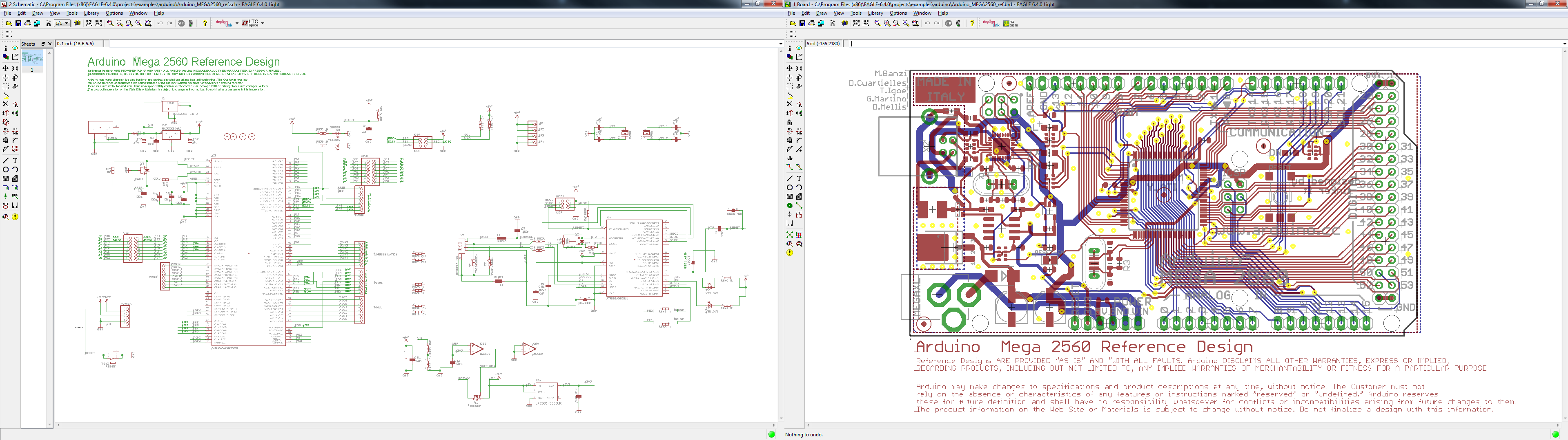
The schematic editor (on the left above) is a collection of red circuit symbols which are interconnected with green nets (or wires). A project's schematic is like the comments in a program's code. It helps tell the story of what the board design actually does, but it doesn't have much influence on the end product. Parts in a schematic aren't precisely measured, they're laid out and connected in a way that's easy to read, to help you and others understand what's going on with the board design.
The board editor is where the real magic happens. Here colorful layers overlap and intersect to create a precisely measured PCB design. Two copper layers -- red on top, blue on the bottom -- are strategically routed to make sure different signals don't intersect and short out. Yellow circles (on this design, but they're more often green) called "vias" pass a signal from one side to the other. Bigger vias allow for through-hole parts to be inserted and soldered to the board. Other, currently hidden, layers expose copper so components can be soldered to it.
Keep Both Windows Open!
Both of these windows work hand-in-hand. Any changes made to the schematic are automatically reflected in the board editor. Whenever you're modifying a design it's important to keep both windows open at all times.
If, for instance, you closed the board window of a design, but continued to modify a schematic. The changes you made to the schematic wouldn't be reflected in the board design. This is bad. The schematic and board design should always be consistent. It's really painful to backtrack any changes in an effort to reattain consistency. Always keep both windows open!
There are a few ways to tell if you don't have consistency between windows. First, there's a "dot" in the lower-right hand corner of both windows. If the dot is green, everything is groovy. If the dot is magenta, a window's probably closed that shouldn't be. Second, and more obvious, if you close either of the two windows a big, huge warning should pop up in the other:
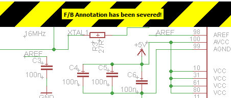
If you see that warning STOP doing anything, and get the other window back open. The easy way to get either a board or schematic window back open is by clicking the "Switch to board/schematic" icon --  /
/  (also found under the "File" menu).
Navigating the View
This is a subject that's usually glazed over, but it's important to know how to navigate around both of these windows.
To move around within an editor window, a mouse with a scroll wheel comes in very handy. You can zoom in and out by rotating the wheel forward and backward. Pressing the wheel down, and moving the mouse allows you to drag the screen around.
If you're stuck without a three-button mouse, you'll have to resort to the view options to move around the editor views. All of these tools are located near the middle of the top toolbar, or under the "View" menu. The zoom in --  -- and zoom out --
  -- tools are obviously handy. So is the "Zoom select" tool --
  -- which alters the view to your selection. But really, if you're serious about using EAGLE...get a mouse!