How Chip-On-Boards are Made
 Nate
Nate 
COB Manufacturing
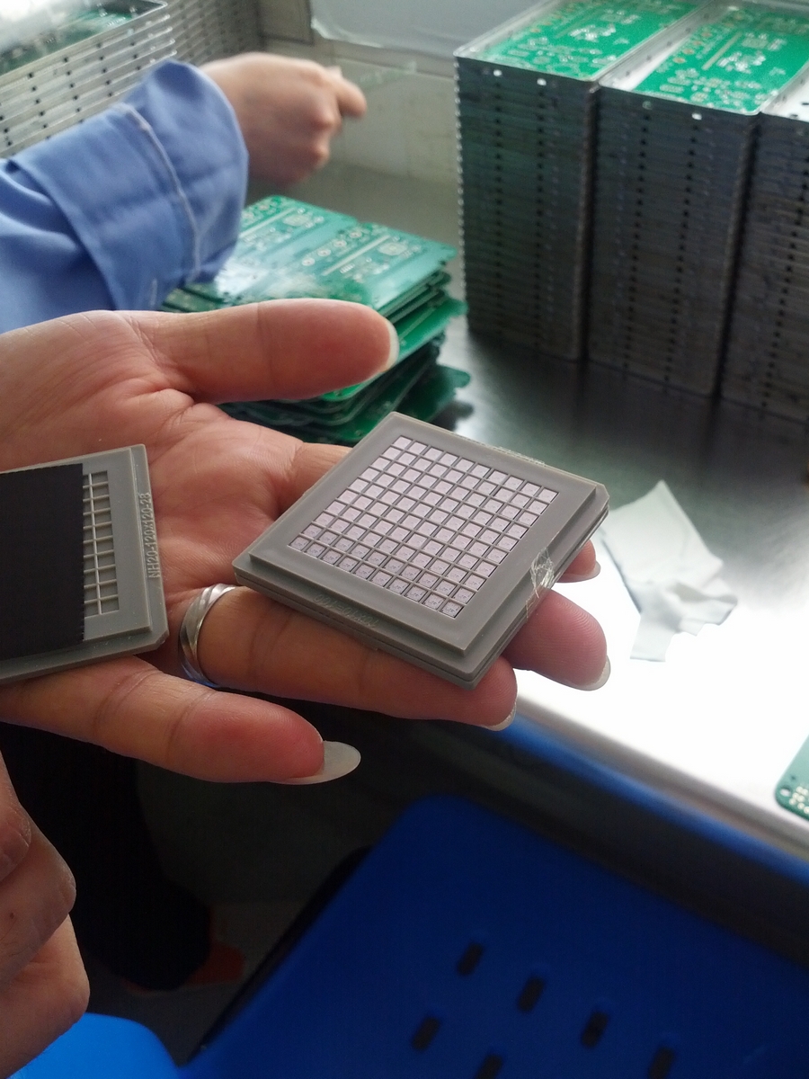
Shown above is a tray of controller silicon dies that serve as the brain of the multimeter. These ICs are made by a different company and are ordered with features that are desired in the overall feature set of the DMM. While I shouldn't have been surprised, it was interesting to think about the fact that there are companies setup to create nothing but DMM controller ICs. What I now understand is that few multimeter companies own the entire tool-chain to create a DMM. Instead, there are companies that specialize in small cottage industries: manufacturing the DMM displays, the batteries, the control ICs, and assembly of the parts into a final DMM.
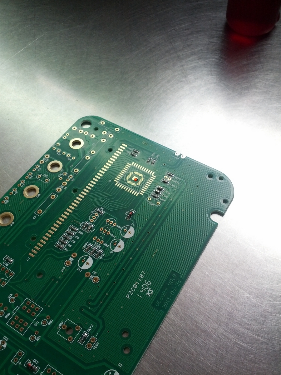
Very similar to how LEDs are made, the first step is to glue the silicon die to the PCB. I'm not entirely sure if the adhesive is conductive or not, but, judging by the exposed pad, it probably is.
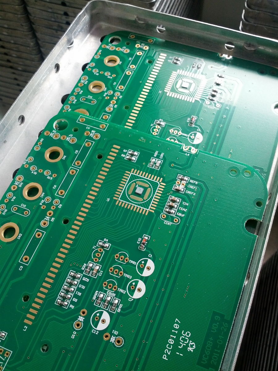
With a pair of tweezers the dies are placed by hand(!). The adhesive sets within 5 minutes. This was another moment that caught me off guard: I assumed COB required a clean room with precision tools and ultra-accurate placement. It turns out, just like SMD soldering in a hot plate; you can have a lot of variance and still have a fully functional board.
ReplaceMeOpen
ReplaceMeClose
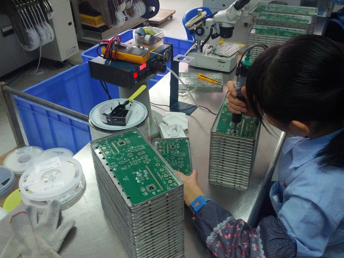
The PCB is then inserted into an amazing automated wire bonding machine that bonds a very thin wire from the IC to the PCB. You can see the operator has to tell the visual recognition system a few alignment spots once in awhile, but in general, the machine quickly solders all the connections.
From one of our readers manton:
It would be unlikely that the wire bonding process is done by soldering the wires. Usually this is done using thermosonic bonding, which uses a combination of heat, pressure, and ultrasonic vibrations to bond the wires.
Very good point! Thanks Manton. I thought it was soldering because that's what I know but this is thermosonic bonding.
ReplaceMeOpen
ReplaceMeClose
In the video above, you can see that the machine requires some operator input to bond the last connection, completes it, and the board is done. You also get a sense for how rough the boards can be handled without damaging the connections. I expected the hair like connections to be quite fragile, but, instead, the boards can be handled regularly. This is very similar to how liquid solder paste holds SMD components solidly in place before they enter the reflow oven.
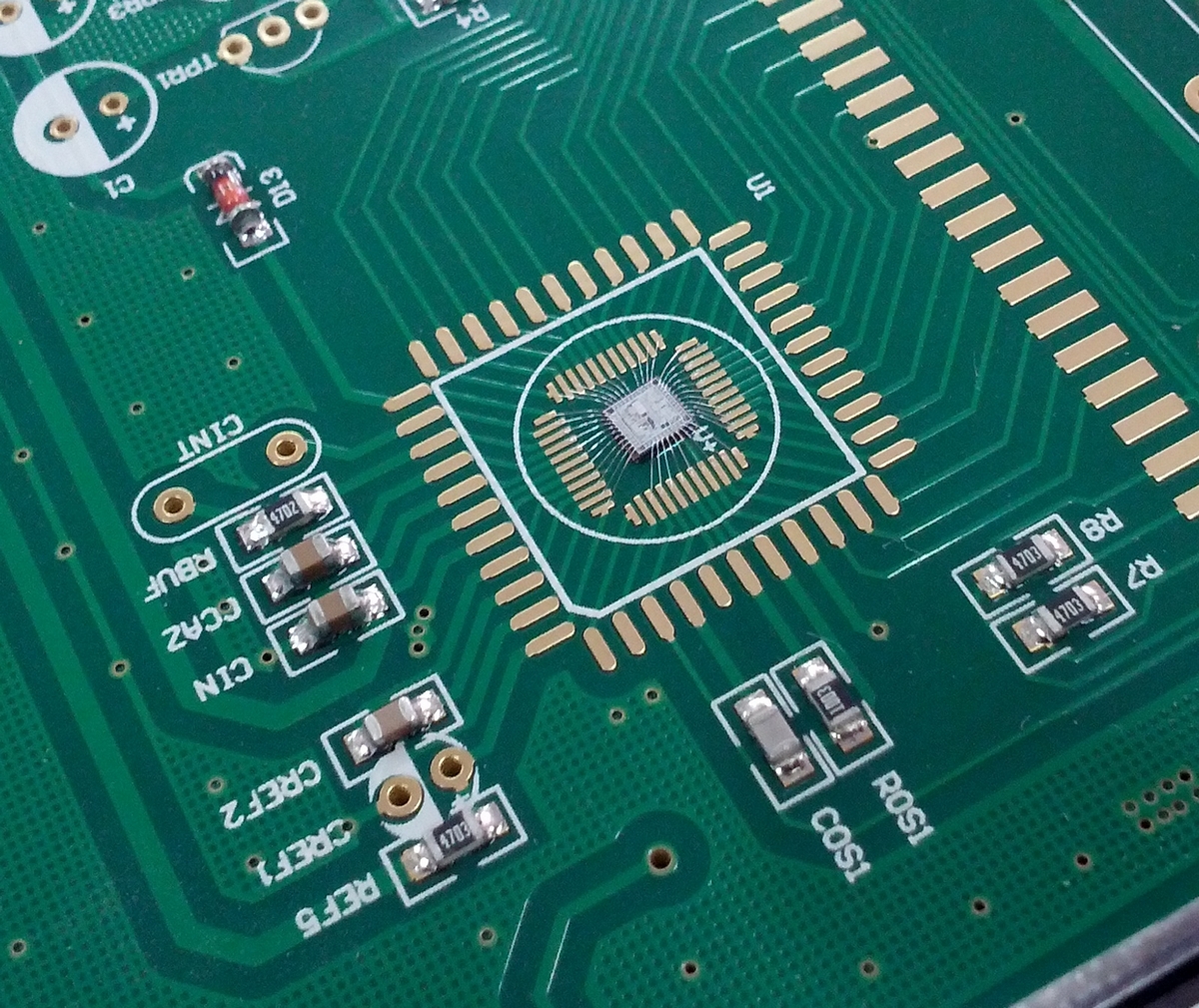
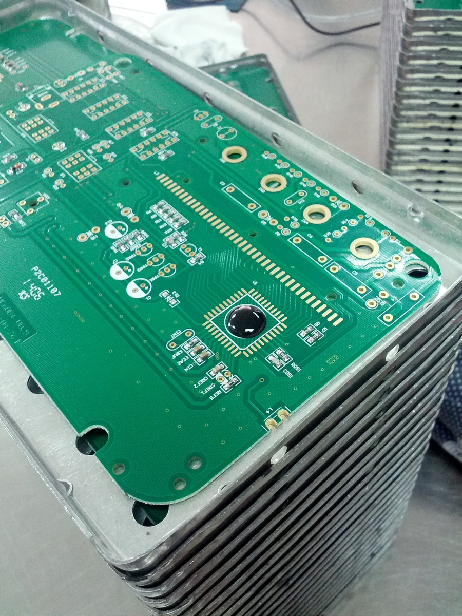
Forty one connections later, and the die is all connected up. As you can see, the small theta rotation of the IC doesn't make much of a difference.
The next step is to squirt a small dab of potting compound over the entire structure. This material electrically and physically protects the die and wire bonds from damage.
The viscosity of the compound must be tightly controlled to prevent the hairs from bending over and connecting with neighboring wires.
The liquid compound is then cured in an oven for four hours. Once complete the boards are tested and continue down the process of becoming a multimeter.
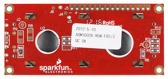
Now, whenever you see those black blobs on an electronic device, such as the ones on our 16x2 basic LCD, you'll know how they are made!