Hookup Guide for the SparkFun RedBoard Artemis ATP
 Nate, Ell C
Hardware Overview
If you've ever used an Arduino Mega before you should be pretty familiar with the various female headers and the barrel jack power. In this tutorial we'll be covering the unique aspects of the RedBoard Artemis ATP.
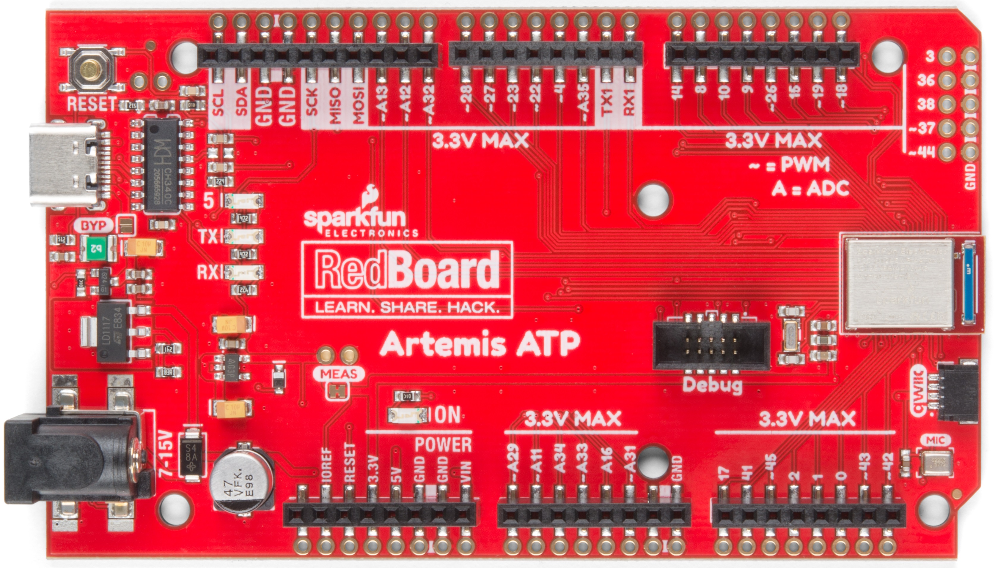
The ADC on the Artemis is 0-2V. Exposing an ADC pin to 3.3V will not harm the device but the ADC will saturate returning 16,383 (14-bit) for voltages greater than 2V.
GPIO
Remember our "All the Pins!" nickname? Well, we meant it. On the RedBoard Artemis ATP, not only have we broken out all the major pins with female headers, we've added a secondary rail of plated through-holes alongside them to give you the choice of either plug and play or soldering directly to the board.
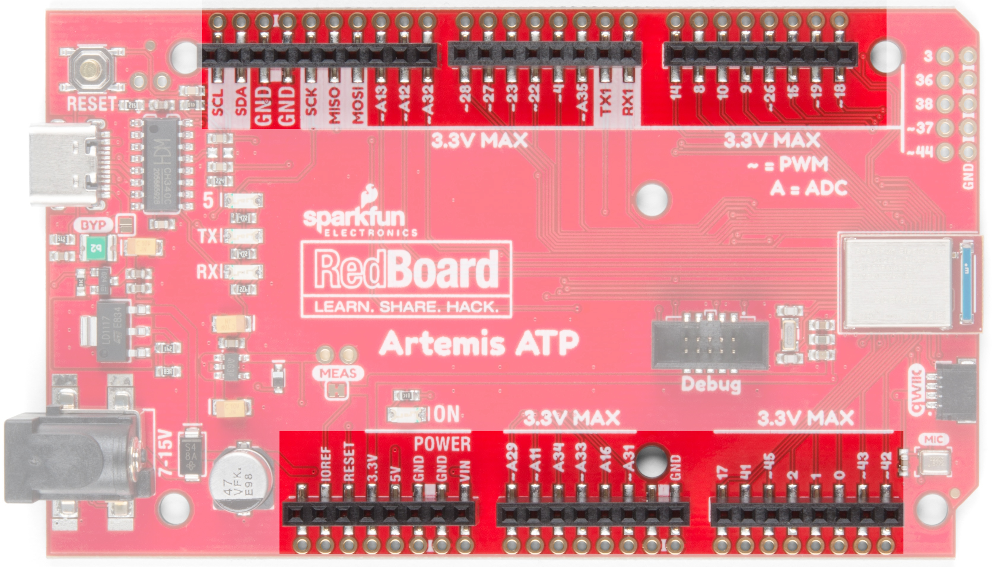
On the side of the board, instead of doubling the pin availability, we've added a rail of ground pins for ease of use.

Serial and JTAG Programming
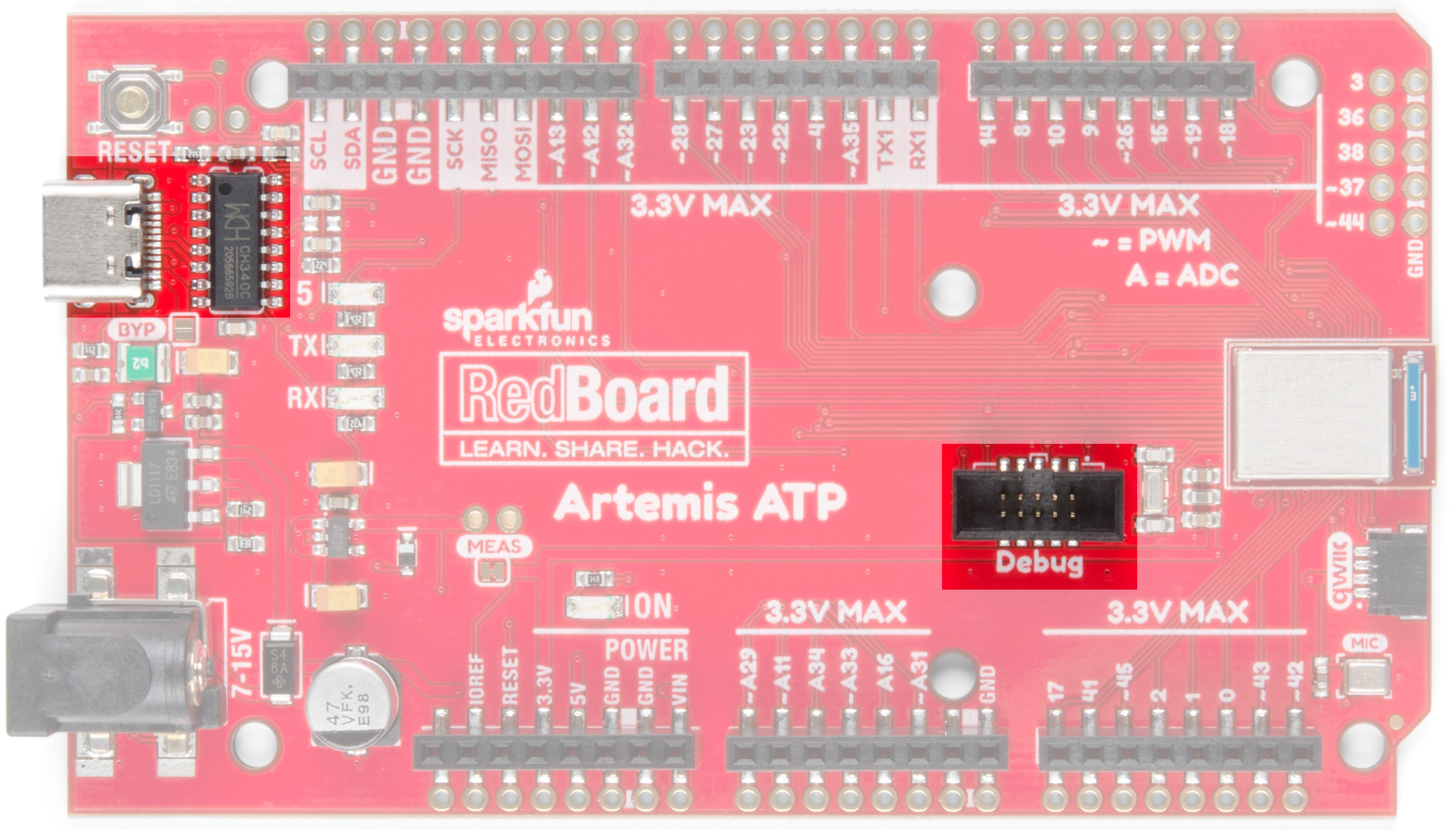
The RedBoard Artemis ATP has two methods for programming. The most common is the USB C connector that operates as a USB to serial bridge. By simply pressing 'Upload' in the Arduino IDE or 'make bootload' from the SDK the firmware on Artemis is updated.
We use the CH340C on the RedBoard Artemis ATP. The driver should automatically install on most operating systems. However, there is a wide range of operating systems out there. You may need to install drivers the first time you connect the chip to your computer's USB port or when there are operating system updates. For more information, check out our How to Install CH340 Drivers Tutorial.
How to Install CH340 Drivers
The second method is JTAG programming. We've populated the JTAG footprint for more advanced users who need breakpoint level debugging. We recommend checking out our JTAG section for the compatible JTAG programmer and debugger.
Mic and RTC
The Artemis excels at low power voice recognition. To enable this we've included a PDM MEMS microphone on the board. Additionally, the Artemis module can operate an RTC given an external 32kHz crystal so we've included that was well.

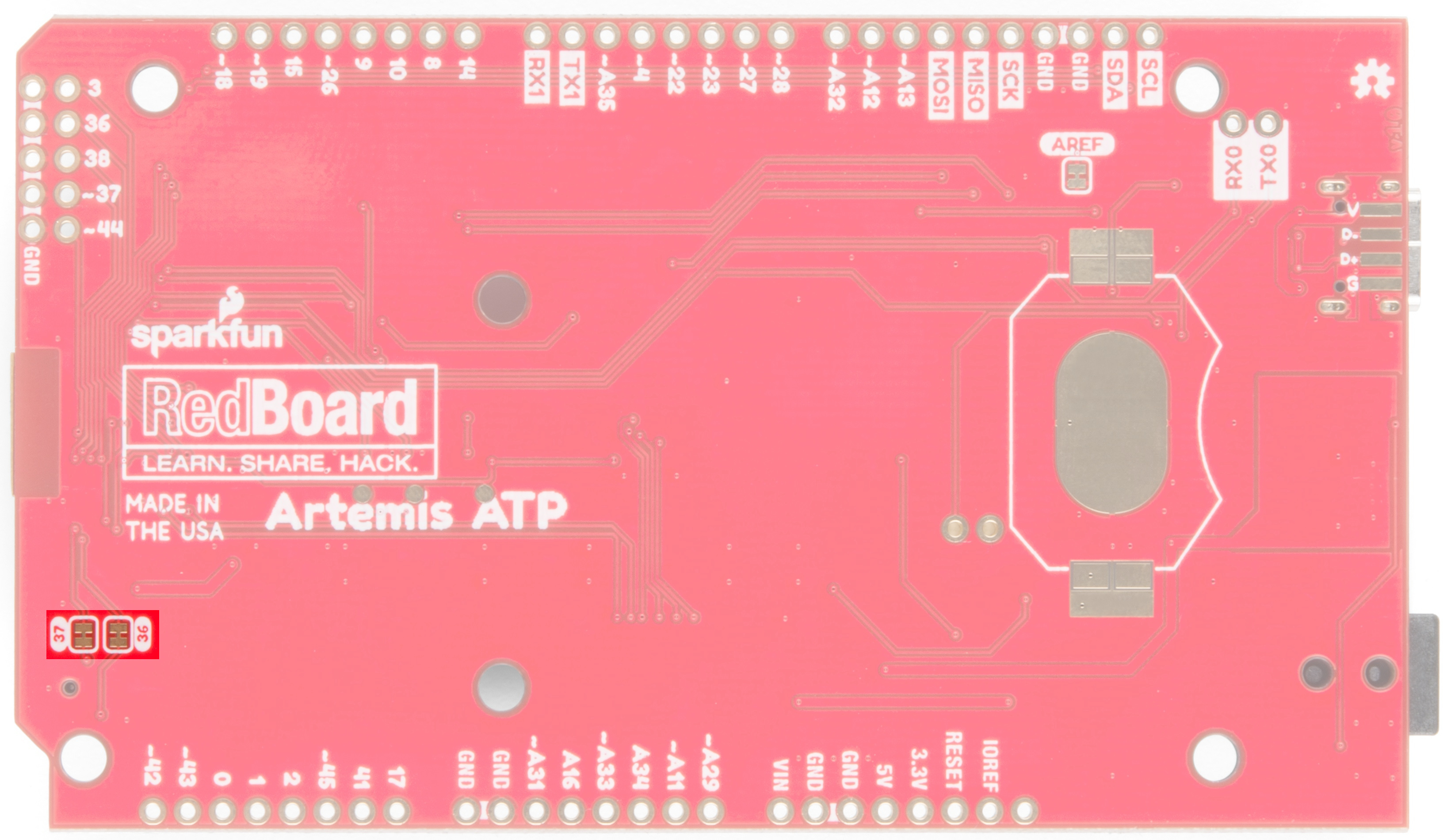
Pins 36 and 37 are connected to the onboard PDM MEMS microphone and are broken out on the upper right side of the ATP board. You can hookup a second PDM microphone to pins 36/37 or you can load PDM firmware onto the Artemis module and watch PDM traffic from the microphone(s). Notice the ground pins next to pins 36 and 37!
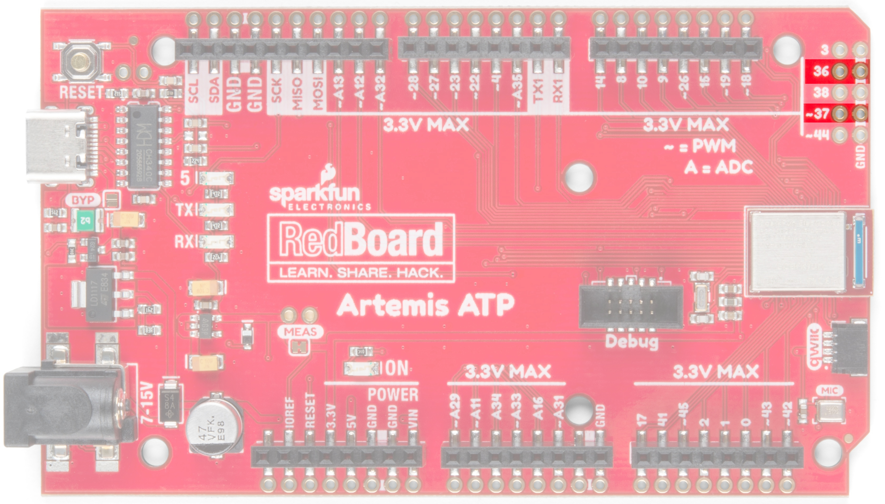
If you have no plans to use the on-board microphones, pins 36 and 37 can be used as GPIO by cutting the jumpers on the back of the board.
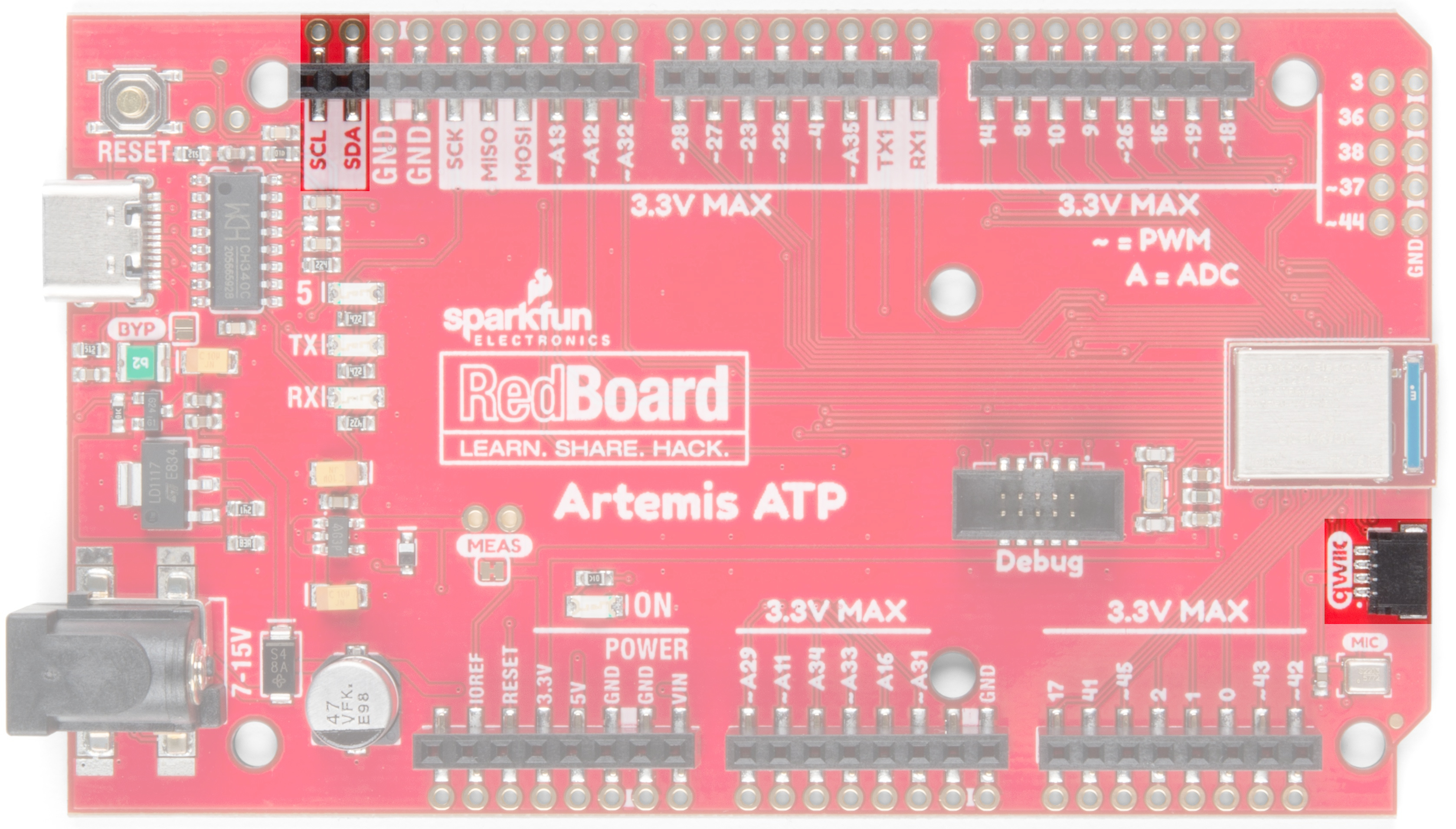
Qwiic and I2C
The I2C pins on the Artemis are labeled SDA and SCL. They are controlled in the Arduino IDE using Wire.begin(), Wire.read(), etc. The same SDA/SCL pins are connected to the Qwiic connector so you can use SparkFun's Qwiic ecosystem (there's over 50 boards and more every week!).
Serial0, AREF, and USB Pads
On the rear of the RedBoard ATP are some advanced features. Normally, an AREF pin is located between to the SDA and GND pins. The Artemis module has no equivalent pin so we've converted that pin to GND. If you have a shield that utilizes the AREF pin or just want to free it, you can cut the AREF jumper and the labeled 'GND' located between SDA and GND will be left disconnected.
On Artemis, TX0/RX0 are used for bootloading new code and Serial.println() statements to the computer's terminal window. The CH340C takes care of the serial to USB conversion. However, if you need access to these pins, they are available. TX0/RX0 can be used as GPIO as well as special functions, but for most applications these pins are left as Serial for bootloading.
For users who are embedding the RedBoard Artemis ATP into an enclosure, the USB pads are exposed so that an external USB connector can be located at the edge of the enclosure and wired back to the USB pads.

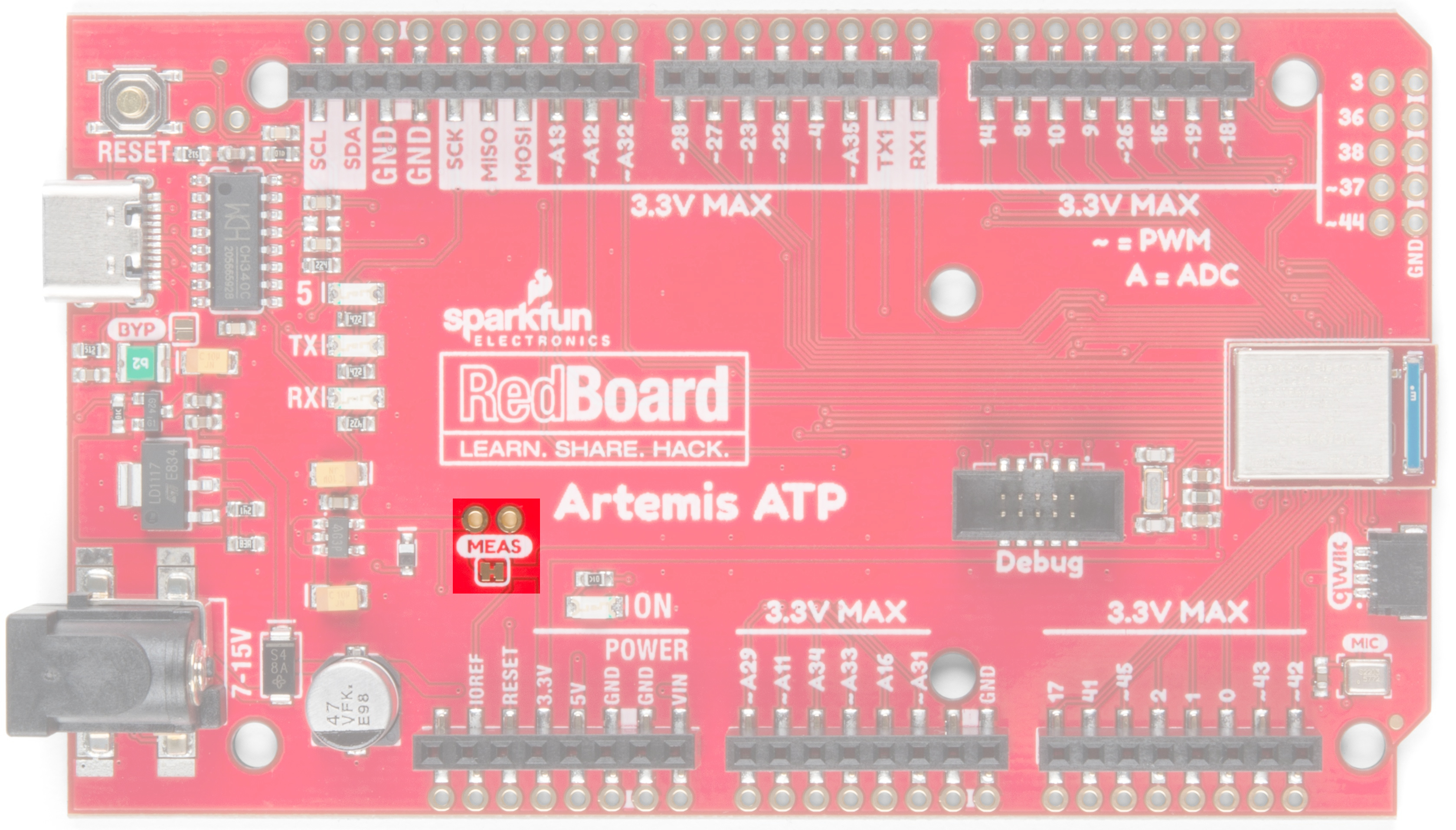
Current Measurement Jumper
The Artemis can run as low as 6μA/MHz, meaning the module can run at 48MHz at less than half a milliamp. To enable measurements and to isolate the power hungry devices (such as the LM317 voltage regulator) we've added a NC (normally closed) jumper. By cutting the jumper the VDD trace to the module is interrupted. Soldering in a male jumper or wires into the accompanying holes will give you the ability to insert a current meter and precisely monitor how much current your application is consuming.
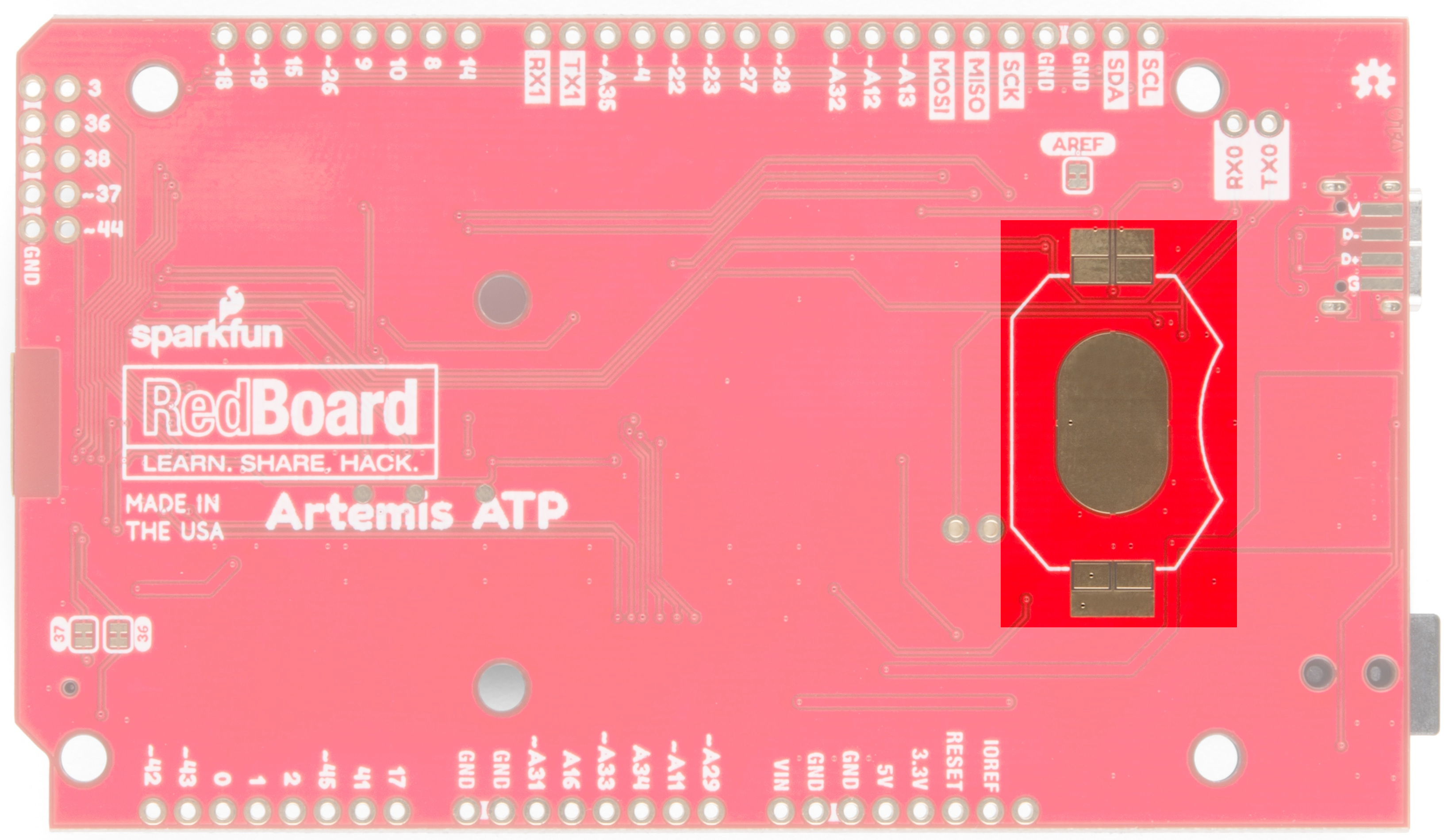
For the vast majority of projects a wall adapter or USB power can be used. But when properly isolated the Artemis can run on a coincell battery for weeks! So we've designed in a 20mm SMD coin cell footprint so that users can experiment with powering the Artemis from a standard CR2032. You can pickup the compatible coincell holder here.Be careful when soldering, the coincell silk screen pads are a bit larger than usual.
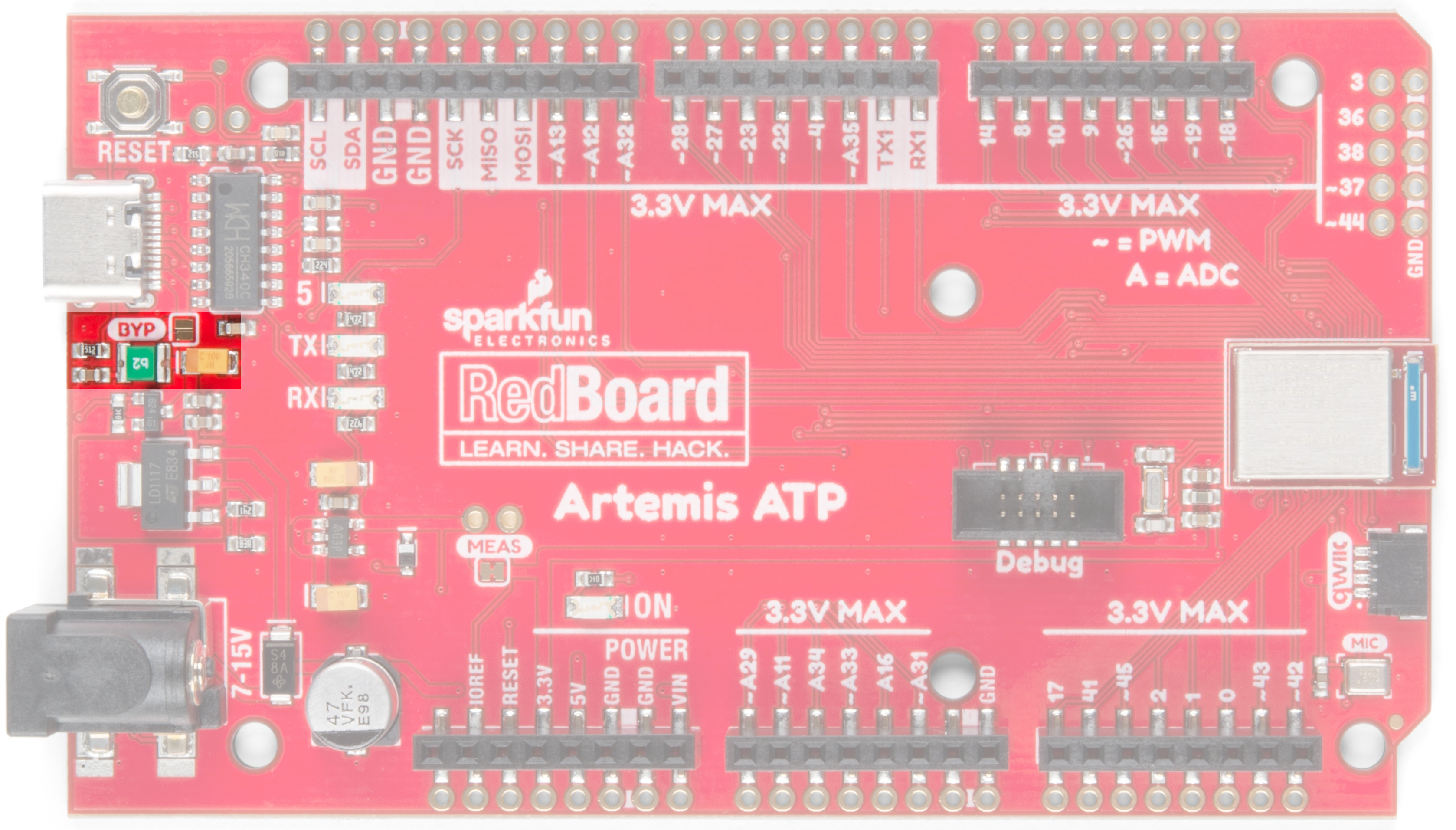
Bypass Jumper
USB C is wonderful. It's reversible and can source up to 2 amps at 5 volts without any power delivery (PD) negotiation. We've included a 2A resettable fuse (often called a PTC) on the Artemis as a safety feature in case your project decides to consume inordinate amounts of power (And possibly begins to spark and set fire. That was fun wasn't it? Get it? SparkFun?). In the event the RedBoard begins to pull more than 2 amps from the USB source, the resettable fuse will automatically trigger and disconnect the board from the computer or power supply. This should protect your power source and the traces on your RedBoard.
However, there are plenty of legitimate projects that need more than 2A. We've designed the power traces to withstand up to 2A with a 10C rise in temperature. If your power supply can provide adequate power, and you know what you are doing, you can close the BYP jumper, thus circumventing the resettable fuse.
I/O Masters
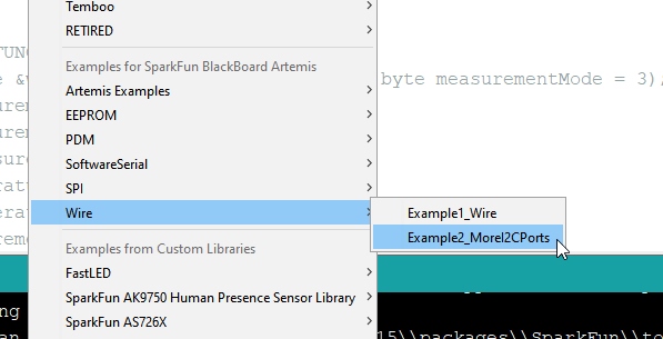
You can have up to 6 I2C or SPI masters with the RedBoard Artemis ATP, and these pins are distributed across the board. Be sure to check out the good examples built into the Artemis Arduino core showing how to easily enable additional ports.
In addition we've listed each of the masters below with their associated pins. Check out the Apollo3 PinMap for more information.
| Master | SCK/SCL | MISO/SDA | MOSI |
|---|---|---|---|
| M0 | 5 | 6 | 7 |
| M1 | 8 | 9 | 10 |
| M2 | 27 | 25 | 28 |
| M3 | 42 | 43 | 38 |
| M4 | 39 | 40 | 44 |
| M5 | 48 | 49 | 47 |