$23.78
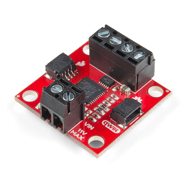
The Qwiic Motor Driver takes all the great features of the Serial Controlled Motor Driver and mini-sizes them, adding Qwiic ports for plug and play functionality. Boasting the same PSOC and 2-channel motor ports, the QWIIC Motor Driver is designed to communicate over I2C, but UART is also available.
To follow along with this tutorial, you will need the following materials. You may not need everything though depending on what you have. Add it to your cart, read through the guide, and adjust the cart as necessary.
If you aren’t familiar with the following concepts, we recommend you read over these tutorials before continuing.
Let's look at some of the various features of the hardware.
Features:
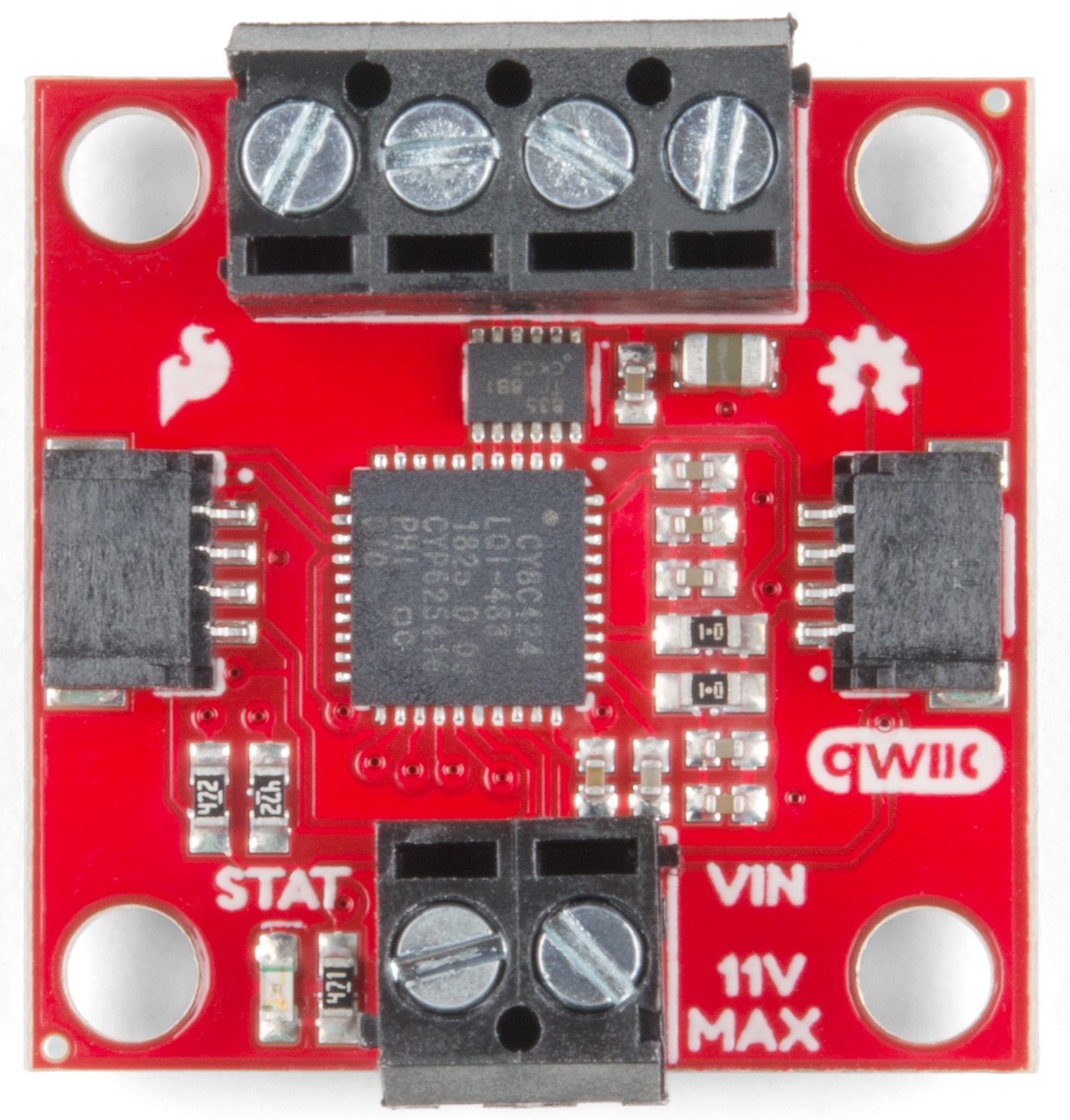
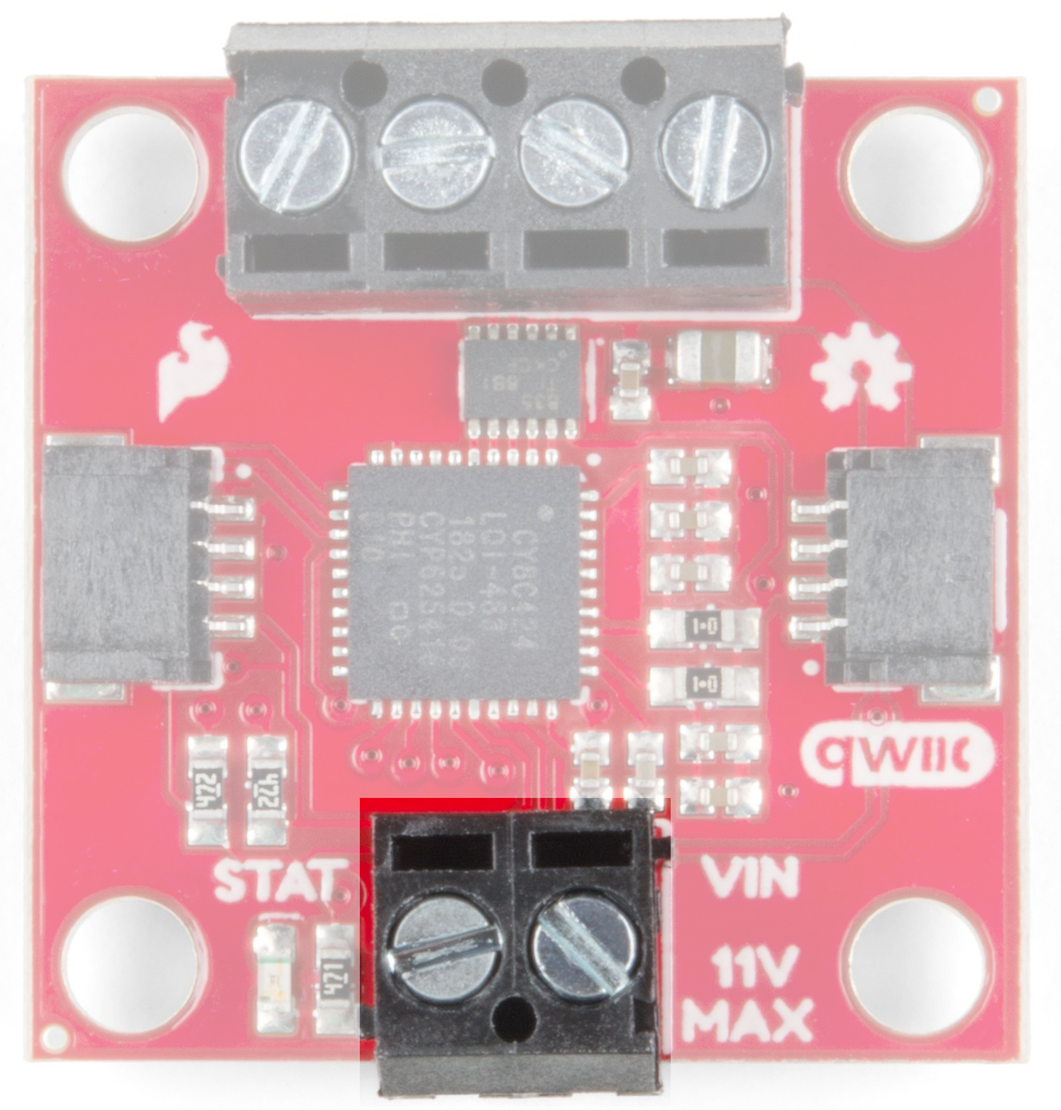
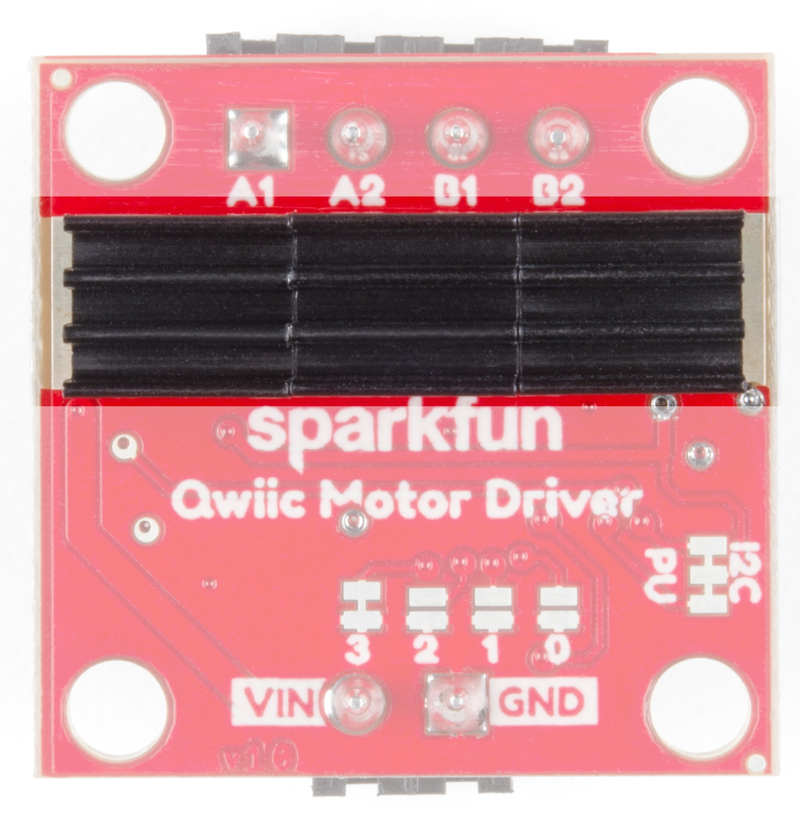
There are two separate power circuits on this board . Power for the motors is supplied through the VIN Connectors - you can provide anywhere from 3.3V to 11V to the "MAX 11V" and "GND" connections. Power for the PSOC and logic circuits is provided by the 3.3V inputs on the Qwiic connectors. Both are needed for proper functioning.
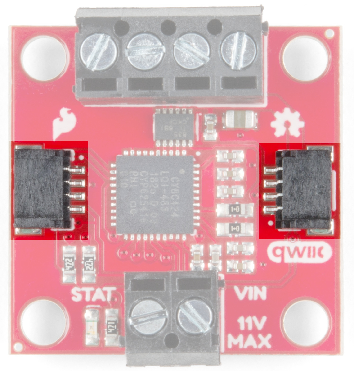
There are two Qwiic connectors on the board such that you can provide power or daisy-chain the boards should you choose to do so. If you're unfamiliar with our Qwiic system, head on over to our Qwiic page to see the advantages!
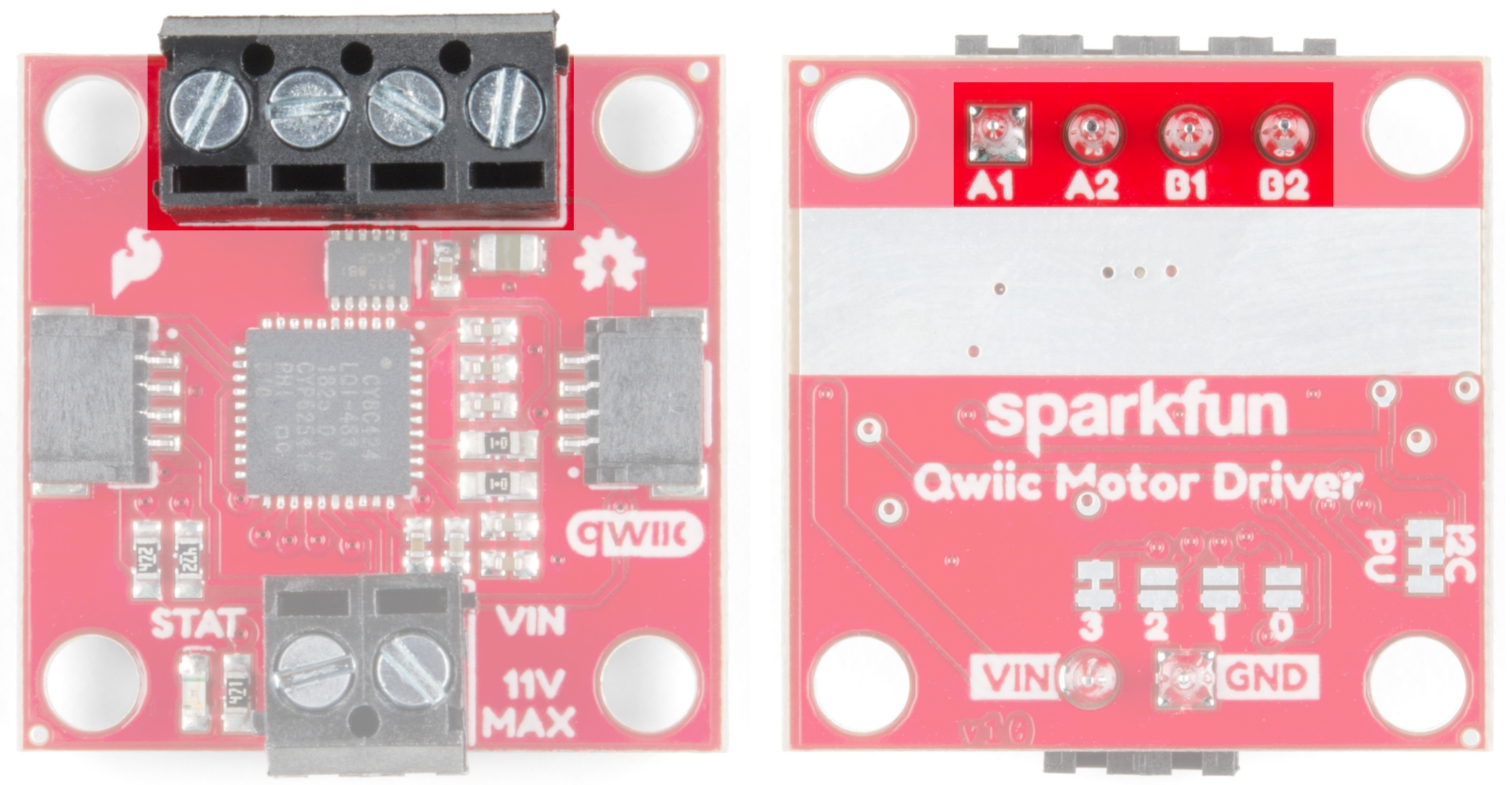
The screw pin terminals at the top of the board allow for two motor connections. They are labeled on the backside of the board.
| Function / Connection | ||||||
|---|---|---|---|---|---|---|
| Group | Name | Direction | Description | UART | I2C | |
| Motor Port | A1 | O | Winding of first addressable location | Motor A winding | ||
| A2 | O | Winding of first addressable location | Motor A winding | |||
| B1 | O | Winding of second addressable location | Motor B winding | |||
| B2 | O | Winding of second addressable location | Motor B winding | |||
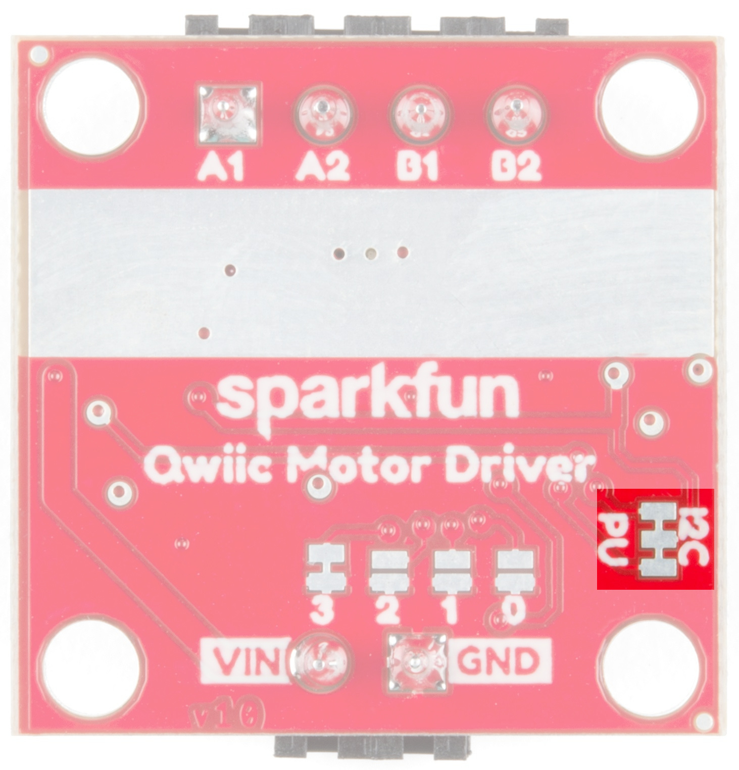
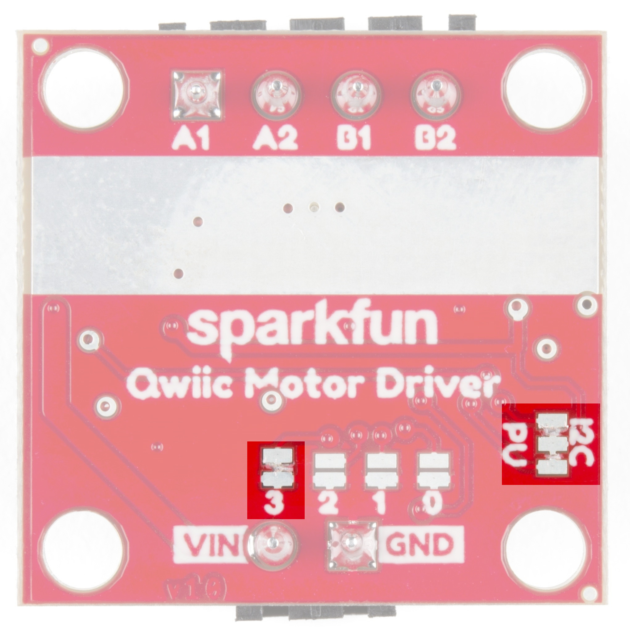
There are 2 sets of jumpers to configure on this board. There are pull-up enables for I2C and 4 config bits that select operational mode.
| Name | Description | Usage |
|---|---|---|
| I2C Jumpers | I2C pull-up enable | Opening these disables theI2C pull-up resistors used for I2C communication. If multiple I2C devices are being used, these pull-ups should be disabled on all but one device. If UART is being used, the pull-up resistors should be disabled. |
| Address Jumpers | Serial and function selection | The config bits are 4 bits that form a configuration nybble. A closed jumper is a '1' and an open jumper is a '0'. See config table for more information. |
The configuration is set by encoding a number into the 4 config bits on the bottom of the board. Close a jumper to indicate a 1, or leave it open to indicate a 0.
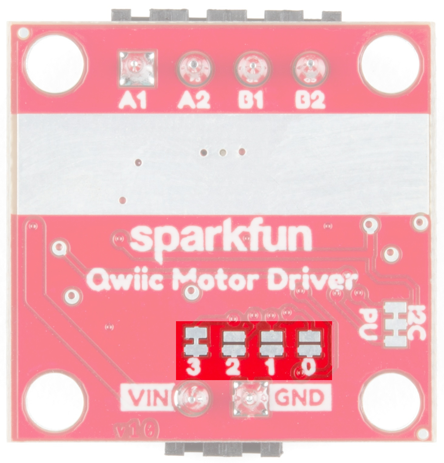
Use this table to see what the user port, address, and expansion port will become in each configuration:
| Pattern | Mode | User Port | User Address | Expansion Port |
|---|---|---|---|---|
| 0000 | UART at 9600 | UART | N/A | Master |
| 0011 | I2C | I2C | 0x58 | Master |
| 0100 | I2C | I2C | 0x59 | Master |
| 0101 | I2C | I2C | 0x5A | Master |
| 0110 | I2C | I2C | 0x5B | Master |
| 0111 | I2C | I2C | 0x5C | Master |
| 1000 | I2C | I2C | 0x5D | Master |
| 1001 | I2C | I2C | 0x5E | Master |
| 1010 | I2C | I2C | 0x5F | Master |
| 1011 | I2C | I2C | 0x60 | Master |
| 1100 | I2C | I2C | 0x61 | Master |
| 1101 | UART at 57600 | UART | N/A | Master |
| 1110 | UART at 115200 | UART | N/A | Master |
| 1111 | N/A | Reserved | N/A | N/A |
The Qwiic Motor Driver is designed to operate small robot drive motors without a heatsink; we were able to run up to about 1.1A continuous current without going above 100°C. If you find that you need a heatsink, you can use our Theragrip Thermal Tape to attach three Small Heat Sinks across the thermal conduction area on the back of the board.
If you need more information on how to determine whether or not you need a heat sink, kick on over to the Serial Controlled Motor Driver Hookup Guide and scroll down to Typical Application Motors and Heat Sinking.
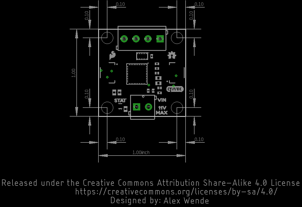
All measurements are in inches. The Qwiic Motor Driver PCB measures 1x1 inch, with slight overhangs for the power and motor screw terminals.
If you haven't used the Arduino IDE before, head on over to our Installing the Arduino IDE tutorial to get set up:
The Qwiic Motor Driver uses the same Arduino Library as the Serial Controlled Motor Driver (hereafter referred to as SCMD). To get the Arduino library, either download and install it from Github or use the Arduino Library Manager.
Download the Github repository
Visit the GitHub repository to download the most recent version of the library, or click the link below:
Use the library manager or install in the Arduino IDE
In the Library Manager, search for Serial Controlled Motor Driver. For help installing the library, check out our How To Install An Arduino Library tutorial.
Let's start by hooking up some motors and making sure they're running. Since the Qwiic Motor Driver uses the same PSOC as the Serial Controlled Motor Driver, the same examples will work with minor modifications.
The following test is essentially the TwoMotorRobot.ino example from the SCMD library, but with a few minor changes to account for the defaults of the Qwiic Motor Driver.
Copy and paste the following code into your Arduino browser and upload.
language:c
//This example drives a robot in left and right arcs, driving in an overall wiggly course.
//  It demonstrates the variable control abilities. When used with a RedBot chassis,
//  each turn is about 90 degrees per drive.
//
//  Pin 8 can be grounded to disable motor movement, for debugging.

#include <Arduino.h>
#include <stdint.h>
#include "SCMD.h"
#include "SCMD_config.h" //Contains #defines for common SCMD register names and values
#include "Wire.h"

SCMD myMotorDriver; //This creates the main object of one motor driver and connected peripherals.

void setup()
{
  pinMode(8, INPUT_PULLUP); //Use to halt motor movement (ground)

  Serial.begin(9600);
  Serial.println("Starting sketch.");

  //***** Configure the Motor Driver's Settings *****//
  //  .commInter face is I2C_MODE
  myMotorDriver.settings.commInterface = I2C_MODE;

  //  set address if I2C configuration selected with the config jumpers
  myMotorDriver.settings.I2CAddress = 0x5D; //config pattern is "1000" (default) on board for address 0x5D

  //  set chip select if SPI selected with the config jumpers
  myMotorDriver.settings.chipSelectPin = 10;

  //*****initialize the driver get wait for idle*****//
  while ( myMotorDriver.begin() != 0xA9 ) //Wait until a valid ID word is returned
  {
    Serial.println( "ID mismatch, trying again" );
    delay(500);
  }
  Serial.println( "ID matches 0xA9" );

  //  Check to make sure the driver is done looking for peripherals before beginning
  Serial.print("Waiting for enumeration...");
  while ( myMotorDriver.ready() == false );
  Serial.println("Done.");
  Serial.println();

  //*****Set application settings and enable driver*****//

  //Uncomment code for motor 0 inversion
  //while( myMotorDriver.busy() );
  //myMotorDriver.inversionMode(0, 1); //invert motor 0

  //Uncomment code for motor 1 inversion
  while ( myMotorDriver.busy() ); //Waits until the SCMD is available.
  myMotorDriver.inversionMode(1, 1); //invert motor 1

  while ( myMotorDriver.busy() );
  myMotorDriver.enable(); //Enables the output driver hardware

}

#define LEFT_MOTOR 0
#define RIGHT_MOTOR 1
void loop()
{
  //pass setDrive() a motor number, direction as 0(call 0 forward) or 1, and level from 0 to 255
  myMotorDriver.setDrive( LEFT_MOTOR, 0, 0); //Stop motor
  myMotorDriver.setDrive( RIGHT_MOTOR, 0, 0); //Stop motor
  while (digitalRead(8) == 0); //Hold if jumper is placed between pin 8 and ground

  //***** Operate the Motor Driver *****//
  //  This walks through all 34 motor positions driving them forward and back.
  //  It uses .setDrive( motorNum, direction, level ) to drive the motors.

  //Smoothly move one motor up to speed and back (drive level 0 to 255)
  for (int i = 0; i < 256; i++)
  {
    myMotorDriver.setDrive( LEFT_MOTOR, 0, i);
    myMotorDriver.setDrive( RIGHT_MOTOR, 0, 20 + (i / 2));
    delay(5);
  }
  for (int i = 255; i >= 0; i--)
  {
    myMotorDriver.setDrive( LEFT_MOTOR, 0, i);
    myMotorDriver.setDrive( RIGHT_MOTOR, 0, 20 + (i / 2));
    delay(5);
  }
  //Smoothly move the other motor up to speed and back
  for (int i = 0; i < 256; i++)
  {
    myMotorDriver.setDrive( LEFT_MOTOR, 0, 20 + (i / 2));
    myMotorDriver.setDrive( RIGHT_MOTOR, 0, i);
    delay(5);
  }
  for (int i = 255; i >= 0; i--)
  {
    myMotorDriver.setDrive( LEFT_MOTOR, 0, 20 + (i / 2));
    myMotorDriver.setDrive( RIGHT_MOTOR, 0, i);
    delay(5);
  }
}
The code goes through and establishes communication with the motor driver and then runs each motor in arcs, resulting in a "wiggly pattern".
Things to note:
Serial.begin is periodically run until the returned ID word is valid.isReady() to become true before going on to the drive sectionenable() is called to connect the drivers to the PWM generators.setDrive( ... ) function.See the Arduino Library Reference section of the Serial Controlled Motor Driver Hookup Guide for more information on the functions defined in the Arduino library.
This example demonstrates the basic commands, plus some direct register access possible with only a UART available. This type of program could be easily run from a script from a more classic PC where I2C isn't available.
Requirements
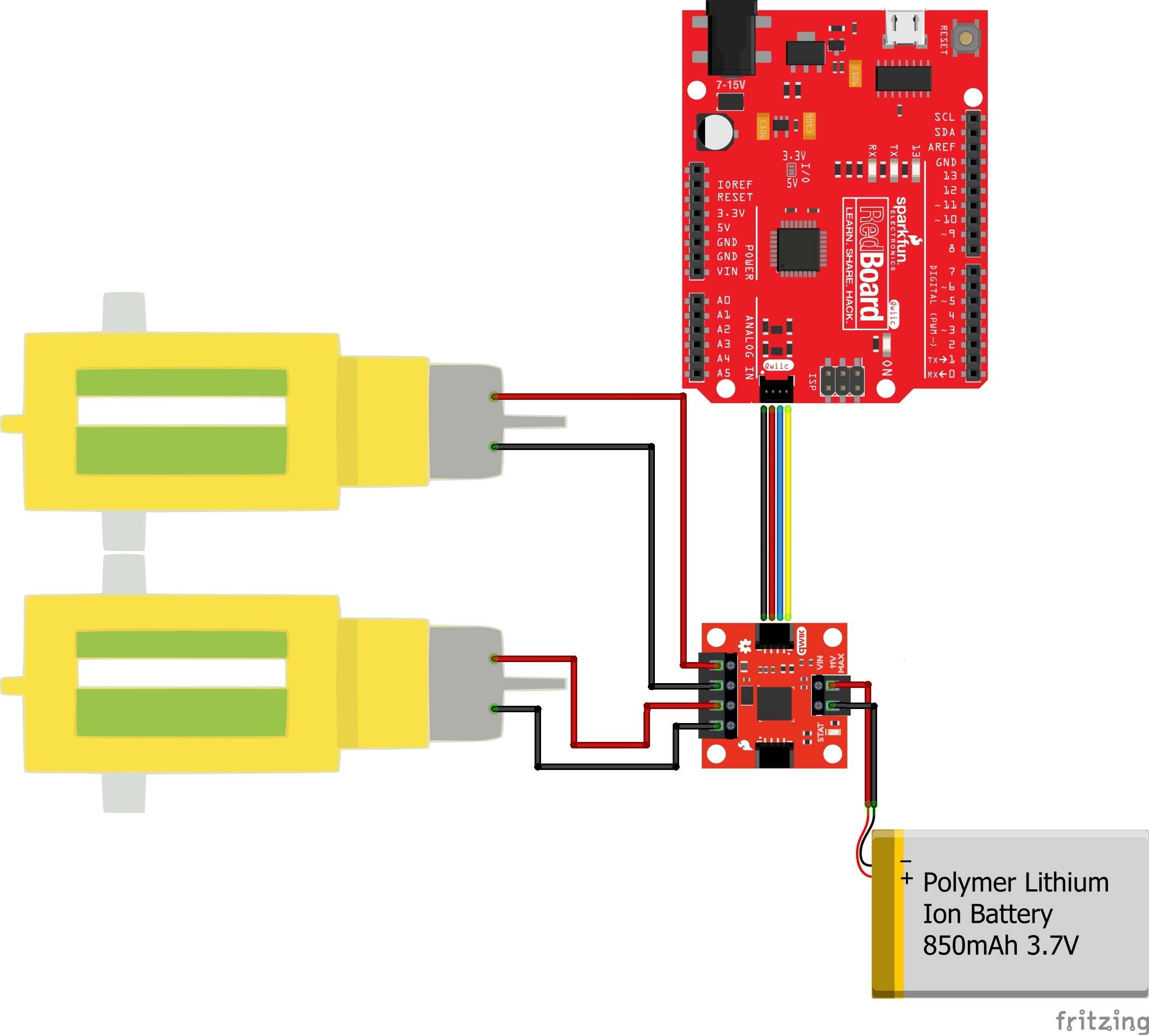
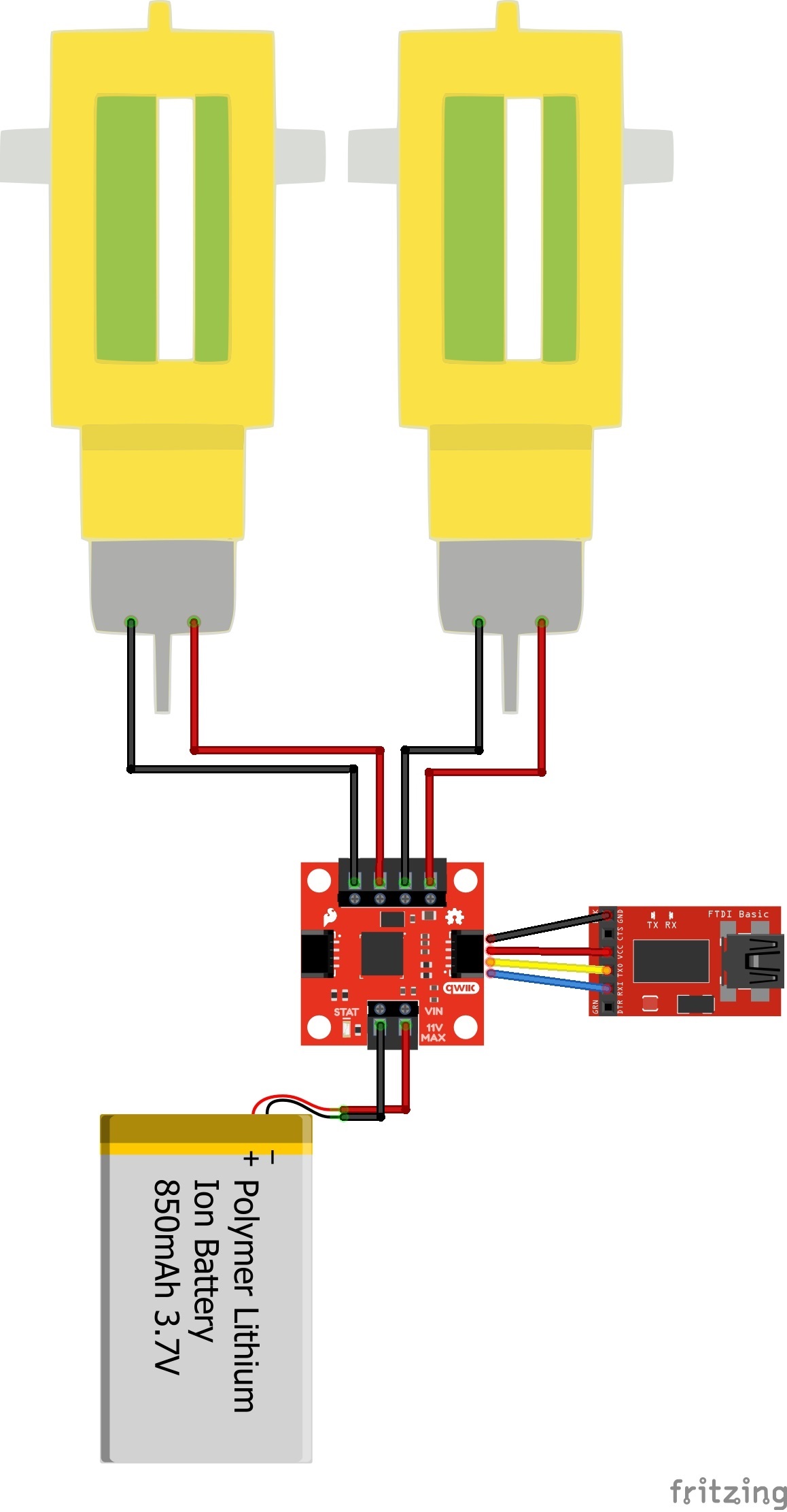
Connect the FTDI to the Qwiic Motor Driver as you see in the Fritzing diagram below. Attach two motors to the driver, one between A1 and A2, and the other between B1 and B2.
Example Commands
When you're ready, make sure you have the correct COM port selected in your Arduino IDE, open a Serial Monitor, and send the following commands:
"R01"
This will read the ID register and return 0xA9
"M0F50"
This will tell motor 0 to drive at half speed, forward -- But nothing will happen yet!
"E"
This will enable all drivers. Motor 0 should begin spinning at half speed.
"M1R100"
This will tell motor 1 to drive at full speed in reverse. Now both should be spinning opposite directions.
"D"
D will disable both motors, which will stop spinning.
See the section UART Commands in the Serial Controlled Motor Driver Hookup Guide for a full command listing.
Need inspiration? Check out some of the Qwiic or motor related tutorials!
Or check out this blog post for some ideas.
learn.sparkfun.com | CC BY-SA 3.0 | SparkFun Electronics | Niwot, Colorado