GPS-RTK Hookup Guide
 Nate
Nate Introduction
The NEO-M8P-2 module is great module for high accuracy GNSS and GPS location solutions including RTK. The NEO-M8P-2 is unique in that it is was one of the first modules from u-blox capable of both rover and base station operations. The ‘-2’ designation means this module has survey-in mode allowing the module to become a base station and produce RTCM 3.x correction data. From here on we will refer to the module as NEO-M8P but it should not be confused with the NEO-M8P-0 module (which is not able to produce RTCM data).
Suggested Reading
Before getting started, be sure to checkout our What is GPS RTK? tutorial and if you want to pre-read a bit have a look at our Getting Started with U-Center.
I2C
Serial Basic Hookup Guide
What is GPS RTK?
Getting Started with U-Center for u-blox
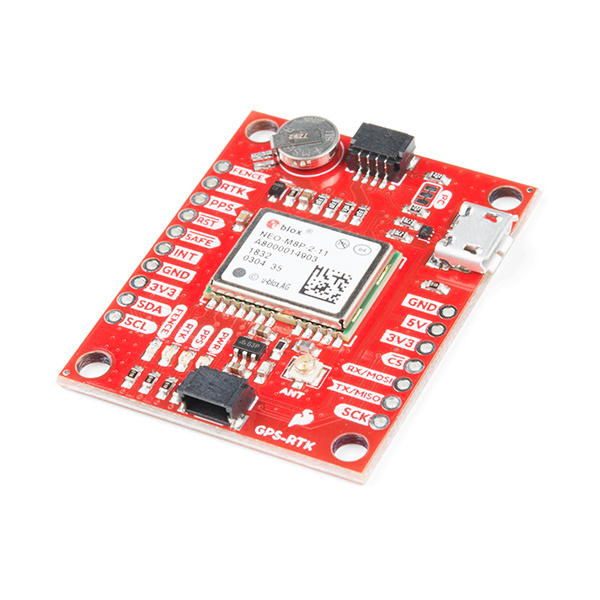
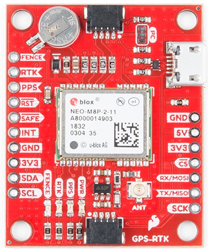
Hardware Overview
Communication Ports
The NEO-M8P-2 is unique in that it has four communication ports which are all active simultaneously. You can read NMEA data over I2C while you send configuration commands over the UART and vice/versa. The only limit is that the SPI pins are mapped onto the I2C and UART pins so it’s either SPI or I2C+UART. The USB port is available at all times.
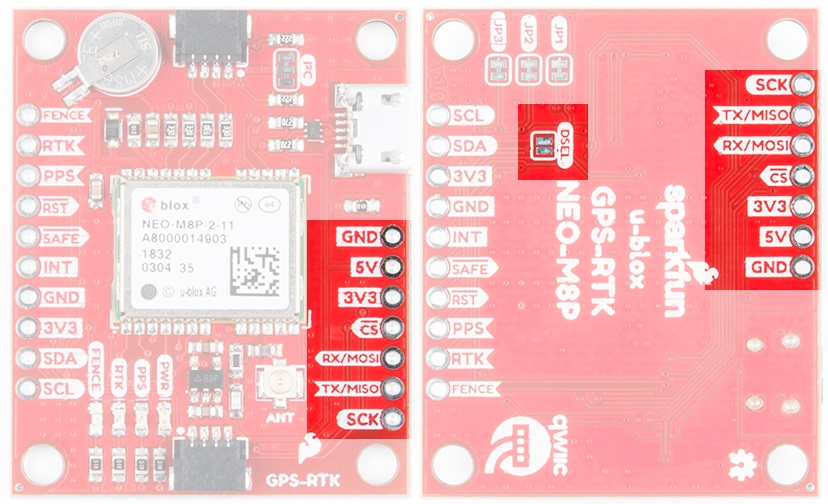
USB
The micro-B connector makes it easy to connect the NEO-M8P to u-center for configuration and quick viewing of NMEA sentences. It is also possible to connect a Raspberry Pi or other SBC over USB. The NEO-M8P enumerates as a serial COM port and it is a seperate serial port from the UART interface. See Getting Started with U-Center for more information about getting the USB port to be a serial COM port.
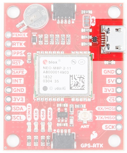
A 3.3V regulator is provided to regulate the 5V USB down to 3.3V the module requires. External 5V can be applied or a direct feed of 3.3V can be provided. Note that if you’re provide the board with 3.3V directly it should be a clean supply with minimal noise (less than 50mV VPP ripple is ideal for precision locating).
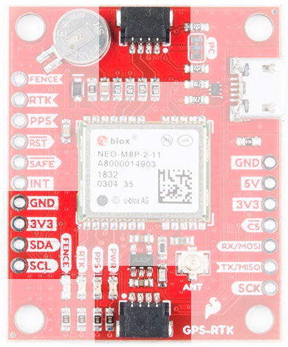
I2C (a.k.a DDC)
The u-blox NEO-M8P has a "DDC" port which is really just an I2C port (without all the fuss of trademark issues). All features are accessible over the I2C ports including reading NMEA sentences, sending UBX configuration strings, piping RTCM data into the module, etc. We’ve written a handful of sketches and an Arduino library to aid in using the NEO-M8P over I2C in a snap. You can get the library through the Arduino library manager by searching 'SparkFun u-blox GNSS'. Checkout the SparkFun u-blox GNSS Arduino Library section for more information.
UART/Serial
The classic serial pins are available on the NEO-M8P but are shared with the SPI pins. Because USB covers most serial needs we didn’t label the UART pins explicitly. By default the UART pins are enabled. Be sure the DSEL jumper on the rear of the board is open.
- MISO = TX out from NEO-M8P
- MOSI = RX into NEO-M8P
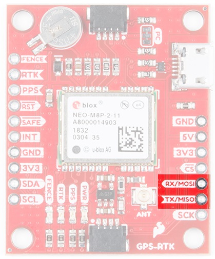
SPI
The NEO-M8P can also be configured for SPI communication. By default the SPI port is disable. To enable SPI close the DSEL jumper on the rear of the board. Closing this jumper will disable the UART and I2C interfaces.
Control Pins
The control pins are highlighted below.
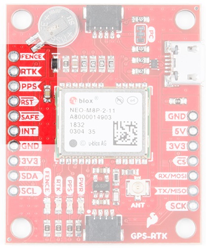
These pins are used for various extra control of the NEO-M8P:
- FENCE: Geofence output pin. Configured with U-Center. Will go high or low when a geofence is setup. Useful for triggering alarms and actions when the module exits a programmed perimeter.
- RTK: RTK output pin. Remains high when module is normal GPS mode. Begins blinking when RTCM corrections are received and module enters RTK float mode. Goes low when module enters RTK fixed mode and begins outputting cm-level accurate locations.
- PPS: Pulse-per-second output pin. Begins blinking at 1Hz when module gets basic GPS/GNSS position lock.
- RST: Reset input pin. Pull this line low to reset the module.
- SAFE: Safeboot input pin. This is required for firmware updates to the module and generally should not be used or connected.
- INT: Interrupt input/output pin. Can be configured using U-Center to bring the module out of deep sleep or to output an interrupt for various module states.
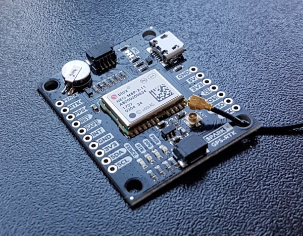
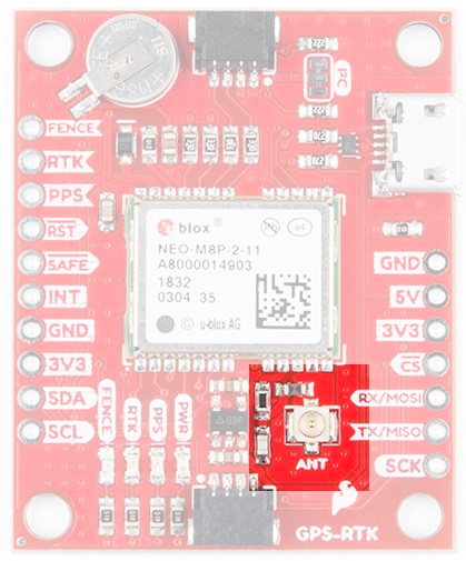
Antenna
The NEO-M8P requires a good quality GPS or GNSS (preferred) antenna. A U.FL connector is provided. Note: U.FL connectors are rated for only a few mating cycles (about 30) so we recommend you set it and forget it. A U.FL to SMA cable threaded through the mounting hole provides a robust connection that is also easy to disconnect at the SMA connection if needed. Low-cost magnetic GPS/GNSS antennas can be used (checkout the u-blox white paper) but a 4” / 10cm metal disc is required to be placed under the antenna as a ground plane.
LEDs
The board includes four status LEDs as indicated in the image below.
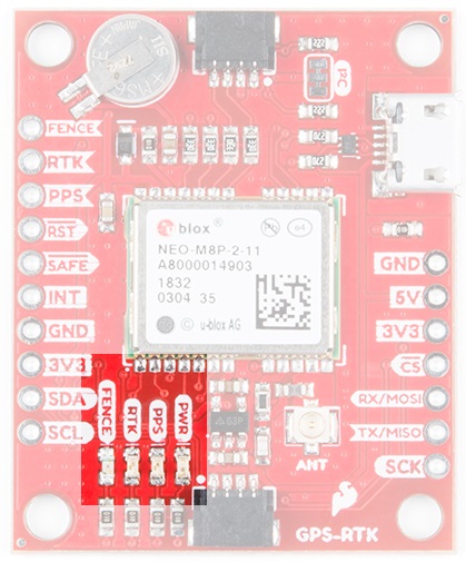
The power (PWR) LED will illuminate when 3.3V is activated either over USB or via the Qwiic bus.
The pulse per second (PPS) LED will illuminate with each successful update once a position lock has been achieved.
The RTK LED will be illuminated constantly upon power up. Once RTCM data has been successfully received it will begin to blink. This is a good way to see if the NEO-M8P is getting RTCM from various sources.
The FENCE LED can be configured to turn on/off for geofencing applications.
Jumpers
There are four jumpers located on the back of the board to configure the GPS-RTK.
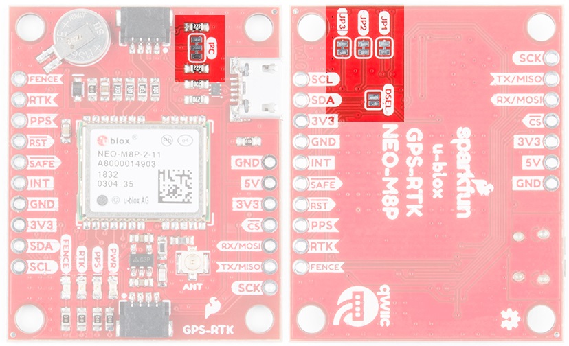
Closing DSEL enables the SPI interface and disables the UART and I2C interfaces. USB will still function.
Cutting the I2C jumper will remove the 2.2k Ohm resistors from the I2C bus. If you have many devices on your I2C bus you may want to remove these jumpers. Not sure how to cut a jumper? Read here!
Jumpers JP1, JP2, JP3, are provided on the rear of the board to allow isolation of the various status LEDs.
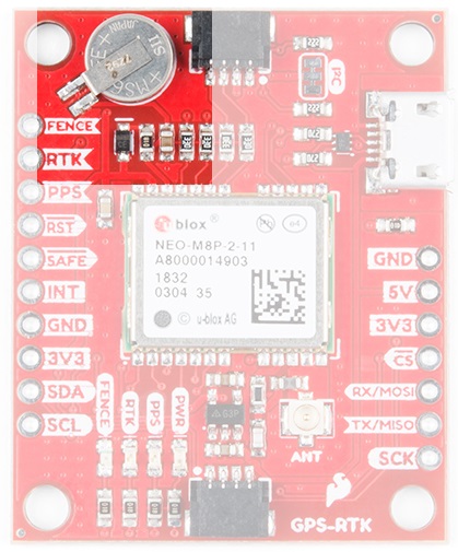
Backup Battery
The MS621FE rechargeable battery maintains the battery backed RAM (BBR) on the NEO-M8P. This allows for much faster position locks. The BBR is also used for module configuration retention. The battery is automatically trickle charged when power is applied and should maintain settings and GNSS orbit data for up to two weeks without power.
Connecting an Antenna
U.FL connectors are very good but they are a designed to be implemented inside a small embedded application like a laptop. Exposing a U.FL connector to the wild risks it getting damaged. To prevent damaging the U.FL connection we recommend threading the U.FL cable through the stand-off hole, then attach the U.FL connectors. This will provide a great stress relief for the antenna connection. Now attach your SMA antenna of choice.

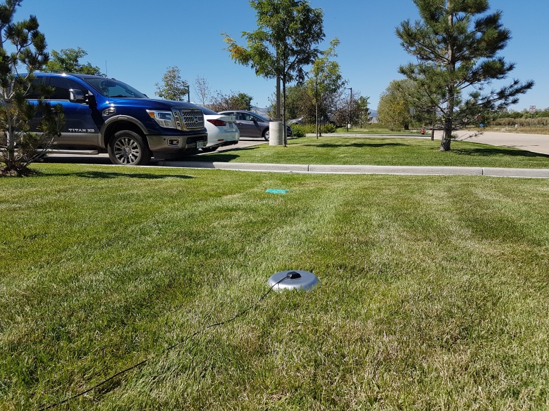
If you’re indoors you must run an SMA extension cable long enough to locate the antenna where it has a clear view of the sky. That means no trees, buildings, walls, vehicles, or concrete metally things between the antenna and the sky. Be sure to mount the antenna on a 4”/10cm metal ground plate to increase reception.
Connecting the GPS-RTK to a Correction Source
Before you go out into the field it’s good to understand how to get RTCM data and how to pipe it to the GPS-RTK. For this example we will show how to get correction data from the UNAVCO network, pull that data in using RTKLIB, and pipe it down over serial to the GPS-RTK.
Required Materials
- 1x GPS-RTK
- 1x L1/L2 GNSS Antenna
- 1x Metal Plate of 4” or larger
- 1x SMA extension cable (if needed to get a clear view of the sky)
- 2x micro-B USB cable
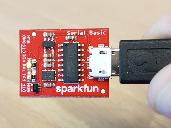
- 1x Serial Basic
- A few jumper wires
Required Software
- Credentials with a free RTCM provider such as UNAVCO
- U-Center
- Download and unzip RTKLIB. We will be using 2.4.2.
UNAVCO has fairly good coverage in the USA. Using their interactive map find a station that is near your location. It’s ok if it is more than 10km (6 miles) away, we’re just practicing.
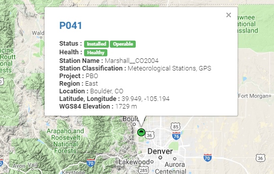
Site P041 is pretty close to SparkFun HQ. We’ll be using it. To access UNAVCO data feeds you will need to send an email to rtgps@unavco.org to request credentials. Let UNAVCO know if you are affiliated with any business, school, or organization and if you are using the account for personal use. Access to UNAVCO is free; I believe they need this information for reporting on their grant funding.
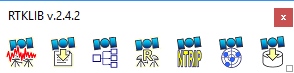
Once you have your UNAVCO credentials open RTKLIB (in Windows run rtklaunch.exe). This small window allows you to launch the various RTK programs. For this tutorial we’ll be using RTKNAVI, the second button from the right.
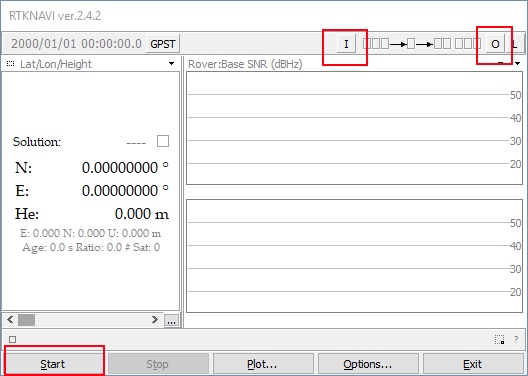
RTKNAVI allows you to connect to RTCM feeds from various providers, including UNAVCO. Click on the small “I” button.
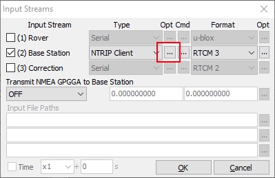
From the input stream window click the check box next to ‘Base Station’, select NTRIP Client from the dropdown, and the RTCM 3 format. Next click on the small three dots under Opt - this will open the NTRIP client configuration options.
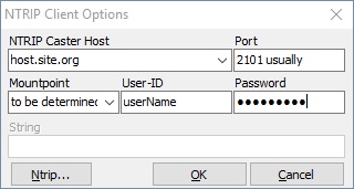
Enter the UNAVCO domain, port, and credentials that you were issued. Next click on the Ntrip... button. This will launch the Ntrip browser so that we can locate the P041 station.
Ntrip browser allows you to connect to different providers and view what streams are available. I wish it was as simple as being able to search for ALL the RTCM streams near a given location but no option currently exists. Instead, we must connect to each provider and see what locations they provide, and what type of correction streams are produced by a given location. Remember, the NEO-M8P only works with RTCM 3.x.

This list is quite large and we’re looking for P041. Click on the Mountpoint column header to sort the list alphabetically.
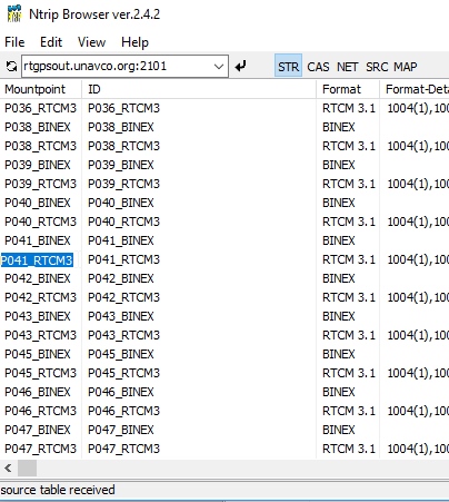
Once we have P041 located, we want the RTCM feed. Copy and paste that mountpoint back into RTKNAVI into the 'Mountpoint' box. Once you've entered all your credentials and mountpoint, click OK to close the NTRIP Client Options window. You can also close the Ntrip browser.
The input stream should be configured so click OK in the Input Stream window to complete configuration. Click 'Start' from the RTKNAVI window to test the connection to the UNAVCO server.
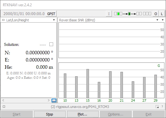
Success! We are receiving a stream. Now we need to output this data. Click the L button for ‘Logging’.
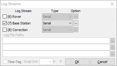
We want to log the Base Station stream to the serial port so now is a good time to connect your Serial Basic or FTDI board. Once the board enumerates, you should have a new serial port. If you run into problems or need drivers checkout the Serial Basic Hookup Guide.
Click the ‘...’ button to configure your serial port. Note that you’ll need to select the same baud rate as your GPS-RTK module is configured for. By default, the NEO-M8P communicates at 9600bps 8-N-1, so use this setting. Once you have things configured properly the TX LED on the Serial basic should blink once per second indicating the UNAVCO server is pushing data all the way down to the TX pin on the Serial Basic.
The RTCM pipe is complete. Now we need to connect the "last inch" to the NEO-M8P.
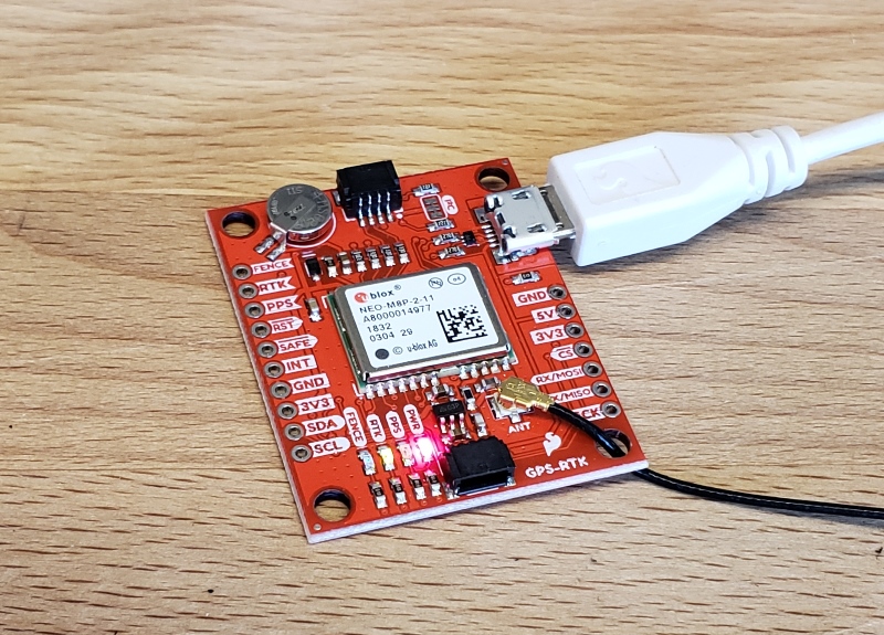
Time to power up up the GPS-RTK board. Attach a micro-B cable to the GPS-RTK board. The power LED should illuminate. Open the U-Center software from U-blox. Be sure to read Getting Started with U-Center if you haven’t already. Thankfully, the NEO-M8P's default configuration allows it to receive RTCM correction data without any further changes. All you need to do is feed the NEO-M8P with serial data and it will begin calculating the high precision location solution.
Select the correct COM port and begin viewing the NMEA data. You should have a position lock very quickly. Once the PPS LED begins to blin0,k you are ready to start piping RTCM data to the GPS-RTK board.
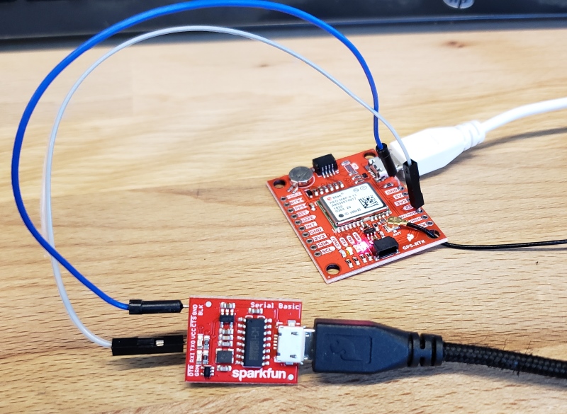
The Serial Basic board should still be blinking once a second with RTCM data from the UNAVCO server. Using two jumper wires connect GND on the Serial Basic to GND on the GPS-RTK. Next, connect TXO to the MOSI pin on the GPS-RTK. The MOSI pin is the RX UART pin by default (when DSEL jumper is open). Jumper wires without solder are obviously a precarious setup but we’re just testing things out. Arrange things so the connection is semi-permanent. Within a few seconds you should see the RTK LED begin to blink.
Congratulations! Your GPS module has entered RTK float mode. When the RTK LED turns off completely then the module has solved the carrier ambiguities and entered RTK fixed mode and is outputting centimeter level positions!
Once you have the GPS-RTK receiving RTCM correction data successfully, you can begin planning how to obtain and deliver the RTCM data to the GPS-RTK. The options are vast and varied:
- It is possible to pull get Ntrip data on an Android app and pipe it over a Bluetooth serial device like the Bluetooth Mate Silver. It’s trivial to connect a Bluetooth serial device to the GPS-RTK serial pins.
- If you need maximum portability a radio link can be the lowest power, smallest footprint. SparkFun offers a variety of LoRa radios and antennas. With the help of a microcontroller these radios can pipe data from the LoRa backhaul over an Qwiic I2C port, serial, even SPI.
- If your end application already requires an internet connection such as GSM or LTE-CAT, then a microcontroller could feasibly connect to an Ntrip server over the internet and pipe the RTCM data over a serial or an I2C connection on the GPS-RTK.
SparkFun u-blox Arduino Library
The GPS-RTK Arduino library enables the reading of NMEA data over I2C as well as sending binary UBX configuration commands over I2C. This is helpful for configuring advanced modules like the NEO-M8P-2.
The SparkFun u-blox Arduino library can be downloaded with the Arduino library manager by searching 'SparkFun u-blox GNSS' or you can grab the zip here from the GitHub repository:
Once you have the library installed checkout the various examples.
- Example1: Read NMEA sentences over I2C using u-blox module SAM-M8Q, NEO-M8P, etc
- Example2: Parse NMEA sentences using MicroNMEA library. This example also demonstrates how to overwrite the
processNMEAfunction so that you can direct the incoming NMEA characters from the u-blox module to any library, display, radio, etc that you prefer. - Example3: Get latitude, longitude, altitude, and satellites in view (SIV). This example also demonstrates how to turn off NMEA messages being sent out of the I2C port. You’ll still see NMEA on UART1 and USB, but not on I2C. Using only UBX binary messages helps reduce I2C traffic and is a much lighter weight protocol.
- Example4: Displays what type of a fix you have the two most common being none and a full 3D fix. This sketch also shows how to find out if you have an RTK fix and what type (floating vs. fixed).
- Example5: Shows how to get the current speed, heading, and dilution of precision.
- Example6: Demonstrates how to increase the output rate from the default 1 per second to many per second; up to 30Hz on some modules!
- Example7: Older modules like the SAM-M8Q utilize an older protocol (version 18) whereas the newer modules like the ZED-F9P depricate some commands using the latest protocol (version 27). This sketch shows how to query the module to get the protocol version.
- Example8: u-blox modules use I2C address 0x42 but this is configurable via software. This sketch will allow you to change the module’s I2C address.
- Example9: Altitude is not a simple measurement. This sketch shows how to get both the ellipsoid based altitude and the MSL (mean sea level) based altitude readings.
- Example10: Sometimes you just need to do a hard reset of the hardware. This sketch shows how to set your u-blox module back to factory default settings.
- NEO-M8P: Examples specific for the NEO-M8P.
- NEO-M8P Example1: Send UBX binary commands to enable RTCM sentences on U-blox NEO-M8P-2 module. This example is one of the steps required to setup the NEO-M8P as a base station. For more information have a look at the u-blox manual for setting up an RTK link.
- NEO-M8P Example2: This example extends the previous example sending all the commands to the NEO-M8P-2 to have it operate as a base. Additionally the
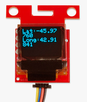
processRTCMfunction is exposed. This allows the user to overwrite the function to direct the RTCM bytes to whatever connection the user would like (radio, serial, etc). - NEO-M8P Example3: This is the same example as NEO-M8P's Example2. However, the data is sent to a serial LCD via I2C.
- ZED-F9P: Examples specific for the ZED-F9P.
- ZED-F9P Example1: This module is capable of high precision solutions. This sketch shows how to inspect the accuracy of the solution. It’s fun to watch our location accuracy drop into the millimeter scale.
- ZED-F9P Example2: The ZED-F9P uses a new u-blox configuration system of VALGET/VALSET/VALDEL. This sketch demonstrates the basics of these methods.
- ZED-F9P Example3: Setting up the ZED-F9P as a base station and outputting RTCM data.
- ZED-F9P Example4: This is the same example as ZED-F9P's Example3. However, the data is sent to a serial LCD via I2C.
This SparkFun u-blox library really focuses on I2C because it's faster than serial and supports daisy-chaining. The library also uses the UBX protocol because it requires far less overhead than NMEA parsing and does not have the precision limitations that NMEA has.
Setting Up A Base Station
If you’re located further than 20km from a correction station you can create your own station using the NEO-M8P-2. u-blox provides a great setup guide showing the various settings needed via u-center. We’ll be covering how to setup the GPS-RTK using I2C commands only. This will enable a headless (computerless) configuration of a base station that outputs RTCM correction data. You can watch a brief demo of this in the product video:
Before getting started we recommend you configure the module using u-center. Checkout our tutorial on using U-Center then read the u-blox datasheet on getting the NEO-M8P configured for RTK using U-Center. Once you’ve been successful controlling the module in the comfort of your lab, then consider heading outdoors.
For this exercise we’ll be using the following parts:
- SparkFun GPS-RTK Board
- SparkFun BlackBoard makes I2C easy
- microB Cable if you need one
- Antenna L1/L2 GNSS 3-5V Magnetic Mount
- GPS Antenna Ground Plate
- U.FL to SMA Cable
- Two Qwiic Cables
- 20x4 SerLCD with Qwiic Adapter soldered on
- 1x 20+ft SMA extension can be handy when first experimenting with base stations so you can sit indoors with a laptop and analyze the output of the GPS-RTK
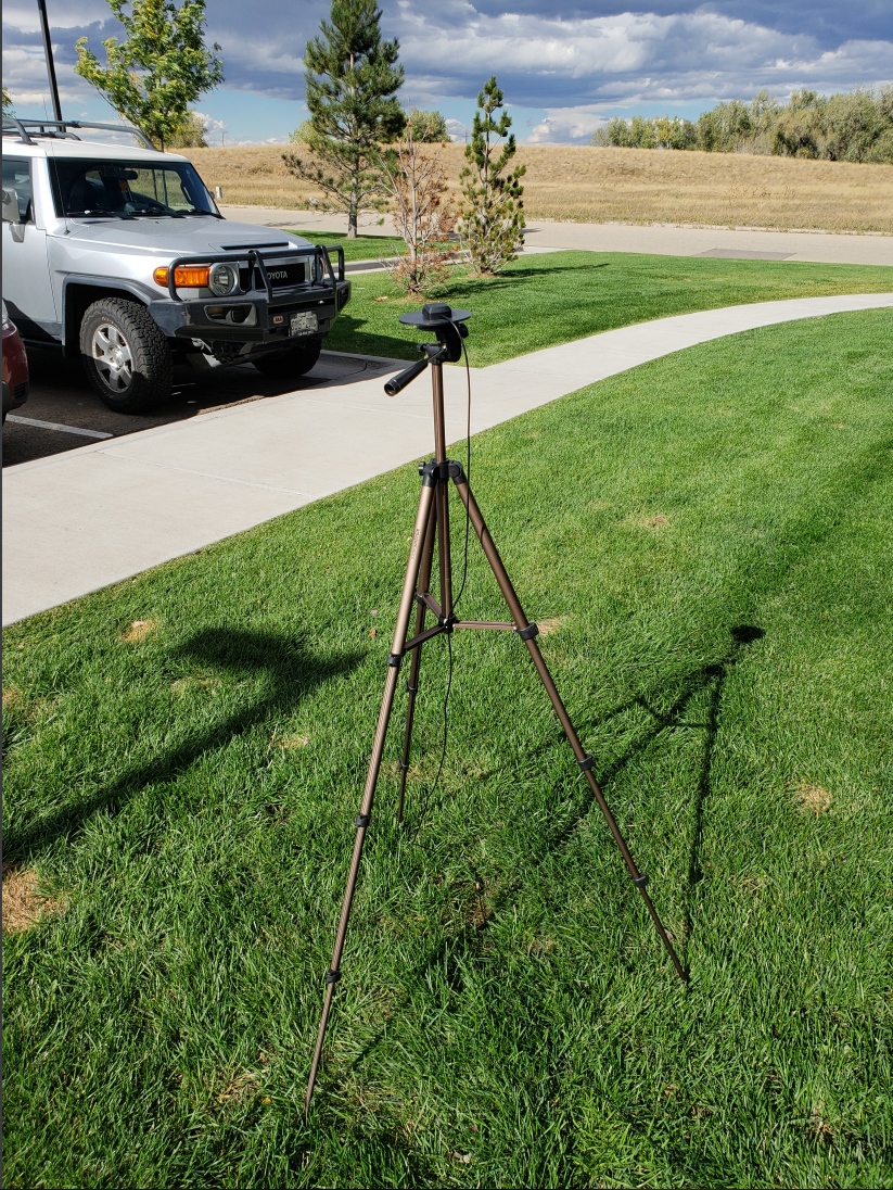
- A standard camera tripod
The NEO-M8P-2 can be configured using Serial, SPI, or I2C. We’re fans of the daisychain-ability of I2C so we’ll be focusing on the Qwiic system. For this exercise we’ll be connecting the an LCD and GPS-RTK to a BlackBoard using two Qwiic cables.
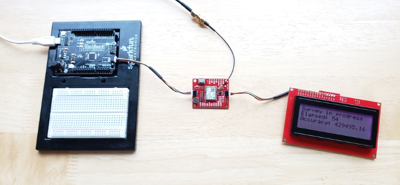
For the antenna, you’ll need a clear view of the sky. The better your antenna position the better your accuracy and performance of the system. We designed the GPS Antenna Ground Plate to make this setup easy. The plate has a ¼” threaded hole that threads directly onto a camera tripod. The plate thickness was chosen to be thick enough so that the threaded screw is flush with the plate so it won’t interfere with the antenna. Not sure why we’re using a ground plate? Read the u-blox white paper on using low-cost GNSS antennas with RTK. Mount your magnetic mount antenna and run the SMA cable to the U.FL to SMA cable to the GPS-RTK board.
There are only three steps to initiating a base station:
- Enable Survey-In mode for 5 minutes (300 seconds)
- Enable RTCM output messages
- Begin transmitting the RTCM packets over the backhaul of choice
Be sure to grab the SparkFun u-blox GNSS Arduino Library. You can easily install this via the library manager by searching ‘SparkFun u-blox GNSS’. Once installed click on File->Examples->SparkFun_u-blox_GNSS_Arduino_Library.
The NEO-M8P subfolder houses a handful of sketches specific to its setup. Example3 demonstrates how to send the various commands to the GPS-RTK to enable Survey-In mode. Let’s discuss the important bits of code.
language:c
response = myGNSS.enableSurveyMode(300, 2.000); //Enable Survey in, 300 seconds, 2.0m
The library is capable of sending UBX binary commands with all necessary headers, packet length, and CRC bytes over I2C. The enableSurveyMode(minimumTime, minimumRadius) command does all the hard work to tell the module to go into survey mode. The module will begin to record lock data and calculate a 3D standard deviation. The survey-in process ends when both the minimum time and minimum radius are achieved. u-blox recommends 300 seconds (5 minutes) and a radius of 2m. With a clear view of the sky, with a low cost GNSS antenna mounted to a ground plate we’ve seen the survey complete at 301 seconds with a radius of around 1.5m.
language:c
response &= myGNSS.enableRTCMmessage(UBX_RTCM_1005, UBX_RTCM_I2C_PORT, 1); //Enable message 1005 to output through I2C port, message every second
response &= myGNSS.enableRTCMmessage(UBX_RTCM_1077, UBX_RTCM_I2C_PORT, 1);
response &= myGNSS.enableRTCMmessage(UBX_RTCM_1087, UBX_RTCM_I2C_PORT, 1);
response &= myGNSS.enableRTCMmessage(UBX_RTCM_1230, UBX_RTCM_I2C_PORT, 10); //Enable message every 10 seconds
These four lines enable the four RTCM output messages needed for a second GPS-RTK to receive correction data. Once these sentences have been enabled (and assuming a survey process is complete) the GPS-RTK base module will begin outputting RTCM data every second after the NMEA sentences (the RTCM_1230 sentence will be output once every 10 seconds). You can view an example of what this output looks like here.
The size of the RTCM correction data varies but in general it is approximately 350 bytes every second (~500 bytes every 10th second when 1230 is transmitted).
language:c
//This function gets called from the SparkFun u-blox GNSS Arduino Library.
//As each RTCM byte comes in you can specify what to do with it
//Useful for passing the RTCM correction data to a radio, Ntrip broadcaster, etc.
void SFE_UBLOX_GNSS::processRTCM(uint8_t incoming)
{
  //Let's just pretty-print the HEX values for now
  if (myGNSS.rtcmFrameCounter % 16 == 0) Serial.println();
  Serial.print(" ");
  if (incoming < 0x10) Serial.print("0");
  Serial.print(incoming, HEX);
}
If you have a ‘rover’ in the field in need of correction data you’ll need to get the RTCM bytes to the rover. The SparkFun u-blox library automatically detects the difference between NMEA sentences and RTCM data. The processRTCM() function allows you to ‘pipe’ just the RTCM correction data to the channel of your choice. Once the base station has completed the survey and has the RTCM messages enabled, your custom processRTCM() function can pass each byte to any number of channels:
- A wireless system such as LoRa or Cellular
- Posting the bytes over the internet using WiFi or wired ethernet over an Ntrip caster
- Over a wired solution such as RS485
The power of the processRTCM() function is that it doesn’t care; it presents the user with the incoming byte and is agnostic about the back channel.
What about configuring the rover? u-blox designed the NEO-M8P to automatically go into RTK mode once RTCM data is detected on any of the ports. Simply push the RTCM bytes from your back channel into one of the ports (UART, SPI, I2C) on the rover's GPS-RTK and the location accuracy will go from meters to centimeters. The rover's NMEA messages will contain the improved Lat/Long data and you'll know where you are with mind-bending accuracy. It’s a lot of fun to watch!
NMEA and RTK
Can I Really Use NMEA with a High Precision GPS Receiver?
Yes! Except that NMEA sentences are right on the edge of enough precision. NMEA sentences look something like this:
language:bash
$GNGGA,012911.00,4003.19080,N,10416.95542,W,1,12,0.75,1647.1,M,-21.3,M,,*4F
NMEA outputs coordinates in the ddmm.mmmmm format. So what is the weight of the least significant digit? Said differently, what is the impact of one digit change?
language:bash
104 16.95542
vs
language:bash
104 16.95543
If we know 1 degree of latitude is 111.3km at the equator, we can glean the change of a fraction of a minute:
- 1 degree = 60 minutes
- 1 minute = 1 degree/60 = 111.32km / 60 = 1.855km
- 1 minute = 1855m
- 0.1min = 185.5m
- 0.01min = 18.55m
- 0.001min = 1.855m
- 0.0001min = .1855m = 185.5mm
- 0.00001min = 0.0185m = 18.55mm = 1.855cm
Using the NMEA sentence, the NEO-M8P will only be able to communicate a change of ~1.5cm location change for each digit in the 5th position. This is pretty close to the 2.5cm accuracy of the module. If you want additional precision, you should consider using the UBX protocol which can output up to 8 digits of precision in dd.dddddddd format which will get you down to 1.11mm of precision!
Resources and Going Further
Ready to get hands-on with GPS?
We've got a page just for you! We'll walk you through the basics of how GPS works, the hardware needed, and project tutorials to get you started.
Have fun with your new found super power: sub decimeter grade GPS!
For more on the GPS-RTK, check out the links below:
- Schematic (PDF)
- Eagle Files (ZIP)
- Example RTCM output from the NEO-M8P-2
- NEO-M8P-2 Datasheet (PDF)
- Using U-Center to configure the NEO-M8P for base station RTCM output
- NEO-M8P Hardware Integration Manual (PDF)
- NEO-M8P Product Summary (PDF)
- u-blox M8 Series Protocol
- U-blox ECCN notice
- GitHub
- SFE Product Showcase
Need some inspiration? Check out some of these related tutorials: