GPS-RTK Hookup Guide
 Nate
Nate 
Hardware Overview
Communication Ports
The NEO-M8P-2 is unique in that it has four communication ports which are all active simultaneously. You can read NMEA data over I2C while you send configuration commands over the UART and vice/versa. The only limit is that the SPI pins are mapped onto the I2C and UART pins so it’s either SPI or I2C+UART. The USB port is available at all times.
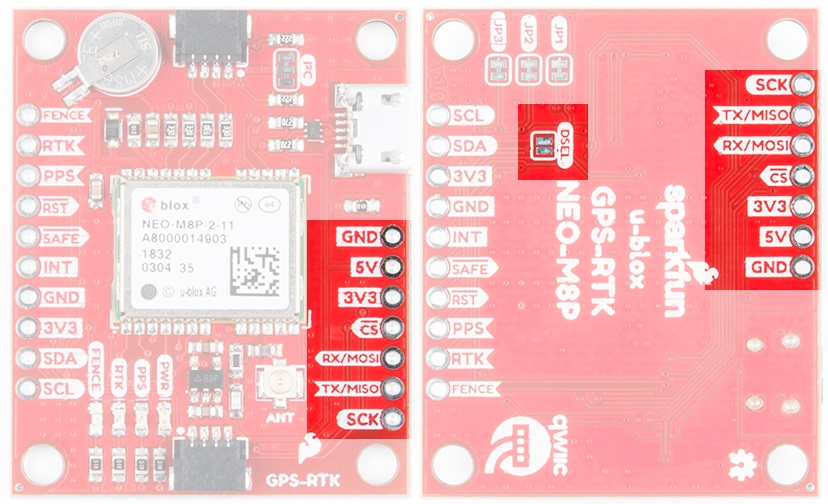
USB
The micro-B connector makes it easy to connect the NEO-M8P to u-center for configuration and quick viewing of NMEA sentences. It is also possible to connect a Raspberry Pi or other SBC over USB. The NEO-M8P enumerates as a serial COM port and it is a seperate serial port from the UART interface. See Getting Started with U-Center for more information about getting the USB port to be a serial COM port.
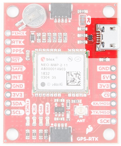
A 3.3V regulator is provided to regulate the 5V USB down to 3.3V the module requires. External 5V can be applied or a direct feed of 3.3V can be provided. Note that if you’re provide the board with 3.3V directly it should be a clean supply with minimal noise (less than 50mV VPP ripple is ideal for precision locating).
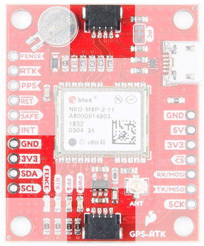
I2C (a.k.a DDC)
The u-blox NEO-M8P has a "DDC" port which is really just an I2C port (without all the fuss of trademark issues). All features are accessible over the I2C ports including reading NMEA sentences, sending UBX configuration strings, piping RTCM data into the module, etc. We’ve written a handful of sketches and an Arduino library to aid in using the NEO-M8P over I2C in a snap. You can get the library through the Arduino library manager by searching 'SparkFun u-blox GNSS'. Checkout the SparkFun u-blox GNSS Arduino Library section for more information.
UART/Serial
The classic serial pins are available on the NEO-M8P but are shared with the SPI pins. Because USB covers most serial needs we didn’t label the UART pins explicitly. By default the UART pins are enabled. Be sure the DSEL jumper on the rear of the board is open.
- MISO = TX out from NEO-M8P
- MOSI = RX into NEO-M8P
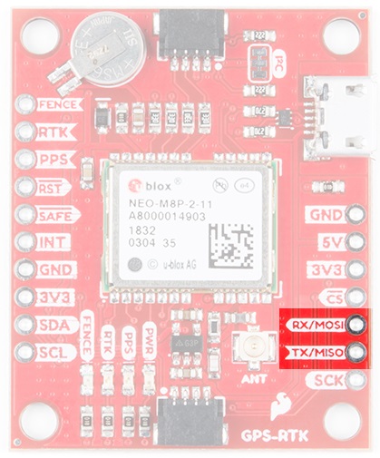
SPI
The NEO-M8P can also be configured for SPI communication. By default the SPI port is disable. To enable SPI close the DSEL jumper on the rear of the board. Closing this jumper will disable the UART and I2C interfaces.
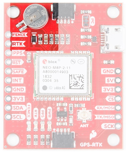
Control Pins
The control pins are highlighted below.
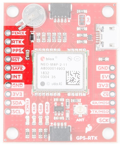
These pins are used for various extra control of the NEO-M8P:
- FENCE: Geofence output pin. Configured with U-Center. Will go high or low when a geofence is setup. Useful for triggering alarms and actions when the module exits a programmed perimeter.
- RTK: RTK output pin. Remains high when module is normal GPS mode. Begins blinking when RTCM corrections are received and module enters RTK float mode. Goes low when module enters RTK fixed mode and begins outputting cm-level accurate locations.
- PPS: Pulse-per-second output pin. Begins blinking at 1Hz when module gets basic GPS/GNSS position lock.
- RST: Reset input pin. Pull this line low to reset the module.
- SAFE: Safeboot input pin. This is required for firmware updates to the module and generally should not be used or connected.
- INT: Interrupt input/output pin. Can be configured using U-Center to bring the module out of deep sleep or to output an interrupt for various module states.
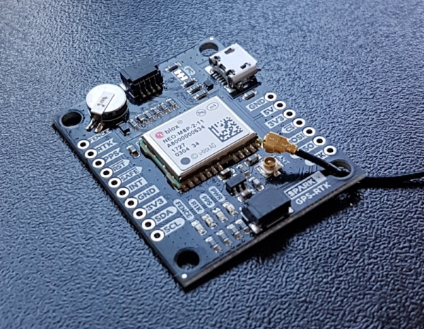
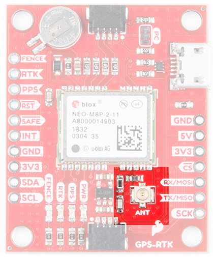
Antenna
The NEO-M8P requires a good quality GPS or GNSS (preferred) antenna. A U.FL connector is provided. Note: U.FL connectors are rated for only a few mating cycles (about 30) so we recommend you set it and forget it. A U.FL to SMA cable threaded through the mounting hole provides a robust connection that is also easy to disconnect at the SMA connection if needed. Low-cost magnetic GPS/GNSS antennas can be used (checkout the u-blox white paper) but a 4” / 10cm metal disc is required to be placed under the antenna as a ground plane.
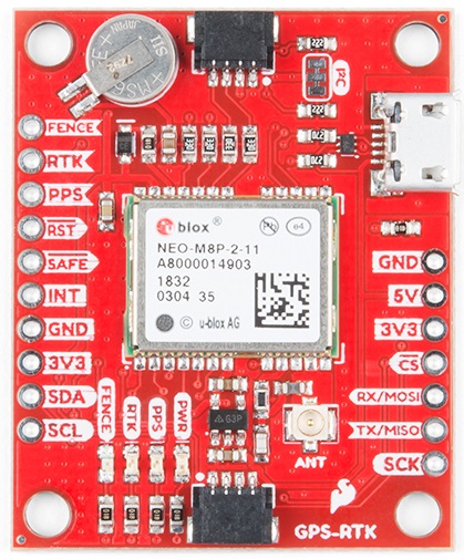
LEDs
The board includes four status LEDs as indicated in the image below.
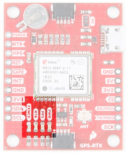
The power (PWR) LED will illuminate when 3.3V is activated either over USB or via the Qwiic bus.
The pulse per second (PPS) LED will illuminate with each successful update once a position lock has been achieved.
The RTK LED will be illuminated constantly upon power up. Once RTCM data has been successfully received it will begin to blink. This is a good way to see if the NEO-M8P is getting RTCM from various sources.
The FENCE LED can be configured to turn on/off for geofencing applications.
Jumpers
There are four jumpers located on the back of the board to configure the GPS-RTK.
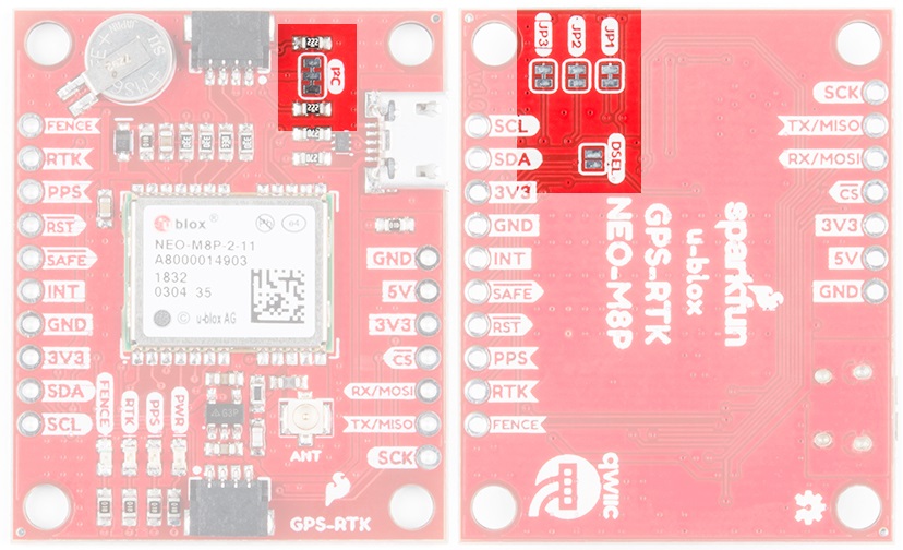
Closing DSEL enables the SPI interface and disables the UART and I2C interfaces. USB will still function.
Cutting the I2C jumper will remove the 2.2k Ohm resistors from the I2C bus. If you have many devices on your I2C bus you may want to remove these jumpers. Not sure how to cut a jumper? Read here!
Jumpers JP1, JP2, JP3, are provided on the rear of the board to allow isolation of the various status LEDs.
Backup Battery
The MS621FE rechargeable battery maintains the battery backed RAM (BBR) on the NEO-M8P. This allows for much faster position locks. The BBR is also used for module configuration retention. The battery is automatically trickle charged when power is applied and should maintain settings and GNSS orbit data for up to two weeks without power.