Getting Started with the RedBot
This Tutorial is Retired!
This tutorial covers concepts or technologies that are no longer current. It's still here for you to read and enjoy, but may not be as useful as our newest tutorials.
 SFUptownMaker
Hardware
RedBot Mainboard
The RedBot Mainboard was designed to be as versatile as possible. It has banks of 3-pin I/O break-outs for easily connecting up LEDs, Sensors, or motors. It also has an integrated [H-Bridge Driver]( (https://cdn.sparkfun.com/assets/learn_tutorials/1/1/0/TB6612FNG.pdf) chip. While we have developed an integrated library for the RedBot, if you want to drive the motors manually - here are the pin outs for the Motor Driver:
LEFT MOTOR:
- Control 1 - Pin 2
- Control 2 - Pin 4
- Motor PWM (Speed) - Pin 5
RIGHT MOTOR:
- Control 1 - Pin 7
- Control 2 - Pin 8
- Motor PWM (Speed) - Pin 6
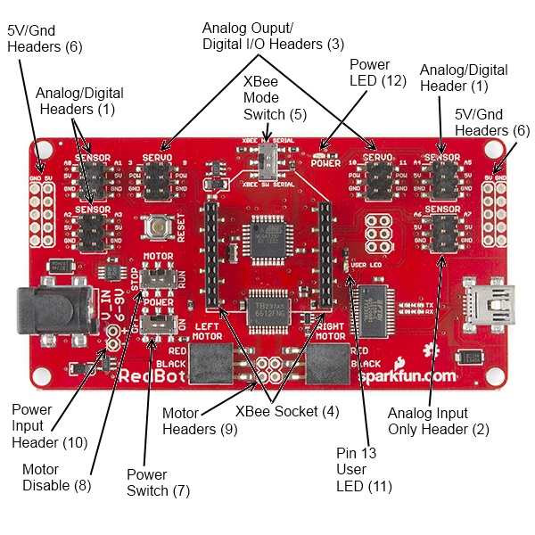
Here's a quick tour of the hardware that's on the board:
Analog/digital headers - These three headers provide one I/O pin, which can be used for analog input as well as digital input or output, as well as 5V power and ground. In addition, the header with A4 and A5 can be used for connecting I2C devices; the RedBot Accelerometer is designed to solder directly to this header, making connecting an accelerometer a snap.
Analog input header - This header provides an additional two analog input pins. These pins can't be used for digital signals, however.
Analog output/digital header - These two headers provide four pins which can be used for either PWM output or regular digital I/O. Note that the power supply for these headers is connected directly to the battery, providing extra umph for servo motors, but devices expecting 5V should not be connected directly to them!
Wireless Socket - The RedBot has a socket for an XBee module, providing easy wireless interfacing.
XBee Mode Switch A switch allows you to select whether the XBee communicates via the standard serial I/O pins (0 and 1, accessible through the built in Serial command set) or via pins 14 and 15 (A0 and A1), using the SoftwareSerial library. Using the software mode will consume two of your analog inputs, however.
5V / GND Headers - Headers are available to allow the user to tap off the 5V and ground signals.
Power Switch - A power switch puts the board into a very low power consumption mode (microamps or less) allowing you to turn the board off without pulling the power connection.
Motor Disable Switch - A motor disable switch allows you to turn off the motor driver so you can program the board without having it drive all over.
Motor Headers - Headers are available to easily connect up the right and left side motors. The motor control is powered by the TB6612FNG Motor Driver.
Power Input Header - A header has also been provided to allow you to access the input supply, either for purposes of driving additional circuitry or to allow more flexibility than the standard barrel jack does for power sources.
DEBUG LED (pin 13) - An LED is connected to pin 13 to allow basic sanity checks that code is loading and running on the board.
Power LED - A power LED will remain lit whenever the power switch is active.
Here's a quick Example program to test your RedBot out with. It spins the left motor forward and reverse, and the spins both motors forward and reverse.
Push the small reset button to restart the program.
language:c
/*******************************************************************************
/ SimpleRedBotDrive Code - no libraries
/
/ Simple example code showing how to spin the right and left motors and braking.
/ This example requires no libraries to run, and has all of the pins used on the
/ RedBot Mainboard defined.
/
/ Before uploading this code to your RedBot, make sure that the RedBot is in a safe
/ place. It will start moving immediately after you upload the program. We suggest
/ placing the RedBot on it's end so that the wheels are up.
/
/ Push the small reset button on the board to run the program again.
/
/ Note: The RedBot Mainboard programs as an Arduino Uno
/******************************************************************************/

// H-Bridge motor driver pins
#define    L_CTRL1   2
#define    L_CTRL2   4
#define    L_PWM     5

#define    R_CTRL1   7
#define    R_CTRL2   8
#define    R_PWM     6

// XBee SW_Serial pins
#define    SW_SER_TX A0
#define    SW_SER_RX A1


/*******************
/ setup function
/*******************/
void setup()
{
    Serial.begin(9600);

    pinMode(L_CTRL1, OUTPUT);  // used as a debug pin for an LED.
    pinMode(L_CTRL2, OUTPUT);  // used as a debug pin for an LED.
    pinMode(L_PWM, OUTPUT);  // used as a debug pin for an LED.

    pinMode(R_CTRL1, OUTPUT);  // used as a debug pin for an LED.
    pinMode(R_CTRL2, OUTPUT);  // used as a debug pin for an LED.
    pinMode(R_PWM, OUTPUT);  // used as a debug pin for an LED.

    pinMode(13, OUTPUT);  // used as a debug pin for an LED.


    // spin the left Motor CW
    leftMotor(255);
    delay(2000);
    leftBrake();
    delay(1000);  // wait for 1000 milliseconds


    // spin the left Motor CCW
    leftMotor(-255);
    delay(2000);
    leftBrake();
    delay(1000);  // wait for 1000 milliseconds

    // spin both motors (drive forward) -- left CW, right CCW
    leftMotor(255);
    rightMotor(-255);
    delay(2000);  // wait for 2000 milliseconds
    leftBrake();
    rightBrake();

    // spin both motors (drive in reverse) -- left CCW, right CW
    leftMotor(-255);
    rightMotor(255);
    delay(2000);  // wait for 2000 milliseconds
    leftBrake();
    rightBrake();

}

/*******************
/ loop function
/*******************/
void loop()
{
    // no code here. All driving code is in the setup() -- so that it runs just once.
}

/*******************************************************************************/
void leftMotor(int motorPower)
{
    motorPower = constrain(motorPower, -255, 255);   // constrain motorPower to -255 to +255
    if(motorPower >= 0)
    {
        // spin CW
        digitalWrite(L_CTRL1, HIGH);
        digitalWrite(L_CTRL2, LOW);
        analogWrite(L_PWM, abs(motorPower));
    }
    else
    {
        // spin CCW
        digitalWrite(L_CTRL1, LOW);
        digitalWrite(L_CTRL2, HIGH);
        analogWrite(L_PWM, abs(motorPower));
    }
}

/*******************************************************************************/
void leftBrake()
{
    // setting both controls HIGH, shorts the motor out -- causing it to self brake.
    digitalWrite(L_CTRL1, HIGH);
    digitalWrite(L_CTRL2, HIGH);
    analogWrite(L_PWM, 0);
}
/*******************************************************************************/
void rightMotor(int motorPower)
{
    motorPower = constrain(motorPower, -255, 255);   // constrain motorPower to -255 to +255
    if(motorPower >= 0)
    {
        // spin CW
        digitalWrite(R_CTRL1, HIGH);
        digitalWrite(R_CTRL2, LOW);
        analogWrite(R_PWM, abs(motorPower));
    }
    else
    {
        // spin CCW
        digitalWrite(R_CTRL1, LOW);
        digitalWrite(R_CTRL2, HIGH);
        analogWrite(R_PWM, abs(motorPower));
    }
}

/*******************************************************************************/
void rightBrake()
{
    // setting both controls HIGH, shorts the motor out -- causing it to self brake.
    digitalWrite(L_CTRL1, HIGH);
    digitalWrite(L_CTRL2, HIGH);
    analogWrite(R_PWM, 0);
}
Magician Chassis
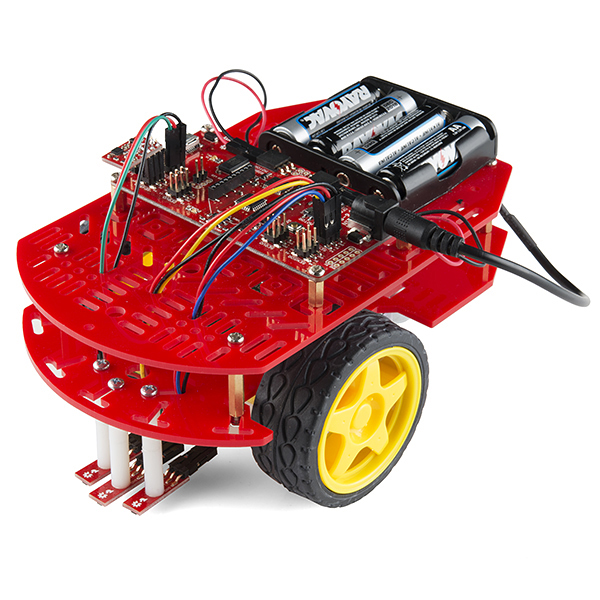
The Magician Chassis is an economical robot platform with a lot of versatility. It features two gearmotors with 65mm wheels and a caster. The chassis plates are cut from acrylic with a wide variety of mounting holes for sensors, controllers, power, etc. The chassis does require some basic assembly but detailed instructions are included.
RedBot Line Follower Sensor
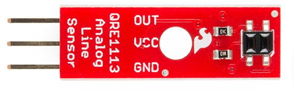
The Line Follower sensor is an add-on for your RedBot that gives your robot the ability to detect lines or nearby objects. The sensor works by detecting reflected light coming from its own infrared LED. By measuring the amount of reflected infrared light, it can detect transitions from light to dark (lines) or even objects directly in front of it.
The sensor has a 3-pin header which connects directly to the RedBot Mainboard via female to female jumper wires. Use the included RedBot library to detect lines or objects. A mounting hole lets you easily connect one or more of these to the front or back of your robot chassis.
RedBot Accelerometer
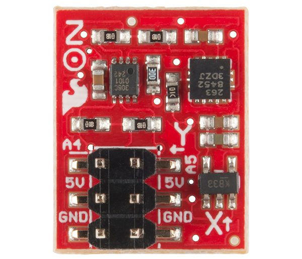
The Accelerometer sensor is an add-on for your RedBot that provides bump and motion detection. The sensor works by measuring acceleration forces on the x, y, and z axis. By measuring the amount of acceleration (or lack there of) your robot can get a better understanding of its movements.
The sensor has a 2x3 unpopulated footprint which connects directly to the RedBot Mainboard via a female header. You can also solder the sensor directly to the headers on the Mainboard if you wish.
RedBot Whisker Bumper
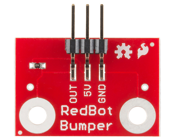
The Whisker Bumper is a very simple sensor comprised of a piece of music wire that closes a contact when bent and a circuit board to interface it to the RedBot. We ship the music wire straight, so you'll have to bend it to suit your application; the example shown above is only one way to do it.
RedBot Buzzer Board
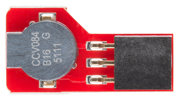
What's the fun of a robot that doesn't make beep-beep noises? We've made the RedBot Buzzer board to fit nicely on any header on the board, so you can integrate noise with your robot either just for fun or as a nice remote feedback function.
There's no special library support needed; just use the tone() family of commands already built into Arduino. One note: you can't use the Buzzer board on pins A6 and A7, as they are analog input-only pins.