Getting Started with the LilyPad MP3 Player
Getting Started with the Default "Trigger" Sketch
The LilyPad MP3 Player comes with a preinstalled sketch (Arduino programs are called sketches) called "Trigger". This sketch will wait for one of the five trigger inputs to be grounded and will then play the corresponding audio file from the micro-SD card. You can sew the LilyPad MP3 Player into your project and use "soft switches" to trigger any sound you want. Best of all, since this sketch comes preinstalled on every LilyPad MP3 Player, you can use it right out of the box, with no programming necessary. Let's get started!
Required Materials
A single-cell (3.7V) Lipo battery (500mAh or above recommended. You can use smaller ones if you reduce the charge rate, see the instructions here).
A 5V FTDI Breakout or cable (to recharge the battery and reprogram the board if desired).
One or two 4 or 8-ohm speakers, surface transducers, or headphones with a 1/8" stereo jack. If you want to connect the LilyPad MP3 Player to an amplifier, see this note.
Conductive thread and sewing supplies, or hook-up wire and soldering tools. (TIP: alligator cables are a great way to quickly test out circuits and programming before committing to needle and thread!)
Some audio files you'd like to play. The LilyPad MP3 Player can play many audio formats, you can see the whole list here.
Instructions
Put up to five audio files onto the micro-SD card. Usually this is done by putting the card into a reader attached to your computer and copying audio files to it. The LilyPad MP3 Player will play a number of audio formats including MP3, WAV, WMA, AAC, MID, etc.
Rename the audio files on the micro-SD card so that the first character of each filename is the number "1" to "5", corresponding to the trigger that you want to play that file. You don't need to change anything else about the filename.
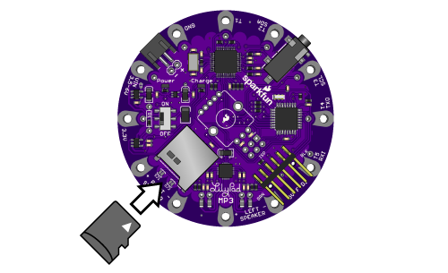
Turn off the LilyPad MP3 Player and plug your micro-SD card into the socket. Push it in until it clicks; if you release it, it will stay seated. To remove it, push again until it clicks, and it will pop out when you release it.
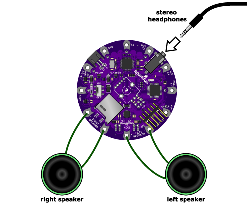
Connect a headphone to the headphone jack, or connect speakers to the left and right speaker terminals. (Note that when anything is plugged into the headphone jack, the speakers are disabled. This behavior can be changed if desired).
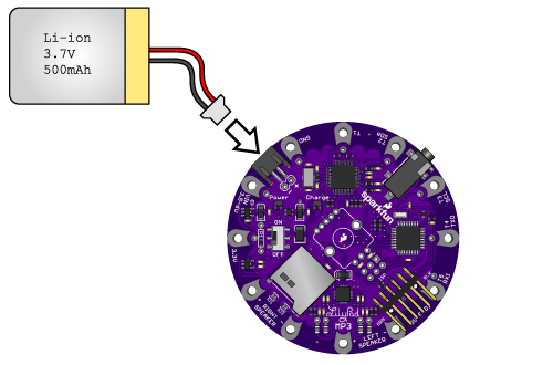
Plug a 3.7V single-cell Lipo battery into the JST connector. Note that a FTDI USB connection will not provide enough power to run the board, so a battery or other external power source is required.
Move the power switch to ON. The red LED should light up.
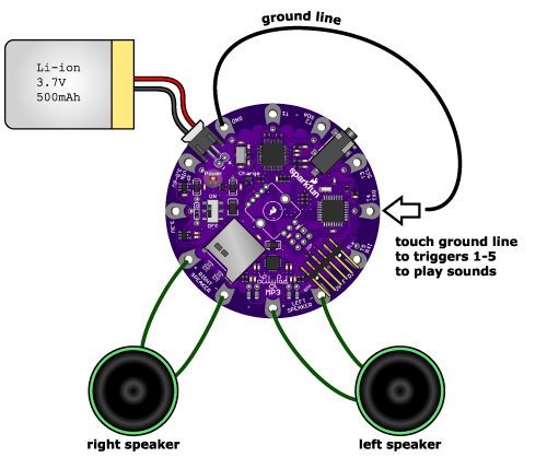
Wait a few seconds for the software to start up. Now, momentarily, connect the ground sew tap (marked GND) to one of the trigger terminals (marked T1 through T5). The audio file associated with that terminal should play through the speakers / headphone. If you don't hear anything, see the troubleshooting page.
To charge the battery or reprogram the board, connect a 5 volt FTDI board to the FTDI header. The yellow LED will light up while the battery is charging, and go out when it's full. To reprogram the board, see the instructions here.
Have fun!
Now that you know how the trigger sketch works, it's time to think about what you'll do with it.
Tips
The Trigger sketch has several software settings within it that control whether triggers can restart an already playing clip, send debugging information to the serial monitor window, etc. You can easily change these settings if desired, or make any other changes you wish to the sketch, by using the free Arduino programming environment. See the programming page for more information.


