Getting Started with the GeoFence
Hardware Overview
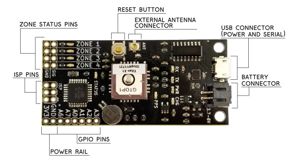
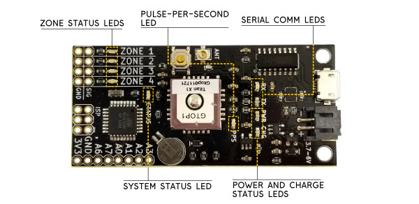
Let's get familiar with the hardware on the GeoFence. We'll break it down into two categories: The connectors and the LED indicators.
Connectors
Zone Status Pins
These pins each correspond to a numbered boundary in the software. The row of pins labeled SIG are the signal pins and the row beside them are ground pins. Whenever the board is outside of a defined zone, that zone's pin will remain logic LOW. As long as the board is inside of a defined zone, that zone's pin will remain logic HIGH.
Reset Button
This button is tied to the reset line on the microcontroller and will restart the board.
External Antenna Connector
The Titan X1 GPS module has a good built-in antenna but if you embed this board into an enclosure where the antenna can't pick up anymore satellites you can connect a 3V external antenna to this U.FL connector (we sell a U.FL to SMA cable if you need one). The GPS module will automatically select an external antenna if one is present.
USB Connector
The Micro-B connector is used to load zone configurations onto the board as well as to provide power for charging a connected lithium ion battery. Since the on-board ATmega328 is carrying the Arduino bootloader, you can also use this USB connector to push new firmware to the board. Select the Arduino Pro Mini with 3.3V/8MHz when loading new firmware.
Battery Connector
The GeoFence has a built-in battery charger and voltage regulator so you can easily power it on the go. Any of our single-cell lithium ion batteries will work but I personally like the 1Ah battery because it's about the same size as the board.
GPIO Pins
These are excess pins broken out from the ATmega328P that you can use if you write your own firmware. The production firmware for the GeoFence uses the A0 pin as the System Status pin which goes to logic HIGH when the system has a valid lock. This pin makes it possible for outside systems to know whether the zone status pins are showing the most up-to-date information.
Power Rail
The 3V3 and GND connections here allow the board to be powered from an outside regulated 3.3V source. Because this pin is connected directly to the 3.3V rail on the board, it will also source 3.3V whenever a battery is connected or the board is plugged into USB power.
LED Indicators
Zone Status LEDs
These LEDs reflect the state of the zone status pins. They come in handy for testing as you can tell at a glance whether or not the board is in a particular zone boundary.
Pulse-Per-Second LED
This LED is connected to the PPS (Pulse Per Second) output of the Titan X1 GPS module. The PPS output goes logic HIGH for a short duration once per second. This timing signal is a good secondary indicator for whether your GPS module is functioning correctly.
Serial Comms LEDs
These are the same lights that you would find on most Arduino boards. They're connected to the serial communication lines between the USB-Serial bridge and the ATmega328. They're labeled with respect to the microcontroller so RX flashes when the board is receiving data and the TX light flashes when the board is sending data.
Power and Charge Status LEDs
The PWR LED will stay lit as long as the board is powered. The CHG LED represents the charging status of the lithium ion battery if one is connected. If there's no battery connected, this LED will be off. If there is a battery connected, the LED will remain on as long as it's charging. When the battery is full, the LED will turn off again indicating that charging is complete.
System Status LED
This LED will display one of three system status alerts. If the LED is blinking, then the board is running but the GPS module is waiting to get a lock. If the LED is solid then the GPS has a lock, valid data is coming in and the board is checking zones. If the status LED stays off, there are no zones programmed into the board and no zone tests will be performed.

