Getting Started with the AutoDriver - v13
 SFUptownMaker
Introduction
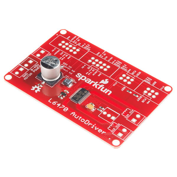
The AutoDriver board is based on the STMicro L6470 dSPIN stepper motor driver. This powerful chip allows you to control a stepper motor with a voltage from 8-45V at 3Arms over an SPI connection.
Compared to traditional step/direction motor controllers, it offers a number of advantages:
- The L6470 tracks the current position of the motor, so the application level doesn't have to.
- "Fire-and-forget" motion control, which allows the application to continue working while the motor autonomously completes the desired motion.
- Acceleration and deceleration curves without complex software algorithms.
- Microstepping for extra smooth movements.
- Configurable currents for acceleration, deceleration, run, and hold, which give greater control to the user over power consumption.
- SPI interface, which allows for a greater number of motors to be driven from a single processor.
The primary disadvantage of the L6470 is that it requires a great deal more configuration and adds software complexity to your system. This hookup guide will attempt to relieve some of that difficulty.
Differences in v13 of the hardware
Version 13 of the hardware is slightly different to the previous revision. It has been modified to make it easier to daisy-chain multiple boards together with simple 10-conductor ribbon cables for data and 6-conductor ribbon cables for control.
The library has changed as well, although it is possible to use the new library with the old revisions. The main addition to the library is an index parameter which is passed to the class constructor, allowing the user to specify where each Autodriver board is in a chain. Pin and SPI configuration were moved out of the library, as well, allowing for the use of SPI ports other than the main port on devices with more than one SPI port.
Suggested Reading
Before you get started, you may want to look at these other tutorials to get you headed in the right direction:
- SPI - The Serial Peripheral Interface is the means by which the L6470 chip, and therefore the AutoDriver board, communicates with the system master CPU.
- Motors - Understanding stepper motors is important to driving them.
- Installing an Arduino Library - The AutoDriver has an Arduino library; if you don't already know how to install a new library, check out this tutorial to get you pointed in the right direction.
Hardware
The AutoDriver board is designed to be easily integrated into a project, even with multiple boards. Here's a brief tour of the hardware and how to connect it up.
The Board
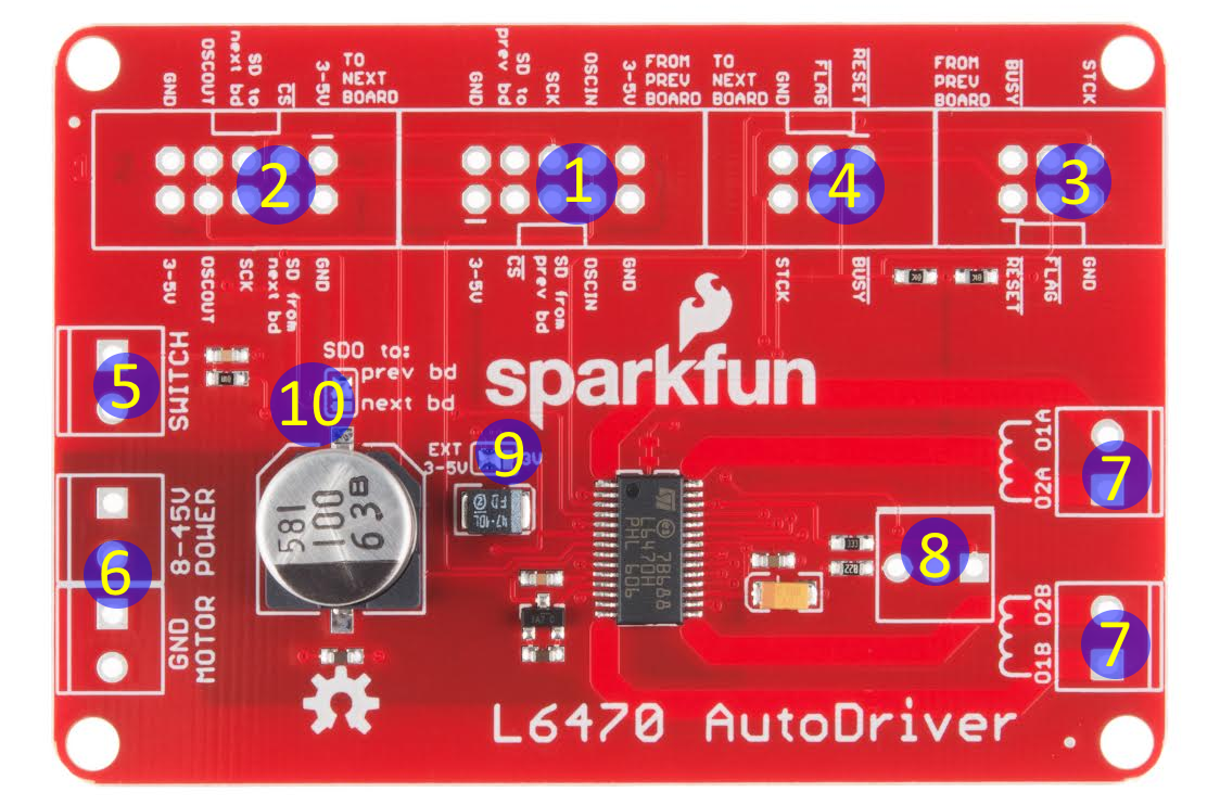
As you can see above, there are several connectors on the board. Let's take them one at a time:
- Communications in - where the SPI, clock, and logic level power enter the board. That can be either from the system CPU or from a prior AutoDriver board. By default, the AutoDriver expects a power supply input here, but that power supply is not the supply to the motors and should not exceed 5V. Designed for a 2x5 .1" shrouded connector, and to be connected by a 2x5 ribbon cable.
- Communications out - SPI, clock, and logic power out to the next AutoDriver. Designed for a 2x5 .1" shrouded connector, and to be connected by a 2x5 ribbon cable.
- Control signal in - metasignals for input and output to and from the AutoDriver. Chip select, optional step clock, and reset inputs come in here, and open-drain busy and error flag signals go back to the previous board. Designed for a 2x3 .1" shrouded header and to be connected by a 2x3 ribbon cable.
- Control signal out - Passes the common control signals on to the next AutoDriver. All pins on this header are common to the same pins on the control signal input header. Designed for a 2x3 .1" shrouded header and to be connected by a 2x3 ribbon cable.
- Switch input - the L6470 can accept input from switches to provide for a hard-stop limit switch or a configurable user interrupt. We'll cover that later. Sized for a 3.5mm screw terminal.
- Power input - two connectors with two terminals each for power and ground to make connecting multiple boards to one power supply easy. This is the motor power input and is sized for a 3.5mm screw terminal. Motor power must be connected in order for the board to respond to commands!
- A and B winding outputs - the L6470 is designed to work with a bipolar stepper motor or a unipolar or universal stepper motor configured as a bipolar. One winding should be connected to each of these terminals, although it doesn't matter which winding connects to which terminal (other than to determine which direction is considered "forward").
- ADC input/potentiometer footprint - this footprint can be populated with a 200k potentiometer to provide for motor supply voltage correction, to ensure a constant drive current across varying supply voltages. Highly optional, but we put the footprint there, just in case.
- Data voltage supply signal - This jumper selects between the external supply on the communication header and the internally generated 3V supply. It is generally assumed that the user will pass the supply voltage across the communication header.
- Data routing jumper - This jumper allows the user to determine where data from this board will be sent: either forward, to the next board in the series, or backward, to the previous board in the series. When multiple Autodriver boards are connected in series, the last board (farthest from the controlling CPU) should be left as default (i.e., 'prev bd' setting) and all others should have the 'next bd' setting selected. If only one board is to be used, 'prev bd' should be selected.
An Example Connection to a RedBoard
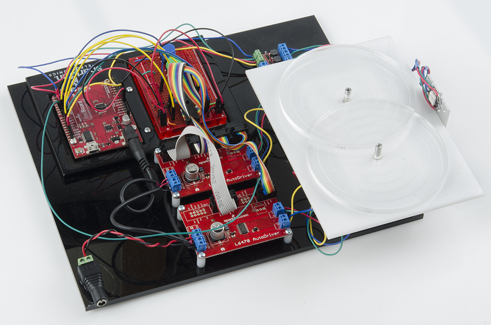
Later in this tutorial, we will show you how to hook up two AutoDriver boards to a RedBoard. For that example, you'll need two AutoDriver Boards along with the following:
Test Hardware Assembly
Here's a step-by-step guide for assembling the parts used for the rest of the guide. If you have your own hardware, feel free to skip this part, but it's not a bad exercise to get you up to speed and make sure that your hardware is in a "known good" state before you begin writing code.
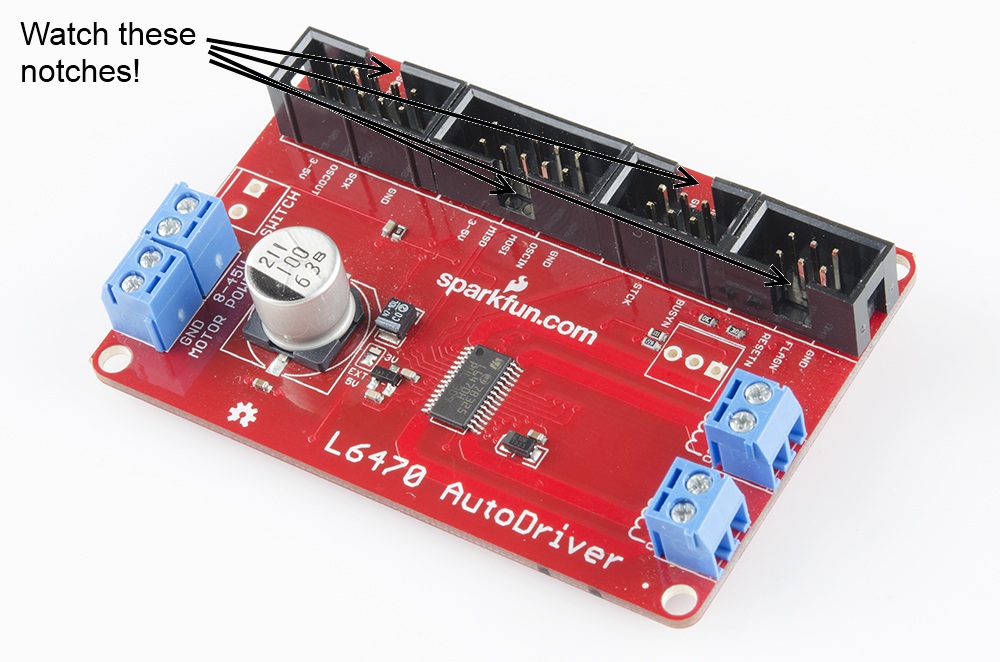
I'm going to take a few liberties with the basics here and assume that you're capable of assembling the RedBoard/Breadboard holder on your own, and that you can put the headers and screw terminal blocks on the AutoDriver boards without help. Pay attention to the orientation of the shrouded headers on the AutoDriver -- if you get them lined up properly, it'll help ensure that the signal routing through the ribbon cables is proper later on. Also note the single pin for the chip select, near the control signal in header. You'll need that later on.
I've also made a base plate to hold my AutoDriver boards in place; mine is fancy laser-cut acrylic, but you can hot glue the boards to a piece of cardboard or even just leave them loose, depending on your personal preferences and tool availability.
Assembling the ribbon cables
You can use pre-assembled ribbon cables, but, as we don't sell pre-assembled 6-conductor cables nor ribbon cables terminated in breadboard-friendly connections, I'm going to cover assembling the necessary cables here.
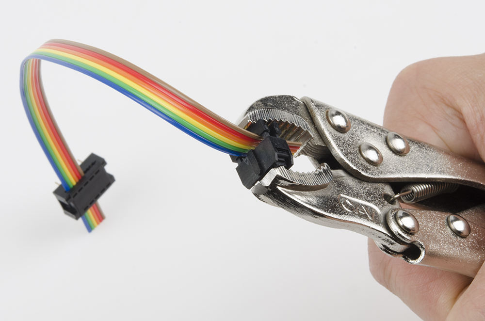
The easiest way to crimp the connectors to the end of the cable is to use a workbench vise; alternatively a pair of channel lock or vise-grip type pliers works well. In a pinch, you can use body weight and any flat surface; it takes quite a lot of pressure to push the connectors shut, however. Don't squeeze too hard, or you'll break the plastic.
Start by cutting your ribbon cable pieces. A pair of scissors works great for this, although it'll be rough on them, so don't use your sewing scissors! To keep our images concise, I'm using really short ribbons for these pictures. Feel free to make yours as long as necessary, although cables longer than a foot or two may cause signal integrity issues, which may affect the operation of your system.
Make sure that there are no little pieces of wire protruding from the end of the ribbon cable -- those can really ruin your day.
Now we need to crimp connectors onto the ends of each cable. We'll start with the breadboard-friendly ends; those are the hardest. Note that we're using the 2x5 connector for both the 10- and 6-conductor cables, since we don't sell a 2x3 breadboard-friendly end.
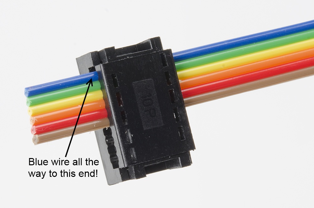
Insert the ribbon cable into the connector as shown below. For the 2x3, make sure that you've got the ribbon cable all the way to the top edge!
Before you apply pressure to crimp the connector closed, you need something to prevent the pins from being smashed in the process. A pencil fits between the pins perfectly.

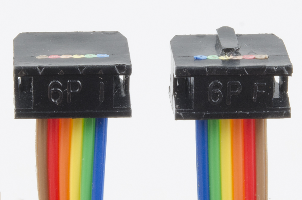
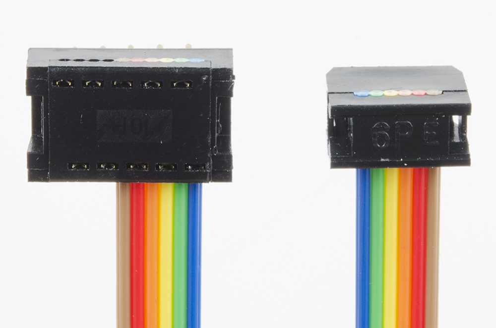
Next, we'll want to crimp on one of the other connectors. See the image below for proper orientation; crimping this in place is much easier because it doesn't have pins to be damaged.
Finally, assemble the additional connectors to the ends of the other ribbon cables, as shown below. Orientation of the connector is important, as the keying on the shrouded headers forces them into the proper orientation only if the cables are assembled right!
Wiring up the stepper motors
As mentioned earlier, there are two screw terminals on the board for connecting the motor. Each one should have one coil of the motor connected to it; if you're not sure of how your stepper motor's wires are connected, you can use a multimeter to figure it out. Two wires connected to the same coil should show a very low resistance (on the order of a few ohms) between them.
Once you've identified the pairs of wires, connect one pair to the 'A' screw terminal and the other to the 'B' screw terminal. The order of the wires isn't terribly important yet, as the order determines the direction in which the motor turns, not whether it turns or not.
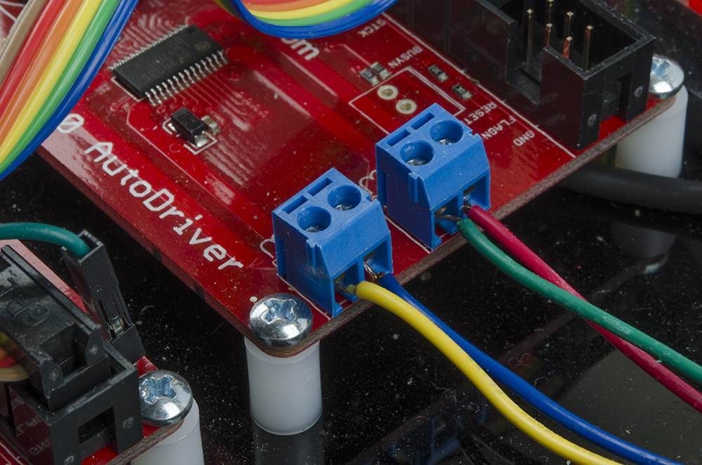
The above picture shows the order I've selected for our medium stepper motors. It's probably a good idea to use the same wire order on both boards, so the relative direction of both motors is the same. If you need the direction to be opposite for the two motors (say, to drive the wheels of a robot), you can simply reverse the order of one pair of wires.
Connecting the boards
If all your ribbon cables are properly assembled, the rest of this should be a snap. Start by inserting the breadboard-friendly ends into the breadboard. You'll be making connections on both sides of the connector, so it helps to pre-bend the ribbon to a right angle with the breadboard.
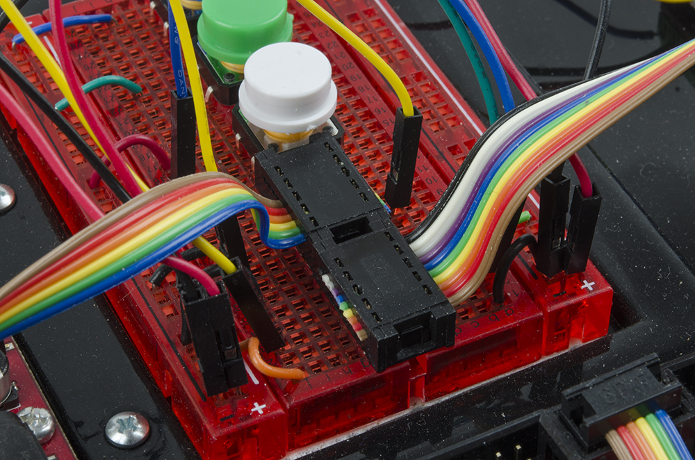
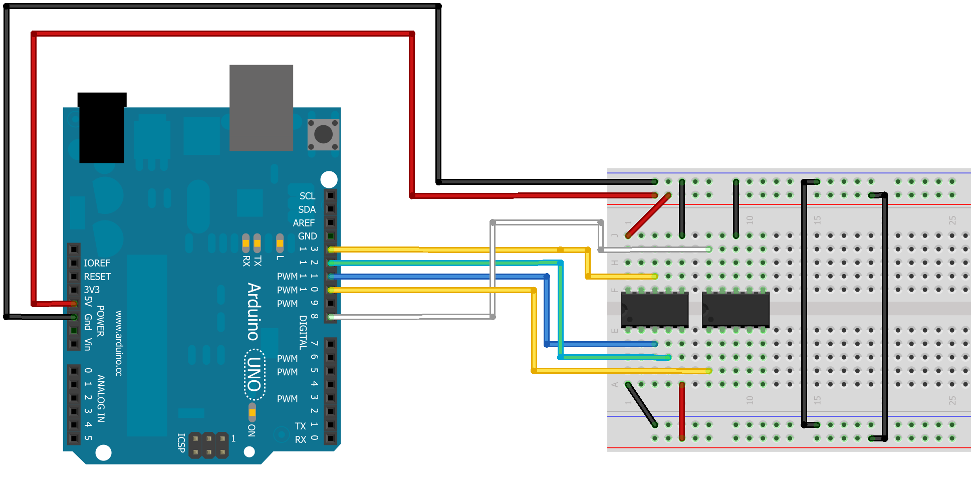
Here's a little wiring diagram of how the connections to the breadboard connectors should be made from the RedBoard or Arduino.
That's the hardest part. Now all you need to do is connect the ribbon cables to the AutoDriver boards.
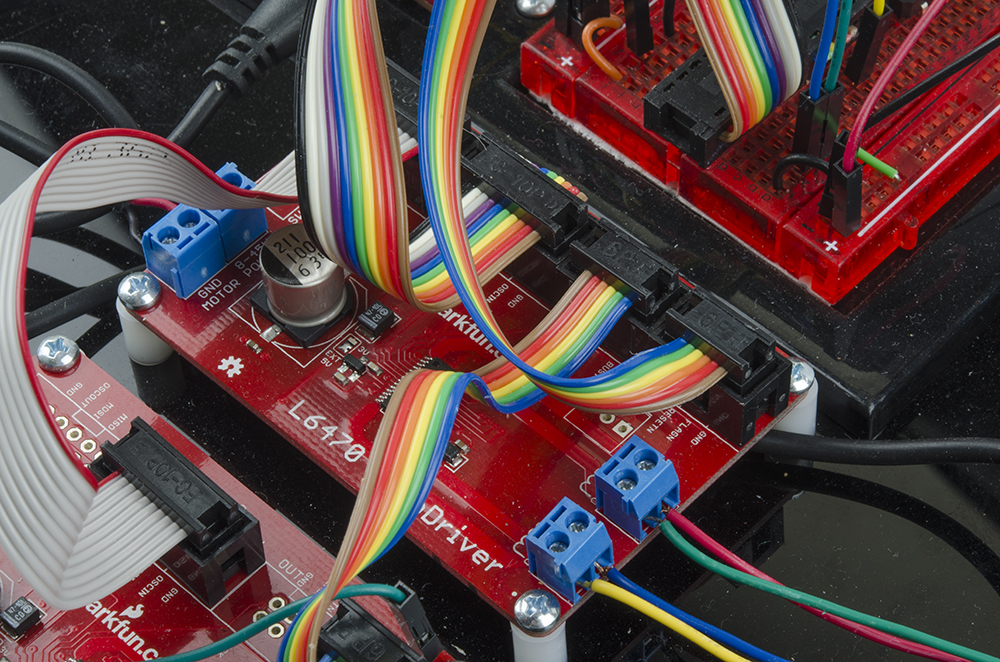
Connecting the Power Supply
Finally, connect up the power. All you need is a four pieces of hookup wire with bared ends. Here's a picture of the power connections all wired up:

It's generally a good idea to hook up the power to the RedBoard and logic circuitry before you power the AutoDrivers; do note that you can't access the AutoDriver boards via SPI until BOTH parts are powered, however.
Arduino Library - Configuration
To make your life a little easier, we've developed a fairly comprehensive library for configuring and controlling the AutoDriver. On this page, we'll go through the various commands in the library and the impact they have on the operation of the AutoDriver board.
As mentioned earlier, the AutoDriver requires more configuration to operate than standard "step/direction" type stepper motor drivers. We've provided functions to make configuring the registers in the L6470 chip much easier than it might otherwise be. Here they are, in no particular order.
Downloading the Library
The library is hosted on GitHub, along with the other design files associated with the AutoDriver board. To install the library and example code to your computer, download this zip file and follow these directions to install the library.
Initialization functions
There are two initialization functions (or "constructors", in C++ class-speke) provided for the AutoDriver library. You must invoke one of them to create an instance of class AutoDriver before you can use the board.
language:cpp
AutoDriver(int boardPos, int CSPin, int resetPin, int busyPin);
AutoDriver(int boardPos, int CSPin, int resetPin);
The two constructors provided allow you to specify which pins the particular AutoDriver boards are connected to, and where the particular board is in the chain of boards. It is assumed that you will connect at least the reset and chip select pins; connecting the busy pin is optional, as the busyCheck() function will check either the pin state or the device's internal register to determine if the AutoDriver is busy or not, depending on whether you use the constructor that initializes a busy pin assignment or not.
This hardware does not initialize the SPI hardware, nor the pin states, for you. For information about how to do that, see the official Arduino SPI library documentation, or any of the code examples that come with the library. It is recommended that you use pin 10 as a chip select pin, since that pin must remain an output at all times in order for the library to function properly (this is a requirement of the SPI peripheral in the chip and cannot be changed).
In order to tell the library which SPI port to use, you'll need to call this function:
language:cpp
SPIPortConnect(SPI *portName);
This allows boards with more than one SPI port to select the one they want to use. For a normal Arduino, though, we expect the function call to look like this:
language:cpp
AutodriverBoardName.SPIPortConnect(&SPI);
See the included examples for more information.
Setting Basic Chip Parameters
There are many different parameters which must be set for the AutoDriver to function properly. These are stored in RAM on the AutoDriver and must be configured after every power cycle or chip reset.
Some of these parameters must be set for the chip to operate successfully; those parameters are described here.
void configSyncPin(byte pinFunc, byte syncSteps);
The BUSY pin on the AutoDriver actually has two possible functions: it can indicate when the board is BUSY (usually indicating that a motion command is underway and has not yet completed) or it can be used to output a sync signal for counting full motor steps with an external device.
There are constants defined for the two parameters: the first can be either BUSY_PIN or SYNC_PIN. If SYNC_PIN is passed, the second parameter should be one of the following:
SYNC_FS_2- two pulses on sync pin per full step of motorSYNC_FS- one pulse per full stepSYNC_XFS- where X can be 2, 4, 8, 16, 32, or 64, and X indicates the number of full steps between pulses on the sync pin
If BUSY_PIN is passed, the second paramater should be zero.
void configStepMode(byte stepMode);
The AutoDriver is capable of microstepping, wherein the output signal is PWMed to create a pseudo-sine wave output which makes the transition from one step to the next less jerky. There are 8 possible microstep options, and defines have been provided for selecting between them:
STEP_FS- Full-step mode; microstepping disabledSTEP_FS_X- Enable microstepping with X microsteps per full step. X can be 2, 4, 8, 16, 32, 64, or 128.
Note that enabling microstepping has no effect on motion commands or sync pulse outputs; it is not possible to move less than one full step. Microstepping simply makes the transition between steps smoother.
void setMaxSpeed(float stepsPerSecond);
Provide an upper limit to the speed the driver will attempt to reach. Attempts to exceed this speed will result in motion being completed at this speed. The value established by this command will also be the value used for motion commands such as goTo() where no speed parameter is provided.
void setMinSpeed(float stepsPerSecond);
The minimum speed is slowest speed the motor will run. If low speed optimization is enabled (see below), minimum speed is automatically zero, and the special low-speed waveform optimization will be used until minimum speed is reached. Defaults to zero.
void setFullSpeed(float stepsPerSecond);
If microstepping is enabled, this parameter sets the speed above which microstepping is disabled and the driver engages full step mode.
void setAcc(float stepsPerSecondPerSecond);
void setDec(float stepsPerSecondPerSecond);
Set the acceleration/deceleration curves to be used. The maximum value for this is 29802; above that, the AutoDriver will not use any curve at all.
void setOCThreshold(byte threshold);
Sets the level at which an overcurrent event occurs. There are 16 different options; all take the format OC_XmA, where X is the limit and can be any of these values: 375, 750, 1125, 1500, 1875, 2250, 2625, 3000, 3375, 3750, 4125, 4500, 4875, 5250, 5625, or 6000.
void setPWMFreq(int divisor, int multiplier);
There's a separate internal clock for the PWM frequency used by the chip when microstepping or when KVAL settings (more on these later) call for a reduction in current. This frequency is 31.3kHz (nominal, when using the internal 16MHz clock), and is adjusted by the divisor and multiplier sent to this function. Again, we've created a set of defines for the possible values:
- For divisor, define syntax is
PWM_DIV_X, where X can be any value 1-7. - For multiplier, define syntax is
PWM_MUL_X, where X can be 0_625 (for 0.625), 0_75 (for 0.75), 0_875, 1, 1_25, 1_5, 1_75, or 2.
It's a good idea to keep the frequency above 20kHz or so, to avoid annoying those in close proximity to the device, as lower frequencies can cause an audible ring or buzz.
void setSlewRate(int slewRate);
The slew rate is the slope of the voltage change coming out of the driver. There are three options here: 180V/us, 290V/us, and 530V/us. Higher slew rates increase the torque at higher speeds, at the risk of increased electromagnetic emissions, which may or may not matter to you. The defines for this are SR_180V_us, SR_290V_us, SR_530V_us.
void setOCShutdown(int OCShutdown);
By default, the drive transistors in the L6470 chip will shutdown on an overcurrent event to prevent damage to motor and driver. This can be disabled by passing the define OC_SD_DISABLE to this function, and re-enabled by passing OC_SD_ENABLE.
void setOscMode(int oscillatorMode);
This is one of the more important of the basic parameters. By default, the chip will run at 16MHz on its internal oscillator, and that suffices for most applications. However, in a situation where more than one AutoDriver is being used in a circuit, it's best to drive all of the boards from a common clock, so the motors will remain synchronized. That clock source can be either an external clock fed to the first chip and then passed along to subsequent chips, or it can be the internal clock source of the first chip, passed along to later devices. There are rather a lot of possible options here; we've created a verbose set of constants to help you select the right one:
INT_16MHZ- Use the internal 16MHz oscillator, with no output on the OSCOUT line.INT_16MHZ_OSCOUT_2MHZ- Internal 16MHz, 2MHz on OSCOUT. Default.INT_16MHZ_OSCOUT_4MHZ- Internal 16MHz, 4MHz on OSCOUT.INT_16MHZ_OSCOUT_8MHZ- Internal 16MHz, 8MHz on OSCOUT.INT_16MHZ_OSCOUT_16MHZ- Internal 16MHz, 16MHz on OSCOUT. Recommended for the first AutoDriver in a system with more than one AutoDriver.EXT_8MHZ_XTAL_DRIVE- External 8MHz crystal. Not recommended.EXT_16MHZ_XTAL_DRIVE- External 16MHz crystal. Not recommended.EXT_24MHZ_XTAL_DRIVE- External 24MHz crystal. Not recommended.EXT_32MHZ_XTAL_DRIVE- External 32MHz crystal. Not recommended.EXT_8MHZ_OSCOUT_INVERT- 8MHz clock to OSCIN. Inverted OSCIN on OSCOUT.EXT_16MHZ_OSCOUT_INVERT- 16MHz clock to OSCIN. Inverted OSCIN on OSCOUT. Recommended for subsequent boards in a multi-board system.EXT_24MHZ_OSCOUT_INVERT- 24MHz clock to OSCIN. Inverted OSCIN on OSCOUT.EXT_32MHZ_OSCOUT_INVERT- 32MHz clock to OSCIN. Inverted OSCIN on OSCOUT.
Two things of note regarding the osciallator settings: first, if you select an invalid setting (for example, an external crystal in a system with no crystal), the AutoDriver board will stop responding. Because the settings are stored in RAM, however, a reset or power cycle of the chip will restore it to operation, allowing you to change your program to a supported clock mode.
Second, the frequency specified in this is used by the library to convert user-friendly units to units the chip understands. Using any frequency besides 16MHz will result in scale errors when setting speeds in steps per second, acceleration in steps per second per second, etc.
Advanced Chip Parameters
void setVoltageComp(int vsCompMode);
Voltage compensation attempts to keep the motor's behavior consistent across varying supply voltage. This is not as straightforward as it sounds, and users wanting to employ this functionality are urged to consider page 34 of the L6470 datasheet.
The defines to enable or disable this are VS_COMP_ENABLE and VS_COMP_DISABLE.
void setSwitchMode(int switchMode);
The switch input on the AutoDriver mode can be made to do one of two things: hard-stop the motor (for limit switch functionality), or perform user-based functions by exposing the switch mode to the user through an internal register. The constants to select between the modes are SW_HARD_STOP and SW_USER.
void setAccKVAL(byte kvalInput);
void setDecKVAL(byte kvalInput);
void setRunKVAL(byte kvalInput);
void setHoldKVAL(byte kvalInput);
The KVAL settings allow you to impose a global scaling on the current used for the four conditions listed above. The input ranges from 0-255, or 0% to 100% in steps of approximately .4%. This can be a good way to reduce the power consumption of your system if the full torque provided by 100% current operation is not required.
void setLoSpdOpt(boolean enable);
Low-speed optimization attempts to improved the zero-crossing of the driving sine wave at low speeds. When low-speed optimization is enabled (true passed to this function), the value set for minimum speed above becomes the speed at which low-speed optimization is no longer applied. When disabled (default, or false passed to this function), the minimum speed value is the lowest speed the driver will attempt to use.
Arduino Library - Operation
Having covered configuring the board to run, let's talk about the commands that actually cause it to perform operations. One common parameter through all of these commands is dir. Any command which calls for dir can have passed to it either FWD or REV. So long as all of your motors are wired up the same, those values will produce the same rotation in all motors. If you find yourself dissatisfied with the rotational direction produced by the FWD and REV constants, the best course of action is to reverse the order of the wires on ONE winding on the motor in question. That will reverse the direction the motor spins.
Any motion will begin at the value defined by the setMinSpeed() function (unless low-speed optimization is enabled, in which case, the motion starts at 0 steps/s and low-speed optimization is used until MIN_SPEED is reached), and will use both the acceleration and deceleration curve values to reach the final speed.
Basic Operations
void resetDev();
Equivalent to toggling the reset pin, but performed through an internal software register control on the L6470 chip. If you don't want to use a pin for reset, this option is for you. Note that this will reset all the settings to default, so don't do it after you've configured the part!
void busyCheck();
Returns a 1 if the board is "busy", i.e., executing a motion command, or a 0 if not. If the current instance of the AutoDriver board was defined with a busyPin, it checks that pin; otherwise, it reads the internal STATUS register on the board to see if the driver is busy or not.
void run(byte dir, float stepsPerSec);
Turns the motor either FWD or REV at stepsPerSecond rate, forever. The BUSY flag will remain asserted until motion is stopped by either issuing a hard stop or a soft stop.
void move(byte dir, unsigned long numSteps);
Turn the motor FWD or REV by numSteps full steps. numSteps is internally limited to 22 bits and is unsigned. The motor will use the acceleration profile as mentioned above, and the top speed of the motor during the motion will be the speed set with the setMaxSpeed() function.
void softStop();
Stop the motor using the value set in the setDec() function. Motor will come to a nice, gentle halt.
void hardStop();
Stop the motor with "infinite" deceleration. Motor will lurch to a very rapid grinding halt. Good for emergency stops.
void softHiZ();
Execute a soft stop, then put the motor drivers into a high-impedance state where no current flows through the windings. Note that this means the motor will turn freely!
void hardHiZ()
Execute a hard stop, followed by setting the drivers to high-impedance.
Position Operations
There are two registers in the L6470 which can be used for absolute position tracking and motion commands: ABS_POS and MARK. These functions use those registers to provide for motion based on the current and desired position of the motor, measured in steps.
long getPos();
The ABS_POS register in the L6470 chip on the AutoDriver contains a 22-bit signed value (-2097152 to 2097151 steps) tracking the position of the motor. This register starts at 0 on power up or reset. getPos() returns the current value of that register. It is automatically incremented during moves of FWD direction, and decremented during moves of REV direction.
void resetPos();
Zero out the ABS_POS register, resetting home to the current location.
void setMark(long newMark)
Create a new MARK, which can be used as a shortcut for some motion commands. The value in MARK can also be automatically set by some events (such as activity on the switch input), if the device is configured properly. Same limits as set forth in the getPos() function above.
void setPos(long newPos)
Set the current position to a new, arbitrary value. Same limits as set forth in the getPos() function above.
void goTo(long pos)
From the current position, move in the shortest possible direction to the position passed by the user. Same limits as set forth in the getPos() function above.
void goToDir(byte dir, long pos);
Similar to goTo(), but with a specified direction. Same limits as set forth in the getPos() function above.
void goHome();
Similar to goTo(0) but requires less time to send via SPI. If a direction is required, use goToDir() instead.
Advanced motion operations
void stepClock(byte dir);
Put the device in a "step-per-pulse" mode, where pulses on the STCK line will cause the motor to move one step in the direction indicated by dir. The ABS_POS register will update, and microstepping will be used to move the motor.
void goUntil(byte action, byte dir, float stepsPerSec);
Start the motor moving, according to the acceleration profile, either FWD or REV, at stepsPerSec rate, until a switch even occurs. When the switch event occurs, one of two things happens, based on the value passed to action: if RESET_ABSPOS is sent to action, the ABS_POS register is reset to zero. If COPY_ABSPOS is sent, the ABS_POS register is copied into the MARK register.
Either way, once the signal is received, either a hard stop or a soft stop will occur. The mode is determined by the setSwitchMode() function: passing SW_HARD_STOP to setSwitchMode() results in a hardstop, while passing SW_USER results in a soft stop.
void releaseSw(byte action, byte dir);
Move the motor at minimum speed until the switch is released, then hard stop and perform action in the same manner as goUntil() (i.e., copy ABS_POS into MARK or reset ABS_POS).
Parameter Access
Because we understand that you may want to do things the hard way, we've included two extra functions which provide full access to the parameter registers documented in the datasheet.
void setParam(byte param, unsigned long value);
unsigned long getParam(byte param);
Both can be used to arbitrarily read and write the exact contents of the registers in the datasheet. Names for the registers as described in the datasheet have been defined for use here, as well.
int getStatus();
Returns the current contents of the STATUS register on the L6470 chip. This is a good communications sanity check because on boot, the value will be 0x2E88.
Single Board Example
Having covered the hardware setup and the use of the library, all that remains is to provide an example sketch for the AutoDriver board.
This sketch allows you to play music by controlling the step rate of your motor. The default song it plays is the first part of "Want You Gone" by Jonathon Coulton. I'm only including the main file and the support functions here; the notes.h and wantYouGone() function files are available on the board's GitHub page.
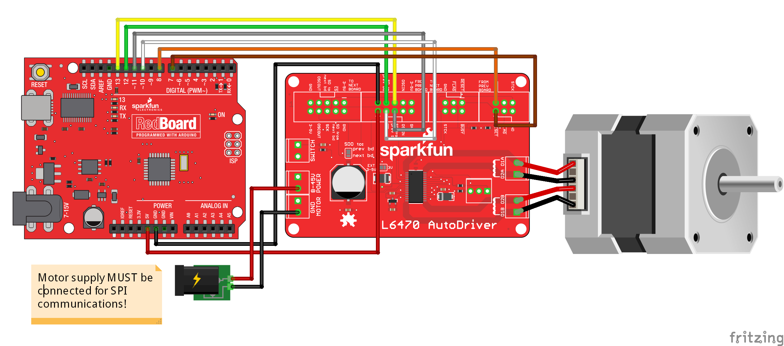
If you skipped over the Test Hardware Assembly page, and just want to hook up an AutoDriver to an Arduino or RedBoard as easily as possible, see the above diagram.
Because of the size and complexity of this sketch, it has been broken into several files. Please be sure you have all the files downloaded!
Setup() and Loop()
language:cpp
#include <SparkFunAutoDriver.h>
#include <SPI.h>
#include "SparkFunnotes.h"

// Test sketch for the L6470 AutoDriver library. This program instantiates one
//  AutoDriver board and uses it to play Jonathon Coulton's "Want You Gone" from
//  the Portal 2 soundtrack. In a more general sense, it adds support for playing
//  music with stepper motors. Not all notes can be played, of course- at too high
//  a steps/sec rate, the motors will slip and dogs and cats will live together.


// Create our AutoDriver instance. The parameters are the position in the chain of
//  boards (with board 0 being located at the end of the chain, farthest from the
//  controlling processor), CS pin, and reset pin.
AutoDriver boardA(0, 10, 7);

void setup()
{
  Serial.begin(9600);
  Serial.println("Hello world");
  // Start by setting up the SPI port and pins. The
  //  Autodriver library does not do this for you!
  pinMode(7, OUTPUT);
  pinMode(MOSI, OUTPUT);
  pinMode(MISO, INPUT);
  pinMode(13, OUTPUT);
  pinMode(10, OUTPUT);
  digitalWrite(10, HIGH);
  digitalWrite(7, LOW);       // This low/high is a reset of the L6470 chip on the
  digitalWrite(7, HIGH);      //  Autodriver board, and is a good thing to do at
                              //  the start of any Autodriver sketch, to be sure
                              //  you're starting the Autodriver from a known state.
  SPI.begin();
  SPI.setDataMode(SPI_MODE3);
  dSPINConfig();
}

// loop() waits for a character- any character- and then plays the song.
void loop()
{
  if (Serial.available() !=0)
  {
    Serial.read();
    Serial.println("Play it!");
    wantYouGone();
    Serial.println("Done playing!");
  }
}
In the main file, you can see that there's not much going on. We initiate one AutoDriver board (as befits our hardware test setup described earlier), call a configuration function, initialize our SPI port and pins, then wait around for a user to request us to play the music.
Support Functions
// Support functions.

#define NOTE_DIVISOR 2  // My cheesy way of reducing the note frequencies to a range
                        //  that doesn't cause the motor to slip. I *could* rewrite
                        //  the wantYouGone() function to change the notes, but that
                        //  would be a lot of work.

int stepDir = 1;        // Direction flipping bit. Rather than all going one way,
                        //  they change directions. It looks cooler.

// To play a note, we start the motor spinning at the note's frequency in steps/s.
//  The run() function automagically calculates the appropriate value to feed to the
//  dSPIN part based on the desired steps/s.
void playNote(int note, int duration)
{
  if (stepDir == 1)  boardA.run(FWD, note/NOTE_DIVISOR);
  else               boardA.run(REV, note/NOTE_DIVISOR);
  delay(duration);
  stepDir*=-1;
  boardA.softStop();
  while (boardA.busyCheck());
}

// This is the configuration function for the two dSPIN parts. Read the inline
//  comments for more info.
void dSPINConfig(void)
{
  boardA.SPIPortConnect(&SPI);      // Before doing anything else, we need to
                                    //  tell the object which SPI port to use.
                                    //  Some devices may have more than one.

  boardA.configSyncPin(BUSY_PIN, 0);// BUSY pin low during operations;
                                    //  second paramter ignored.
  boardA.configStepMode(STEP_FS);   // 0 microsteps per step
  boardA.setMaxSpeed(10000);        // 10000 steps/s max
  boardA.setFullSpeed(10000);       // microstep below 10000 steps/s
  boardA.setAcc(10000);             // accelerate at 10000 steps/s/s
  boardA.setDec(10000);
  boardA.setSlewRate(SR_530V_us);   // Upping the edge speed increases torque.
  boardA.setOCThreshold(OC_750mA);  // OC threshold 750mA
  boardA.setPWMFreq(PWM_DIV_2, PWM_MUL_2); // 31.25kHz PWM freq
  boardA.setOCShutdown(OC_SD_DISABLE); // don't shutdown on OC
  boardA.setVoltageComp(VS_COMP_DISABLE); // don't compensate for motor V
  boardA.setSwitchMode(SW_USER);    // Switch is not hard stop
  boardA.setOscMode(INT_16MHZ_OSCOUT_16MHZ); // for boardA, we want 16MHz
                                    //  internal osc, 16MHz out.
  boardA.setAccKVAL(128);           // We'll tinker with these later, if needed.
  boardA.setDecKVAL(128);
  boardA.setRunKVAL(128);
  boardA.setHoldKVAL(32);           // This controls the holding current; keep it low.
}
The supportFunctions file has a good example of the settings used to configure the AutoDriver boards for this application, as well as a nice example of using the run() and softStop() functions to control the motion of the motor.
Multiple Board Example
There are some things to change to hook up multiple boards. This page will show you how to connect more than one AutoDriver to a RedBoard.
We're going to use the same sketch we used for the single board example. This sketch allows you to play music by controlling the step rate of your motor. The default song it plays is the first part of "Want You Gone" by Jonathon Coulton. I'm only including the main file and the support functions here; the notes.h and wantYouGone() function files are available on the board's GitHub page.
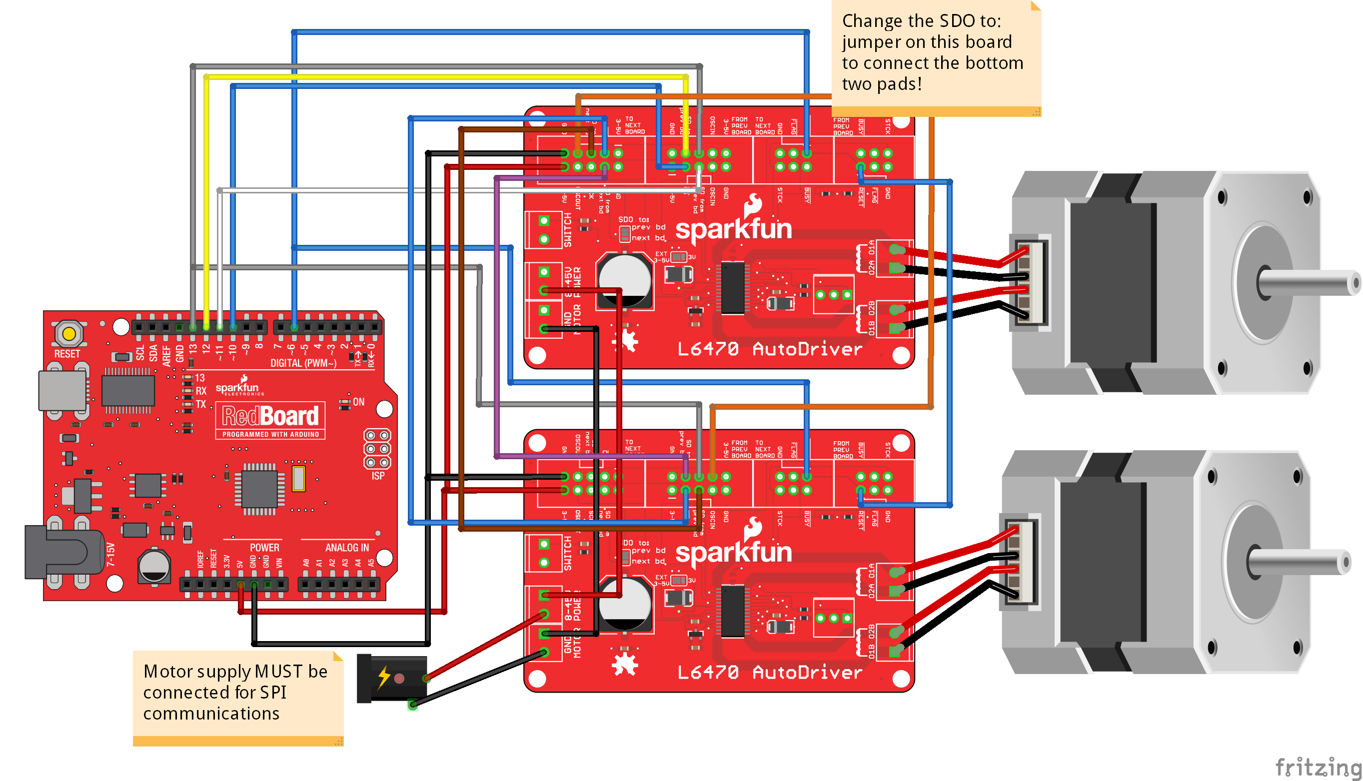
If you're using two boards, note the need to change the 'SDO to:' jumper setting to 'Next bd'! Failure to do so will result in failure of the sketch.
Because of the size and complexity of this sketch, it has been broken into several files. Please be sure you have all the files downloaded!
Setup() and Loop()
language:cpp
#include <SparkFunAutoDriver.h>
#include <SPI.h>
#include "SparkFunnotes.h"

// Test sketch for the L6470 AutoDriver library. This program instantiates three
//  AutoDriver boards and uses them to play Jonathon Coulton's "Want You Gone" from
//  the Portal 2 soundtrack. In a more general sense, it adds support for playing
//  music with stepper motors. Not all notes can be played, of course- at too high
//  a steps/sec rate, the motors will slip and dogs and cats will live together.


// Create our AutoDriver instances. The parameters are the position in the chain of
//  boards (with board 0 being located at the end of the chain, farthest from the
//  controlling processor), CS pin, and reset pin.
AutoDriver boardA(0, 10, 8);
AutoDriver boardB(1, 10, 8);

void setup()
{
  Serial.begin(9600);
  Serial.println("Hello world");
  // Start by setting up the SPI port and pins. The
  //  Autodriver library does not do this for you!
  pinMode(8, OUTPUT);
  pinMode(MOSI, OUTPUT);
  pinMode(MISO, INPUT);
  pinMode(13, OUTPUT);
  pinMode(10, OUTPUT);
  digitalWrite(10, HIGH);
  digitalWrite(8, LOW);       // This low/high is a reset of the L6470 chip on the
  digitalWrite(8, HIGH);      //  Autodriver board, and is a good thing to do at
                              //  the start of any Autodriver sketch, to be sure
                              //  you're starting the Autodriver from a known state.
  SPI.begin();
  SPI.setDataMode(SPI_MODE3);
  dSPINConfig();
}

// loop() waits for a character- any character- and then plays the song.
void loop()
{
  if (Serial.available() !=0)
  {
    Serial.read();
    Serial.println("Play it!");
    wantYouGone();
    Serial.println("Done playing!");
  }
}
In the main file, you can see that there's not much going on. We initiate two AutoDriver boards (as befits our hardware test setup described earlier), call a configuration function, initialize our SPI port and pins, then wait around for a user to request us to play the music.
Support Functions
// Support functions.

#define NOTE_DIVISOR 2  // My cheesy way of reducing the note frequencies to a range
                        //  that doesn't cause the motor to slip. I *could* rewrite
                        //  the wantYouGone() function to change the notes, but that
                        //  would be a lot of work.

int stepDir = 1;        // Direction flipping bit. Rather than all going one way,
                        //  they change directions. It looks cooler.

// To play a note, we start the motor spinning at the note's frequency in steps/s.
//  The run() function automagically calculates the appropriate value to feed to the
//  dSPIN part based on the desired steps/s.
void playNote(int note, int duration)
{
  if (stepDir == 1)  boardA.run(FWD, note/NOTE_DIVISOR);
  else               boardA.run(REV, note/NOTE_DIVISOR);
  if (stepDir == 1)  boardB.run(REV, note/NOTE_DIVISOR);
  else               boardB.run(FWD, note/NOTE_DIVISOR);
  delay(duration);
  stepDir*=-1;
  boardA.softStop();
  boardB.softStop();
  while (boardA.busyCheck());
}

// This is the configuration function for the two dSPIN parts. Read the inline
//  comments for more info.
void dSPINConfig(void)
{
  boardA.SPIPortConnect(&SPI);      // Before doing anything else, we need to
  boardB.SPIPortConnect(&SPI);      //  tell the objects which SPI port to use.
                                    //  Some devices may have more than one.

  boardA.configSyncPin(BUSY_PIN, 0);// BUSY pin low during operations;
                                    //  second paramter ignored.
  boardA.configStepMode(STEP_FS);   // 0 microsteps per step
  boardA.setMaxSpeed(10000);        // 10000 steps/s max
  boardA.setFullSpeed(10000);       // microstep below 10000 steps/s
  boardA.setAcc(10000);             // accelerate at 10000 steps/s/s
  boardA.setDec(10000);
  boardA.setSlewRate(SR_530V_us);   // Upping the edge speed increases torque.
  boardA.setOCThreshold(OC_750mA);  // OC threshold 750mA
  boardA.setPWMFreq(PWM_DIV_2, PWM_MUL_2); // 31.25kHz PWM freq
  boardA.setOCShutdown(OC_SD_DISABLE); // don't shutdown on OC
  boardA.setVoltageComp(VS_COMP_DISABLE); // don't compensate for motor V
  boardA.setSwitchMode(SW_USER);    // Switch is not hard stop
  boardA.setOscMode(EXT_16MHZ_OSCOUT_INVERT); // for boardA, we want 16MHz
                                    //  external osc, 16MHz out. boardB
                                    //  will be the same in all respects
                                    //  but this, as it will generate the
                                    //  clock.
  boardA.setAccKVAL(128);           // We'll tinker with these later, if needed.
  boardA.setDecKVAL(128);
  boardA.setRunKVAL(128);
  boardA.setHoldKVAL(32);           // This controls the holding current; keep it low.

  boardB.configSyncPin(BUSY_PIN, 0);// BUSY pin low during operations;
                                    //  second paramter ignored.
  boardB.configStepMode(STEP_FS);   // 0 microsteps per step
  boardB.setMaxSpeed(10000);        // 10000 steps/s max
  boardB.setFullSpeed(10000);       // microstep below 10000 steps/s
  boardB.setAcc(10000);             // accelerate at 10000 steps/s/s
  boardB.setDec(10000);
  boardB.setSlewRate(SR_530V_us);   // Upping the edge speed increases torque.
  boardB.setOCThreshold(OC_750mA);  // OC threshold 750mA
  boardB.setPWMFreq(PWM_DIV_2, PWM_MUL_2); // 31.25kHz PWM freq
  boardB.setOCShutdown(OC_SD_DISABLE); // don't shutdown on OC
  boardB.setVoltageComp(VS_COMP_DISABLE); // don't compensate for motor V
  boardB.setSwitchMode(SW_USER);    // Switch is not hard stop
  boardB.setOscMode(INT_16MHZ_OSCOUT_16MHZ); // for boardB, we want 16MHz
                                    //  internal osc, 16MHz out. boardA
                                    //  will be the same in all respects
                                    //  but this, as it will bring in and
                                    //  output the clock to keep them
                                    //  voth in phase.
  boardB.setAccKVAL(128);           // We'll tinker with these later, if needed.
  boardB.setDecKVAL(128);
  boardB.setRunKVAL(128);
  boardB.setHoldKVAL(32);           // This controls the holding current; keep it low.
}
The supportFunctions file has a good example of the settings used to configure the AutoDriver boards for this application, as well as a nice example of using the run() and softStop() functions to control the motion of the motor.
Other important items to note: we configure the oscillator on boardB (which, remember, we assigned to position 1) to generate a 16MHz signal on the oscillator out pin, and boardA to use the incoming signal and pass that signal to the next board (although. of course, there is no next board in this system). This will be the case in any chain of Autodriver boards: the highest numbered board should generate the clock, while all lower numbered boards use the input from the previous board and pass a clock signal to the next board. This ensures that all of the boards run at the same clock frequency and are in phase with one another.
Also take note of the SPIPortConnect() functions. You'll pass the same parameter to both of them, as they both use the same SPI port. The library takes care of all the under-the-hood stuff necessary to make sure the right board gets the right signals when you call a function later on.
Resources and Going Further
You should be well on your way to plenty of projects that use stepper motors. Here are some resources to help you on your way.
- stMicro's official L6470 page - Includes some app notes and example code for other environments
- AutoDriver GitHub repository - All the latest board and code files for the product.
Here are some other motor related products and hookup guides for you to check out.