$53.50
MicroPython is an open source interpreter for the Python programming language developed specifically for microcontrollers. In this experiment guide, we will show you how to get started using MicroPython with the popular micro:bit board and our SparkFun Inventor's Kit for micro:bit.
When you're done with this guide, you'll have the know-how to start creating your own projects and experiments with MicroPython for micro:bit!
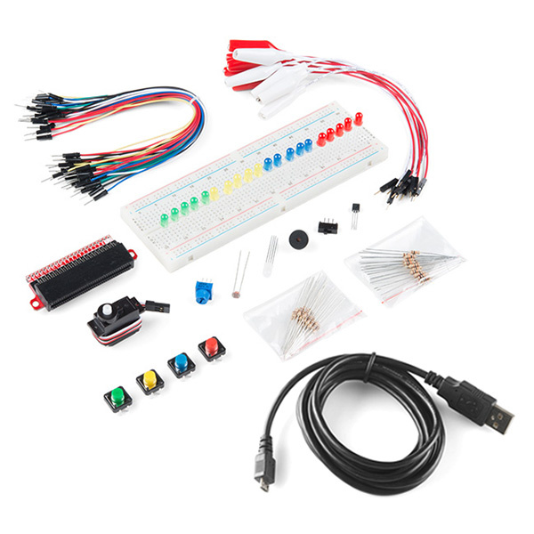
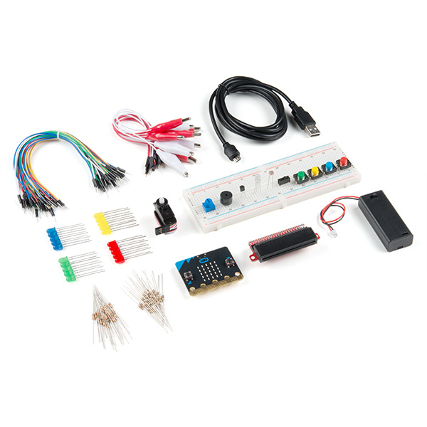
The SparkFun Inventor's Kit (SIK) for micro:bit includes the following:
| SparkFun Inventor's Kit micro:bit SKU |
Revision History |
|---|---|
| KIT-17362, LAB-17363 | - Switch to micro:bit V2. - Switch to Qwiic micro:bit breakout board (with headers). |
| KIT-15228, LAB-15229 | Switch to 2xAAA battery holder with a built-in switch. |
| KIT-14542, LAB-14301 | Initial release. |
What's that? You've already got a micro:bit but still want to follow along? We have options!
If you have never worked with electronics before, we recommend you be somewhat familiar with the concepts in the following tutorials:
All of our experiments and guides are licensed under the Creative Commons Attribution Share-Alike 4.0 Unported License. Feel free to remix and reuse our work. But please, share the love and give us attribution for our hard work!
To view a copy of this license visit this link, or write: Creative Commons, 171 Second Street, Suite 300, San Francisco, CA 94105, USA.
MicroPython is just an interpreter, so it does not include a space to write and edit code. Luckily, there is an editor we can use to write our Python code. Before you get started, you'll need to download Mu. Mu is a simple code editor for beginners that runs on Windows, OSX, Linux and Raspberry Pi.
A major benefit of using MicroPython is the interactive REPL. REPL stands for Read-Evaluate-Print Loop, which is a very long way to say you can execute code live without compiling it first and then uploading it after.
The applications for Python are extensive, and the advantage to using Python over other programming languages include interacting with other languages and platforms, third-party modules, extensive support libraries, user-friendly data structures and, of course, it's open source.
Some known issues with using Mu and micro:bit currently are not being able to import third-party modules [1], not being able to use interrupts, and not having a decent way to map numbers of one range to another. Since importing third-party modules is not supported, we will be copying and pasting the source code in the current Mu MicroPython file. As with learning any new language, Python requires time, patience, self-study and a lot of examples! Keep at it, and we will be here to help you along the way.
To download all of the files needed to follow along with all of the experiments, click the button below from the GitHub repository..
To use MicroPython with the micro:bit, there are a few different options.
You will need the following parts:
If you are conducting this experiment and didn't get the Inventor's Kit, we suggest using these parts:
A "Hello World" on the micro:bit is a little different. On most microcontrollers this program would be executed using a serial terminal. Instead of using a serial terminal, you can interact with your micro:bit using the built-in LED array. So, the "Hello World" for the micro:bit is to draw something using the LED array!
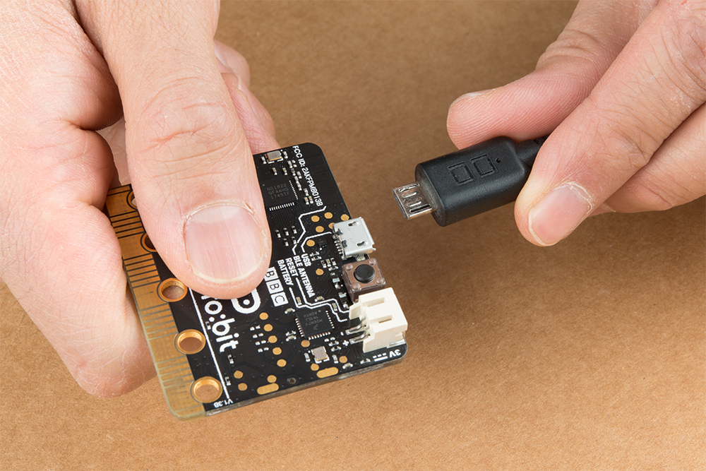
Let's first run the program from the REPL, and then we will build a .py script and upload it to the micro:bit. Open Mu, and make sure your micro:bit is connected to your computer with a USB cable.
To open the REPL, click the icon, and you should see a second window appear at the bottom. Type help() and see what happens.
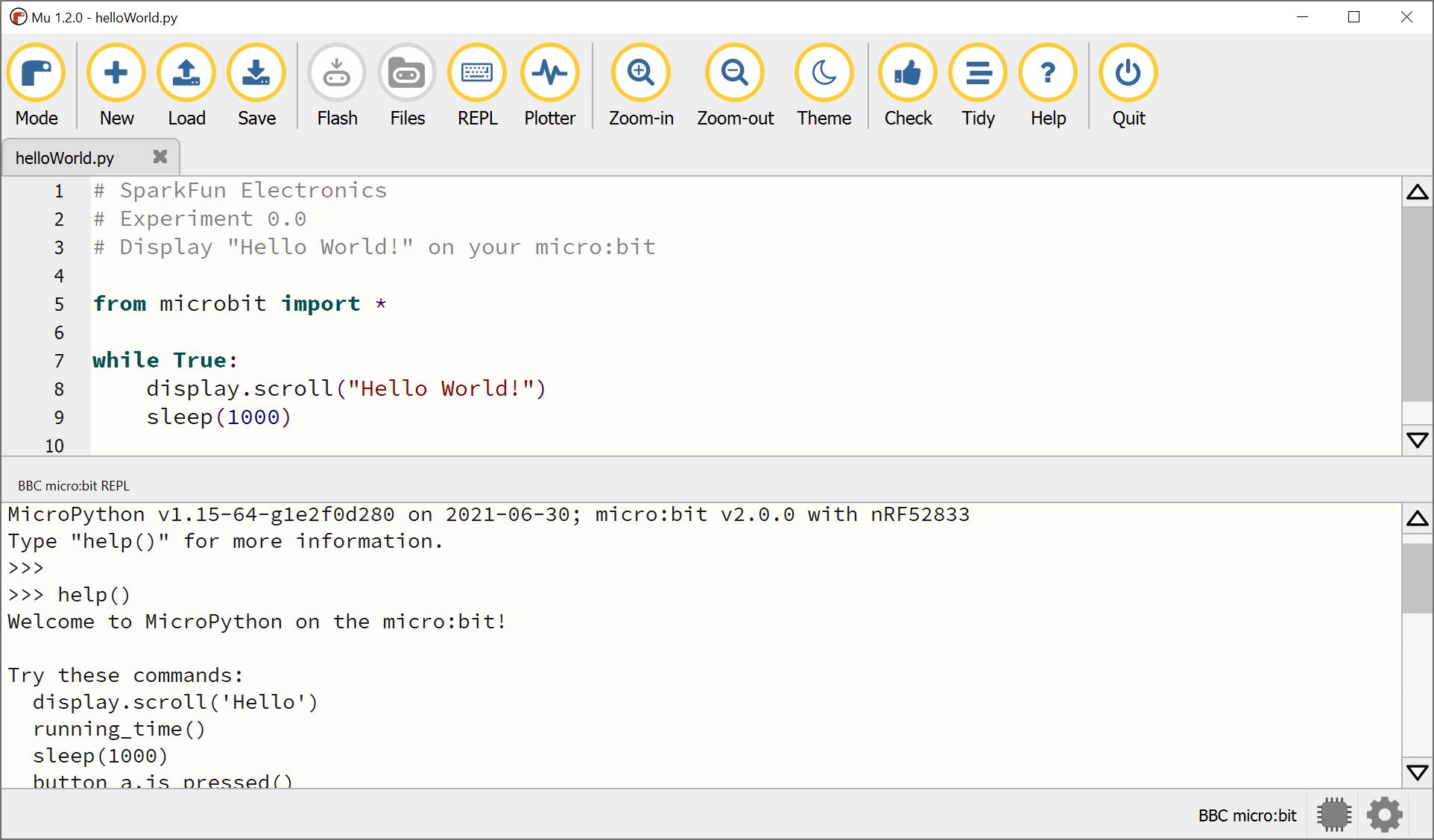
From the REPL, type display.scroll("Hello World") and watch your micro:bit's 5x5 LED array.
language:python
display.scroll("Hello World")
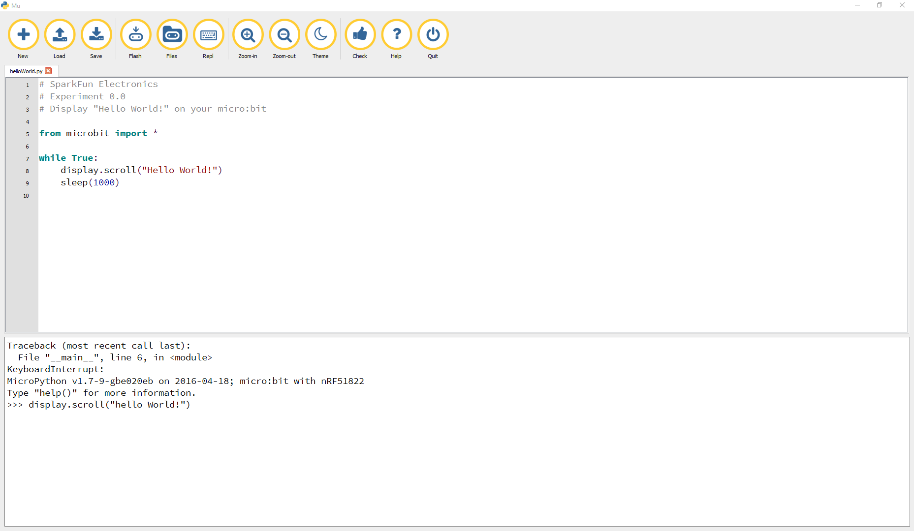
Now close the REPL by clicking the REPL icon!
For the first MicroPython script, we are going to cover how to add comments, how to import a module, and how to create a loop that will run forever.
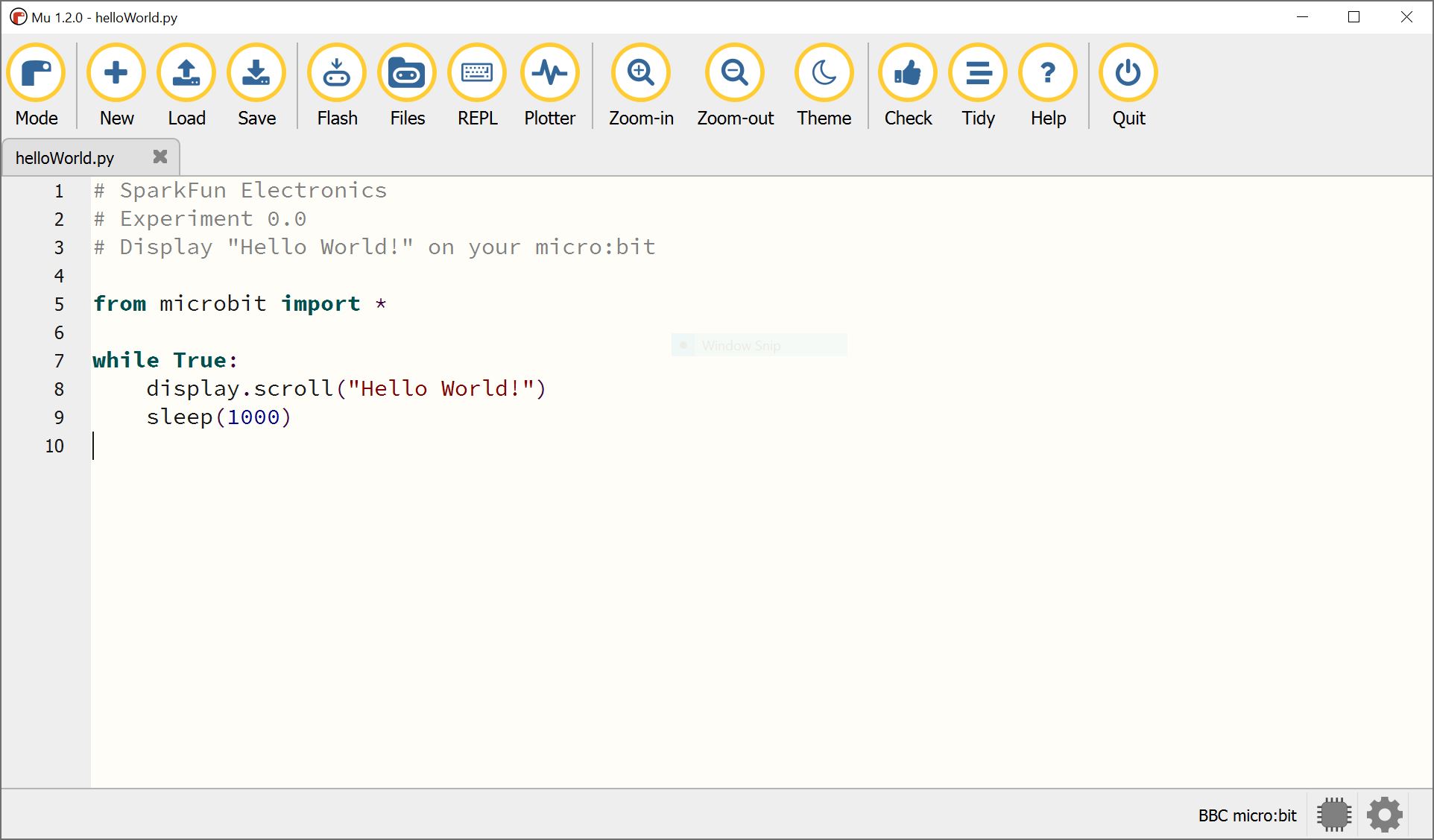
Type (or copy) the program into your Mu editor, or download all the programs from this GitHub Repository and open the Ex0_0_helloWorld.py program.
language:python
# SparkFun Electronics
# Experiment 0.0
# Display "Hello World!" on your micro:bit

from microbit import *

while True:
    display.scroll("Hello World!")
    sleep(1000)
At the top of the program (above), you'll see three lines of comments. Comments are created by using the # sign and one space. You can access modules by using from and import. These words tell the interpreter which classes to import from which modules. In this case, we are importing everything from micro:bit.
The line while True: creates a forever loop in Python so that the program can continue to run the example. The colon is how Python blocks code similar to the way Arduino (another type of text based coding language) uses a set of curly brackets. Everything indented under a colon will execute as a block of code. In this case, we display text and add a small one second delay. The delay is useful to add in programs to process data or initializing IC chips, or for users to reading or viewing data. Just make sure to not make the delay too big as this can make your program run slow from the long pauses.
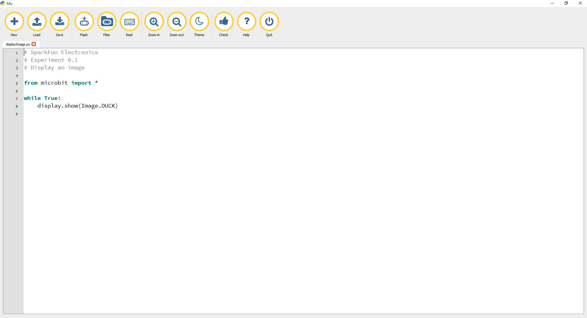
Let's display an image next instead of text. Type (or copy) the program into your Mu editor, or download all the programs from this GitHub Repository and open the Ex0_1_displayImage.py program. Save it, then click the Flash icon to program your micro:bit.
language:python
# SparkFun Electronics
# Experiment 0.1
# Display an image

from microbit import *
while True:
    display.show(Image.DUCK)
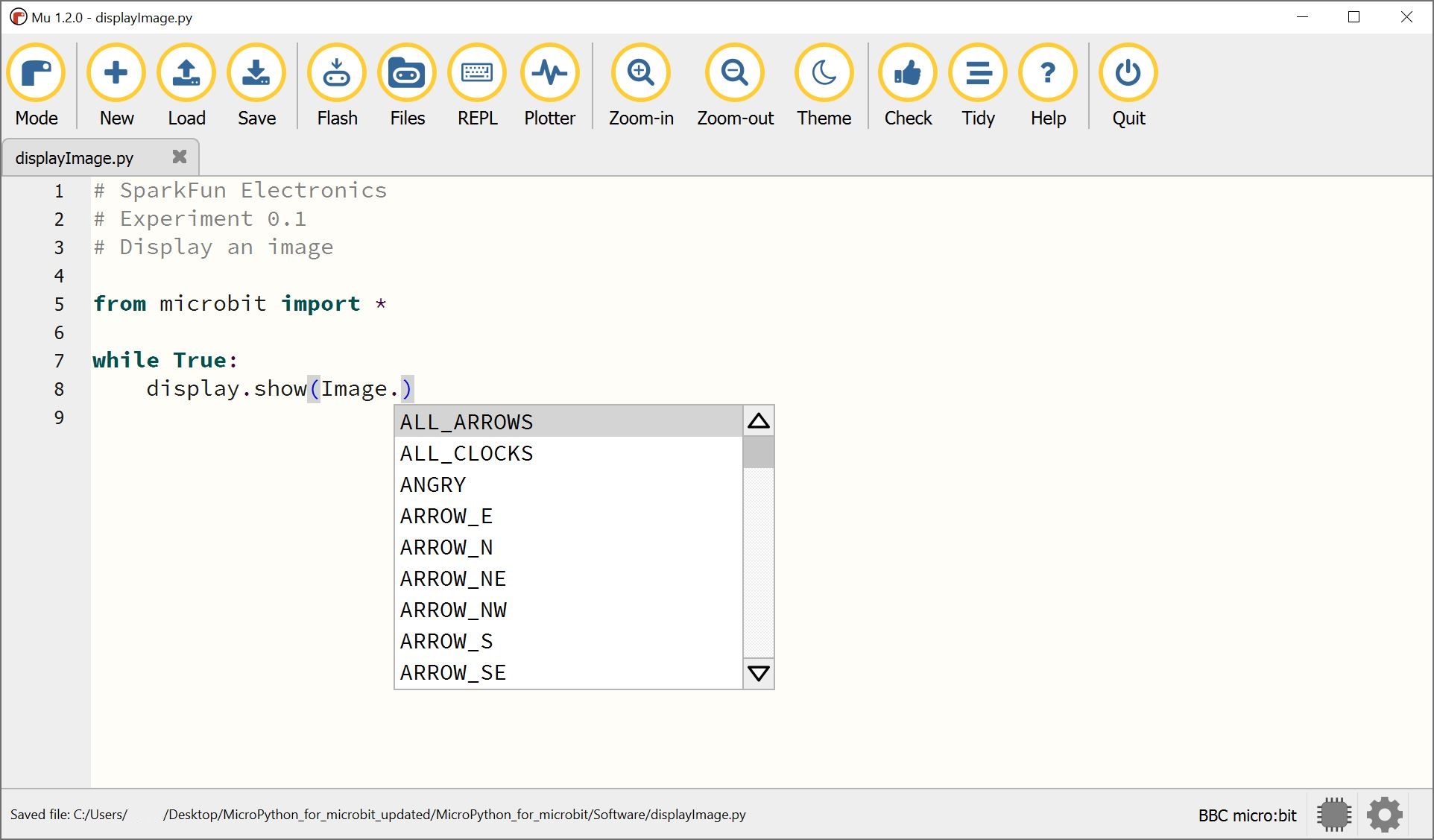
When typing display.show(Image.), let the helpful info box show you what images come built in.
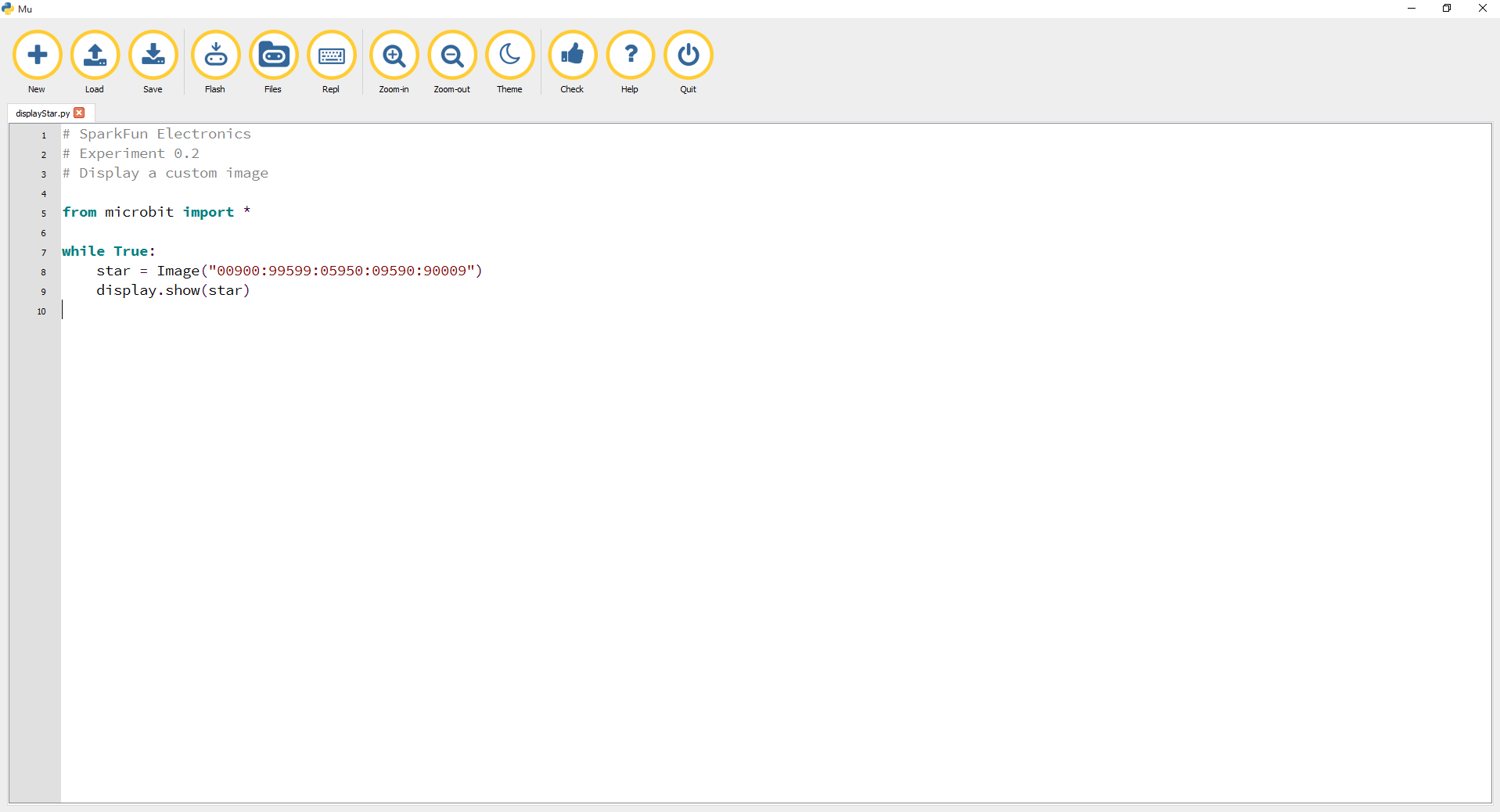
Try to code your own custom image! Below is an example of manually drawing a star. Note that you can control the brightness of an individual LED by adjusting the value between 0 to turn the LED OFF and 9to fully turn on the LED. Each row from the LED matrix is manually controlled inImage("").
language:python
# SparkFun Electronics
# Experiment 0.2
# Display a custom image

from microbit import *
while True:
    star = Image("00900:99599:05950:09590:90009")
    display.show(star)
This is experiment 1 - blinking an LED. We get to the fun stuff: adding hardware and constructing circuits.
You will need the following parts:
If you are conducting this experiment and didn't get the Inventor's Kit, we suggest using these parts:
Before continuing with this experiment, we recommend you be familiar with the concepts in the following tutorial:
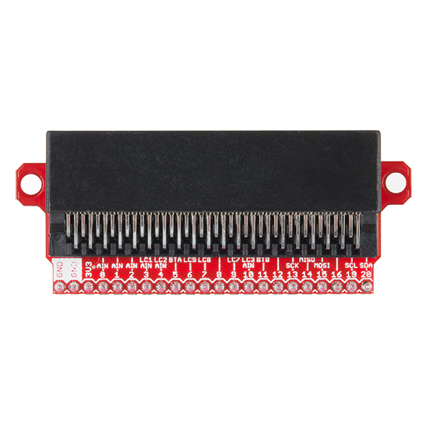
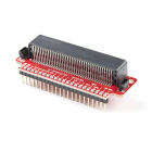
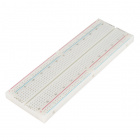
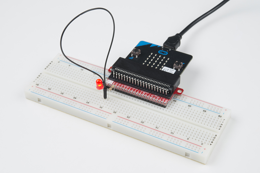
To extend the functionality of the micro:bit beyond what is already on the board, we developed a breadboard adaptor. This adaptor board makes it much easier to use all of the pins available on the micro:bit edge connector in a more user-friendly way. We also broke out ground and VCC (3.3 volts) for your convenience.
The adapter board lines up with the pins of a breadboard. We recommend using a full-sized breadboard with this breakout to give you enough room to prototype circuits on either end of the breadboard.
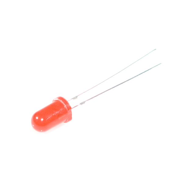
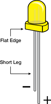
A Light-Emitting Diode (LED) will only let current through in one direction. Think of an LED as a one-way street. When current flows through the LED, it lights up! When you are looking at the LED, you will notice that its legs are different lengths. The long leg, the "anode," is where current enters the LED. This pin should always be connected to the current source. The shorter leg, the "cathode," is the current’s exit. The short leg should always be connected to a pathway to ground.
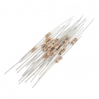
LEDs are finicky when it comes to how much current you apply to them. Too much current can lead to a burnt-out LED. To restrict the amount of current that passes through the LED, we use a resistor in line with the power source and the LED's long leg; this is called a current-limiting resistor. With the micro:bit, you should use a 100 Ohm resistor. We have included a baggy of them in the kit just for this reason!
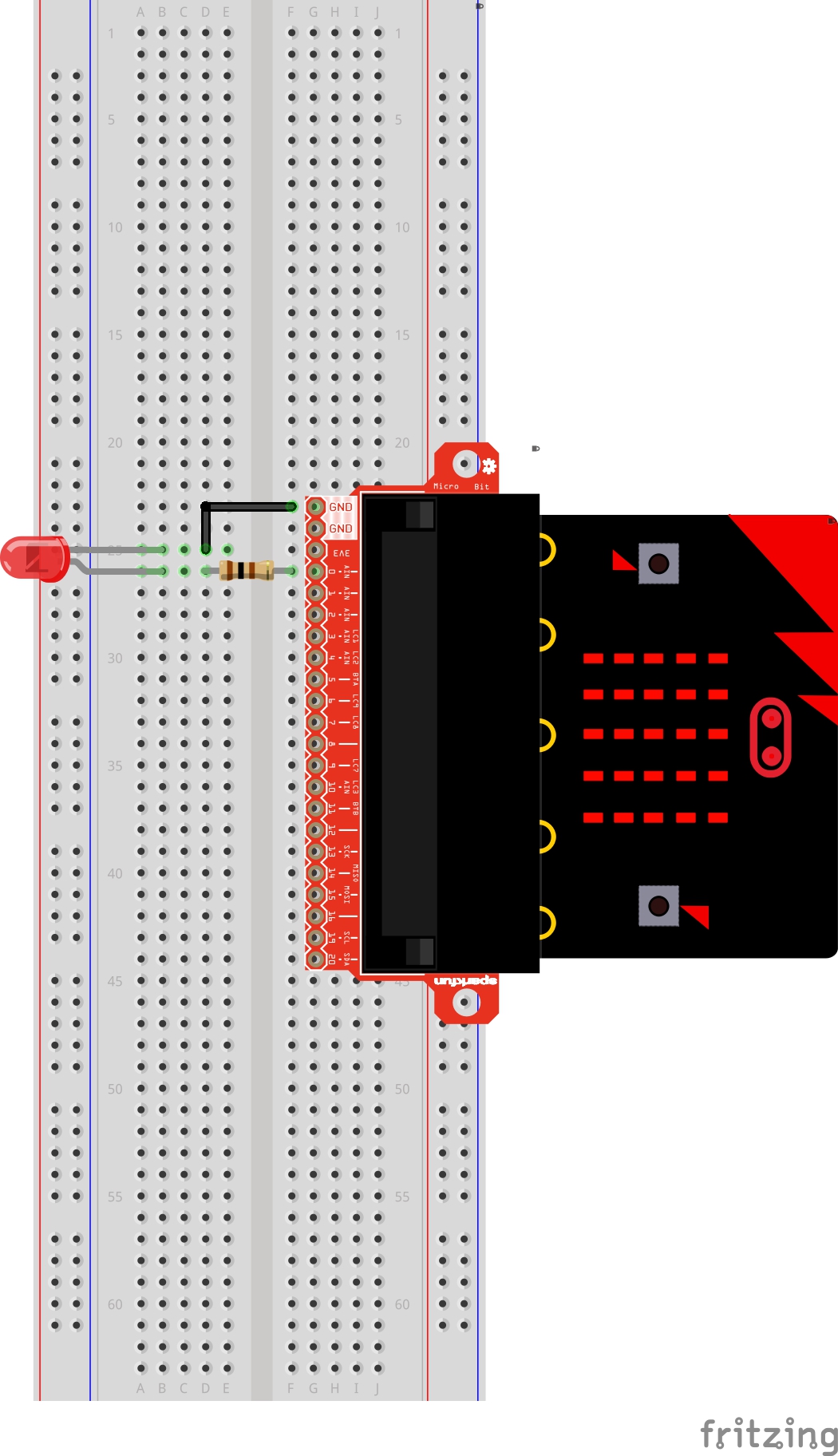
Ready to start hooking everything up? Check out the wiring diagram and hookup table below to see how everything is connected.
| Polarized Components | Pay special attention to the component’s markings indicating how to place it on the breadboard. Polarized components can only be connected to a circuit in one direction. |
Please note: Pay close attention to the LED. The negative side of the LED is the short leg, marked with a flat edge.
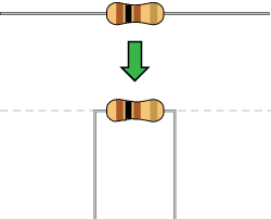
Components like resistors need to have their legs bent into 90° angles in order to correctly fit the breadboard sockets. You can also cut the legs shorter to make them easier to work with on the breadboard.
Let's blink the LED. Type (or copy) the program into your Mu editor, or download all the programs from this GitHub Repository and open the Ex1_blinkLED.py program. Save it, then click the Flash icon to program your micro:bit.
language:python
# SparkFun Electronics
# Experiment 1.0
# Blinking an LED

from microbit import *

while True:
    pin0.write_digital(1)
    sleep(1000)
    pin0.write_digital(0)
    sleep(1000)
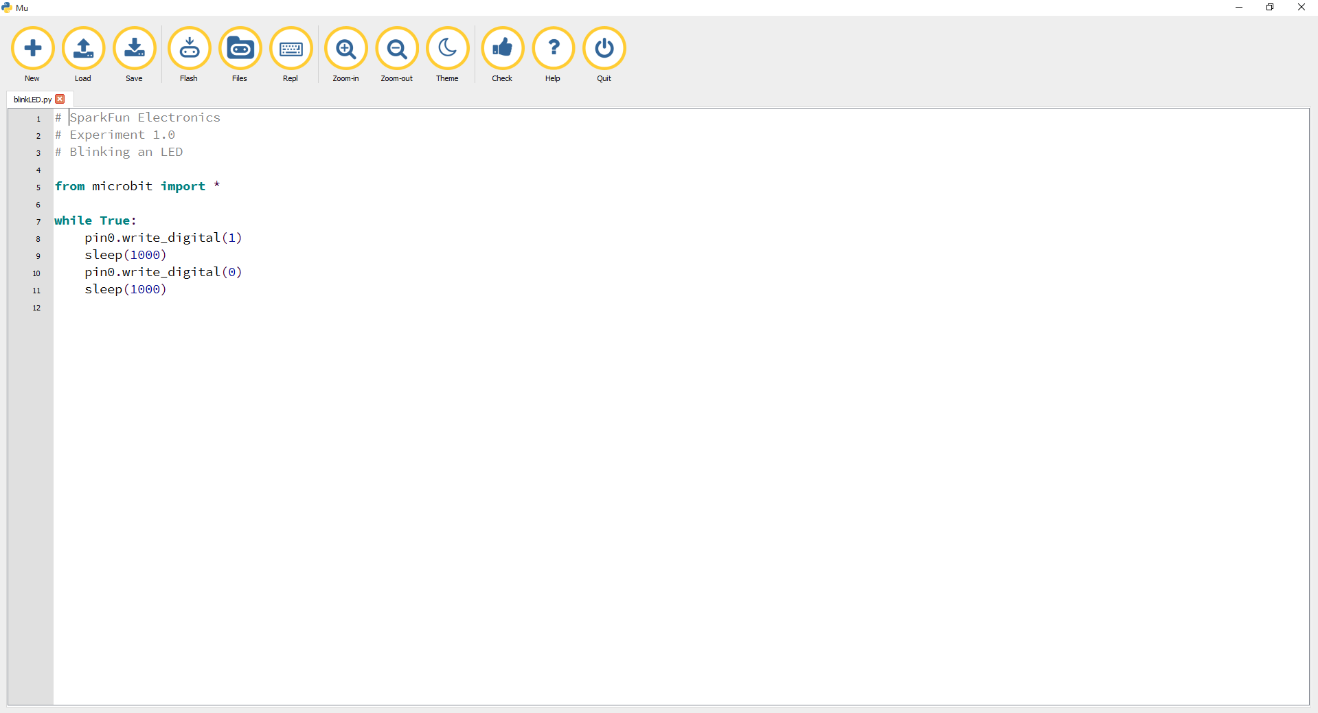
You'll see that is is not much different from the previous experiment except for the lines 8 and 10. pin0.write_digital(1) sends a HIGH value, ON or a voltage of 3.3V to pin 0 on the micro:bit. pin0.write_digital(0) sends LOW value, OFF or 0V to pin 0 of the micro:bit.
You should see your LED blink on and off at 1-second intervals. If it doesn't, make sure you have assembled the circuit correctly and verified and uploaded the code to your board, or see the Troubleshooting section. Change the number in the sleep() and play with the LED blink rate.
Make sure you have it wired correctly and the correct pin to ground. Remember, short pin to ground; long pin to signal.
A broken circuit is no fun. Send us an email, and we will get back to you as soon as we can: techsupport@sparkfun.com
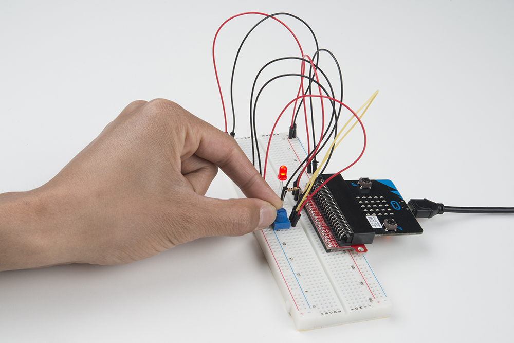
In this circuit you will work with a potentiometer. You will learn how to use a potentiometer to control the brightness of an LED by reading a sensor and storing its 0--1023 value as a variable, then using it as a brightness level for the LED.
You will need the following parts:
If you are conducting this experiment and didn't get the Inventor's Kit, we suggest using these parts:
Before continuing with this experiment, we recommend you be familiar with the concepts in the following tutorial:
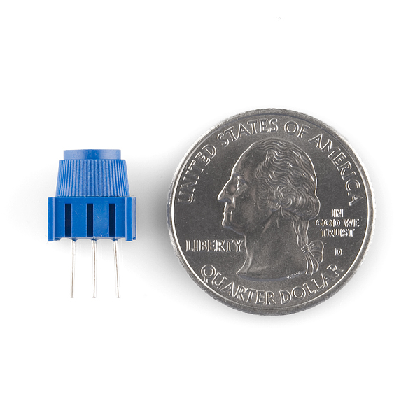
A potentiometer is a resistance-based analog sensor that changes its internal resistance based on the rotation of its knob. The potentiometer has an internal voltage divider enabling you to read the change in voltage on the center pin with a microcontroller (the micro:bit). To hook up the potentiometer, attach the two outside pins to a supply voltage (5V in this circuit) and ground. It doesn’t matter which is connected where, as long as one is connected to power, and the other to ground. The center pin is then connected to an analog input pin so the micro:bit can measure the change in voltage. When you twist the knob, the sensor reading will change!
Ready to start hooking everything up? Check out the wiring diagram and hookup table below to see how everything is connected.
| Polarized Components | Pay special attention to the component’s markings indicating how to place it on the breadboard. Polarized components can only be connected to a circuit in one direction. |
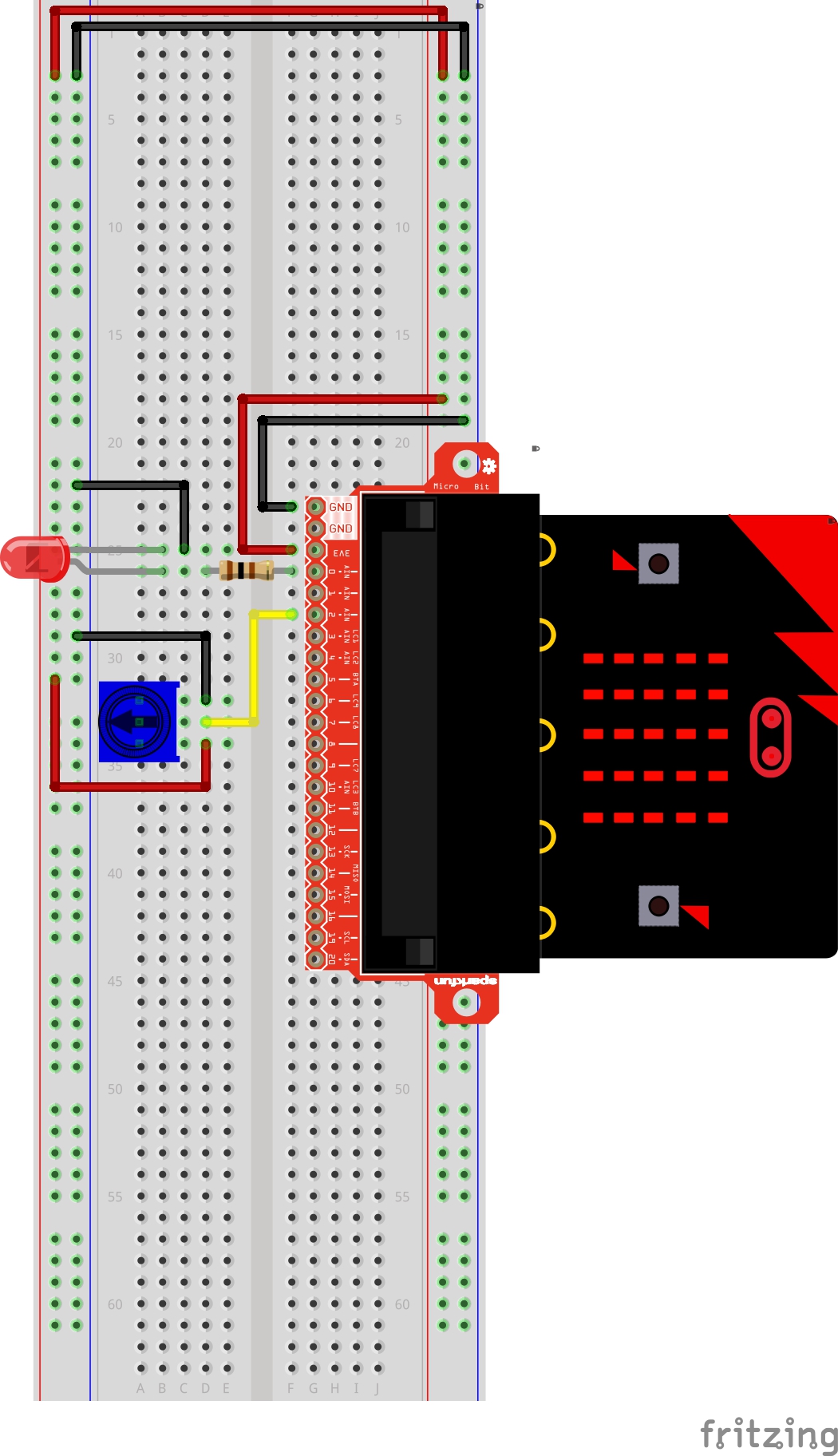
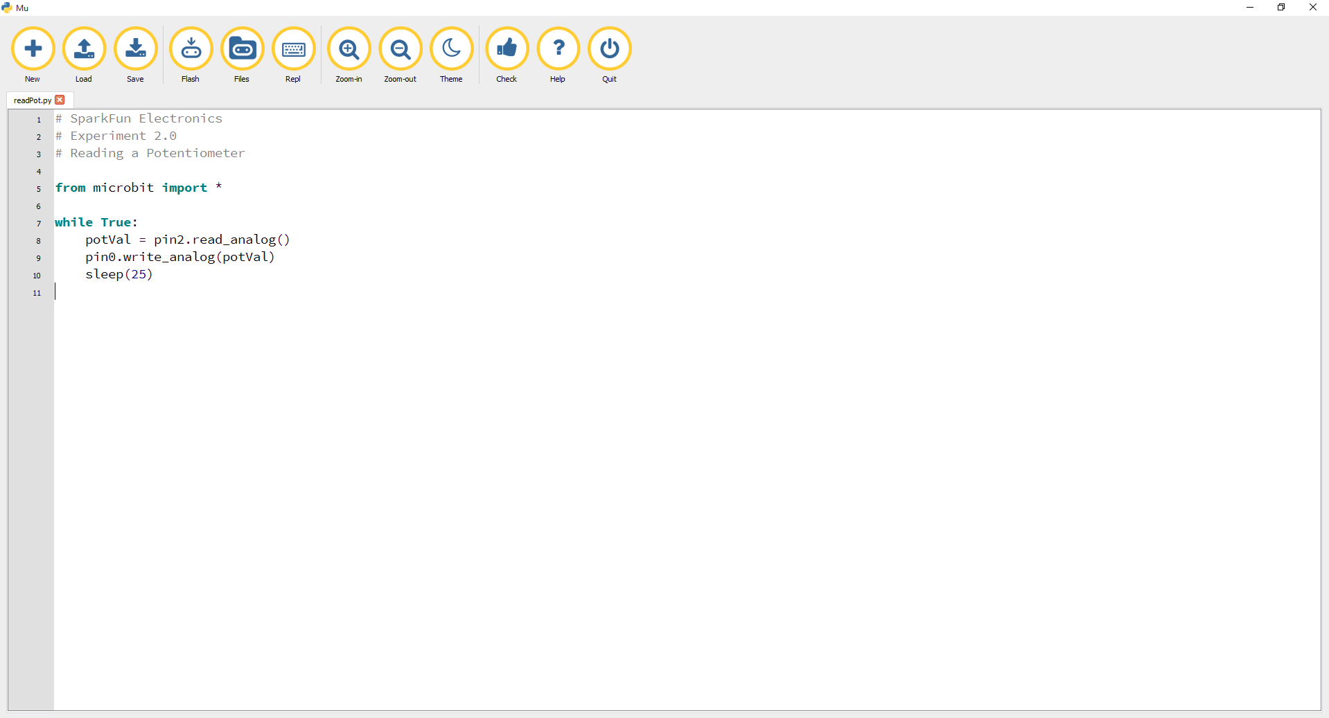
Let's read a potentiometer and control the brightness of an LED. Type (or copy) the program into your Mu editor, or download all the programs from this GitHub Repository and open the Ex2_readPot.py program. Save it, then click the Flash icon to program your micro:bit.
language:python
# SparkFun Electronics
# Experiment 2.0
# Reading a Potentiometer

from microbit import *

while True:
    potVal = pin2.read_analog()
    pin0.write_analog(potVal)
    sleep(25)
In this program you are reading the voltage from the potentiometer, which is 0 to 3.3 volts on pin 2. The micro:bit reads that value as a 10-bit number, which is a value range from 0 to 1023 using the call pin2.read_analog(). We are saving that number to a variable called potVal.
As with the analog read, the analog write deals with a range of values, but instead of reading a pin as an input, the line pin0.write_analog() outputs an analog value to a pin. We see this as a brightness range with this LED, but it could be a tone from a buzzer, a motor speed, etc. We set our analog output to the variable we stored the potentiometer value in.
A “variable” is a placeholder for values that may change in your code. You can create a variable by simply typing a name and setting it equal to what you want. Python is a dynamically typed language. This means the type of variable is determined at runtime. So you do not need to worry about declaring your variable type.
You should twist the potentiometer. You will notice that the LED will get brighter or dimmer based on the position of the potentiometer. If you turn the potentiometer all the way one direction, it will be fully on, and the other end will be fully off.
This is most likely due to a slightly dodgy connection with the potentiometer's pins. This can usually be conquered by holding the potentiometer down or moving the potentiometer circuit somewhere else on your breadboard.
Make sure you haven’t accidentally connected the wiper (center pin), the resistive element in the potentiometer, to a wrong pin!
LEDs will only work in one direction. Double check your connections.
In Experiment 2, you got to use a potentiometer, which varies resistance based on the twisting of a knob and, in turn, changes the voltage being read by the analog input pin. In this circuit you’ll be using a photoresistor, which changes resistance based on how much light the sensor receives. You will read the light value of the room and have an LED turn on if it is dark and turn off if it is bright. That's right; you are going to build a night-light!
You will need the following parts:
If you are conducting this experiment and didn't get the Inventor's Kit, we suggest using these parts:
Before continuing with this experiment, we recommend you be familiar with the concepts in the following tutorial:
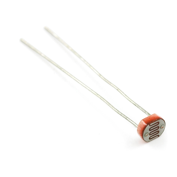
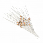
The photoresistor changes its resistance based on the light to which it is exposed. To use this with the micro:bit, you will need to build a voltage divider with a 10k ohm resistor, as shown in the wiring diagram for this experiment. The micro:bit cannot read a change in resistance, only a change in voltage. A voltage divider allows you to translate a change in resistance to a corresponding voltage value.
The voltage divider enables the use of resistance-based sensors like the photoresistor in a voltage-based system. As you explore different sensors, you will find more resistance-based sensors that only have two pins like the photoresistor. To use them with your micro:bit, you will need to build a voltage divider like the one in this experiment. To learn more about resistors in general, check out our tutorial on resistors and also our tutorial on voltage dividers.
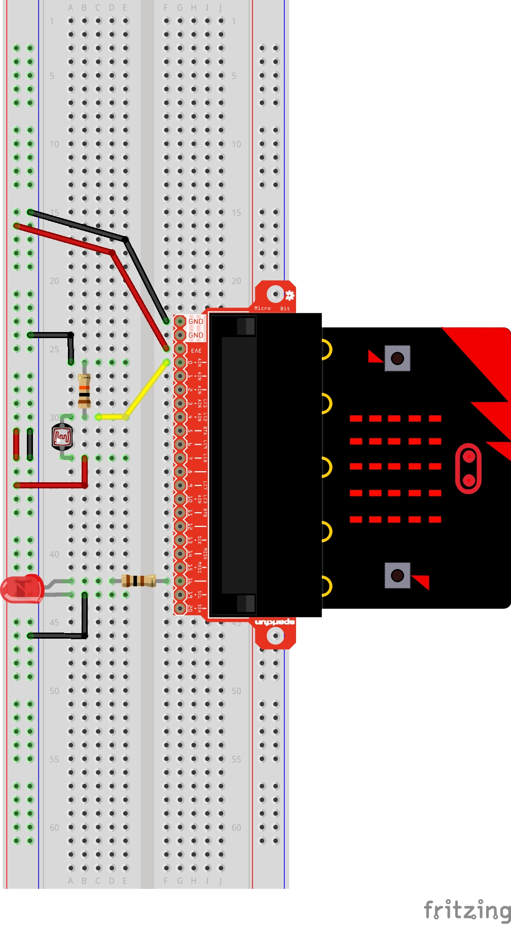
Ready to start hooking everything up? Check out the wiring diagram below to see how everything is connected.
| Polarized Components | Pay special attention to the component’s markings indicating how to place it on the breadboard. Polarized components can only be connected to a circuit in one direction. |
Let's read a photoresistor and turn on an LED when it reaches a certain value. Type (or copy) the program into your Mu editor, or download all the programs from this GitHub Repository and open the Ex3_readLDR.py program. Save it, then click the Flash icon to program your micro:bit.
language:python
# SparkFun Electronics
# Experiment 3.0
# Reading a Photoresistor

from microbit import *

calibrationVal = pin0.read_analog()
sleep(1000)

while True:
    lightVal = pin0.read_analog()
    if lightVal < calibrationVal-50:
        pin16.write_digital(1)
    else:
        pin16.write_digital(0)
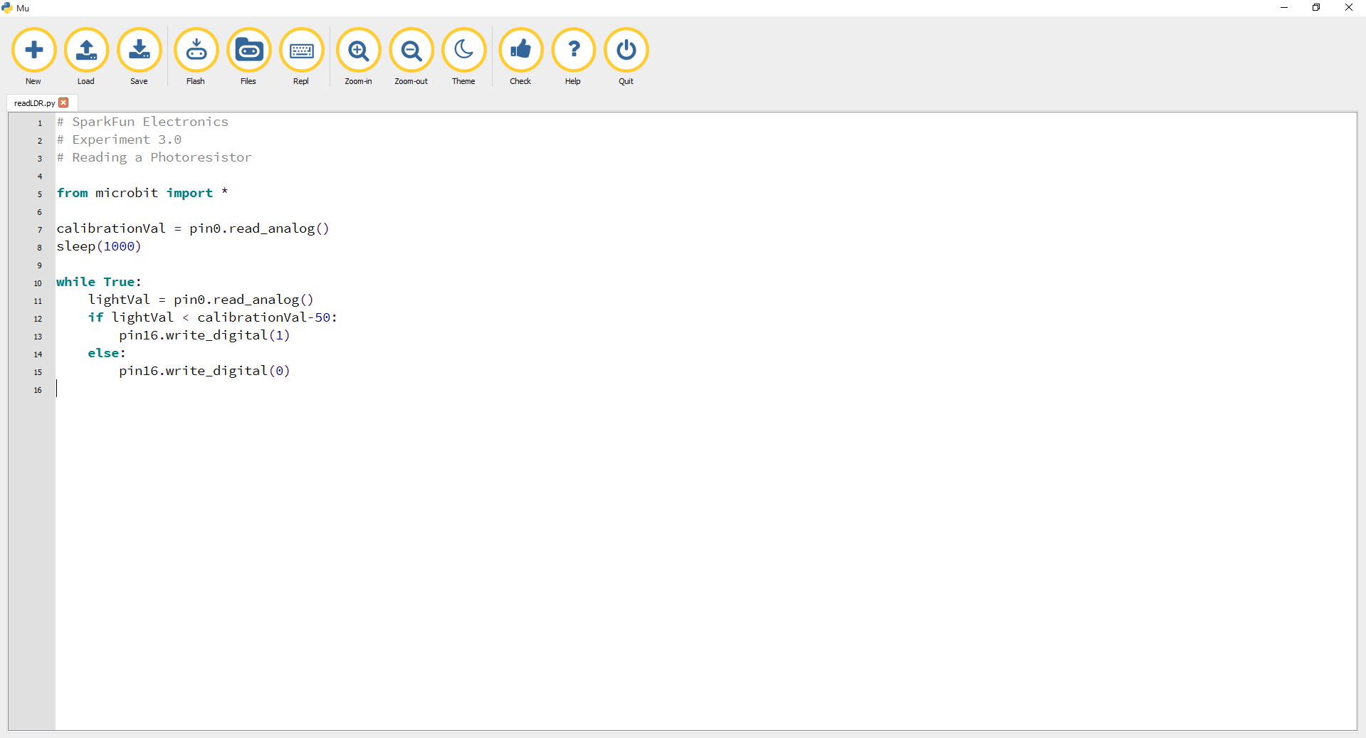
If the light value variable that is constantly being updated in the forever loop is less than the calibration value minus 50, it is dark and the LED should turn on. The (-50) portion of the if statement is a sensitivity value. The higher the value, the less sensitive the circuit will be; the lower the value, the more sensitive it will be to lighting conditions.
The if and else statements are a simple way to set the control flow of your forever loop. If the logical statement tied to the if statement is True, then it will execute the code indented under the colon. If that statement is False, it will skip to the next statement, which is else. In this case, if the statement is True (the room is dark), then the micro:bit will turn on the LED on pin 16; else (if the room is bright), it will turn the LED off using a write_digital() command covered earlier.
calibrationval is a calibration variable. Your micro:bit takes a single reading of the light sensor before entering the forever loop and uses this value to compare against the lightVal variable in the forever loop. This value doesn't change in the forever loop, as it is set before entering the forver loop. To update this value, you can press the RESET button on the back of your micro:bit or power cycle the board.
When the micro:bit runs the program, it will take a single reading from the light sensor and use that as a calibration value of the "normal" state of the room. When you place your hand over the light sensor or turn the lights off, the LED will turn on. If you turn the lights back on or uncover the light sensor, the LED will turn off.

You may have been leaning over the light sensor when the code started. Make sure the light sensor is reading the normal light in the room at startup. Try resetting the micro:bit.
Double-check your wiring of the signal pin; sometimes you miss a breadboard connection by a row.
You know what’s even more fun than a blinking LED? Changing colors with one LED! In this circuit you’ll learn how to use an RGB LED to create unique color combinations. Depending on how bright each diode is, nearly any color is possible!
You will need the following parts:
If you are conducting this experiment and didn't get the Inventor's Kit, we suggest using these parts:
Before continuing with this experiment, we recommend you be familiar with the concepts in the following tutorial:

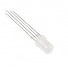
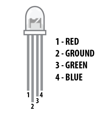
The Red/Green/Blue (RGB) LED is three LEDs in one. The RGB has four pins with each of the three shorter pins controlling an individual color: red, green or blue. The longer pin of the RGB is the common ground pin. You can create a custom-colored LED by turning different colors on and off to combine them. For example, if you turn on the red pin and green pin, the RGB will light up as yellow.
But which pin is which color? Pick up the RGB so that the longest pin (common ground) is aligned to the left as shown in the graphic below. The pins are Red, Ground, Green and Blue --- starting from the far left.
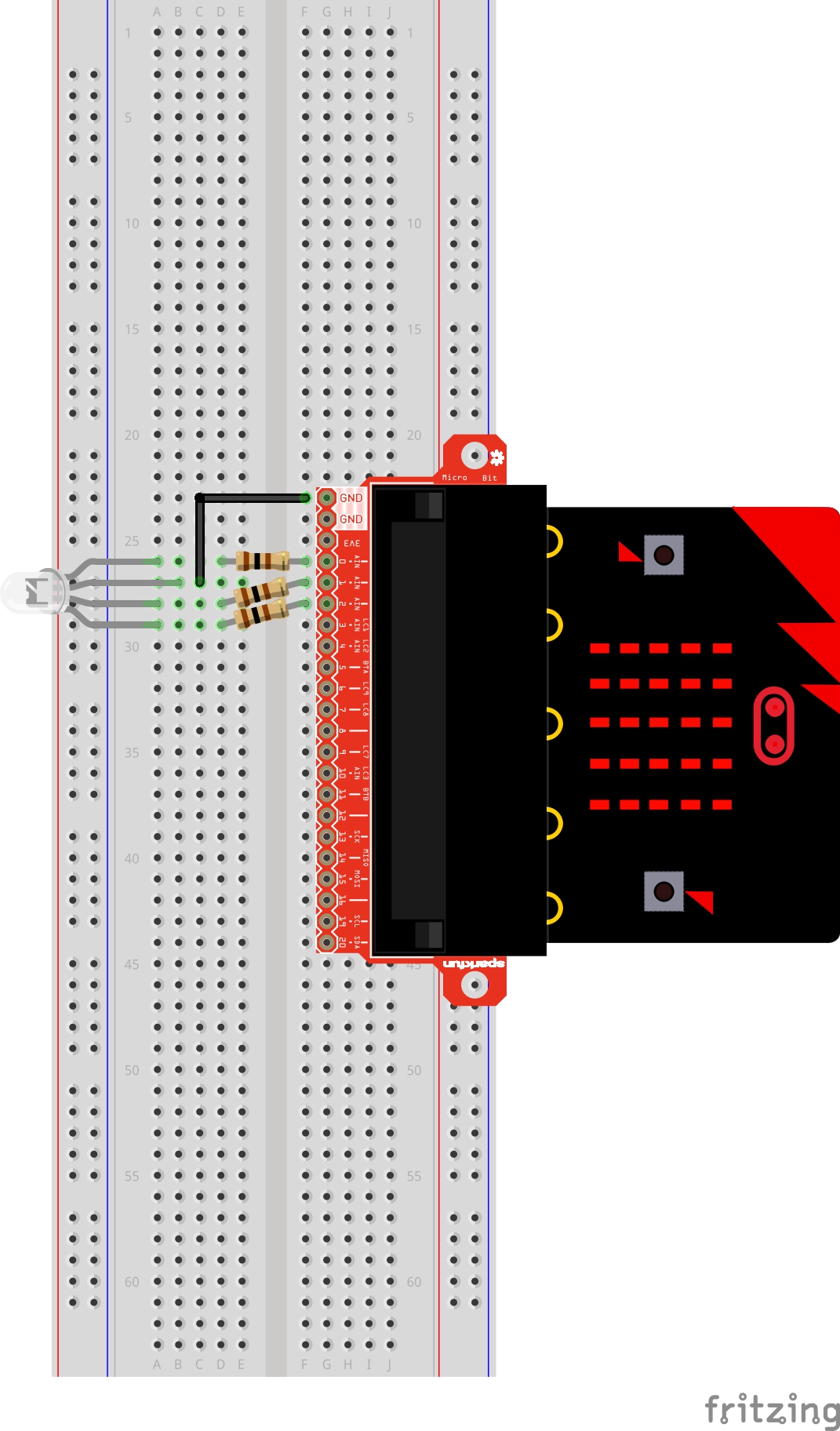
Ready to start hooking everything up? Check out the wiring diagram and hookup table below to see how everything is connected.
| Polarized Components | Pay special attention to the component’s markings indicating how to place it on the breadboard. Polarized components can only be connected to a circuit in one direction. |
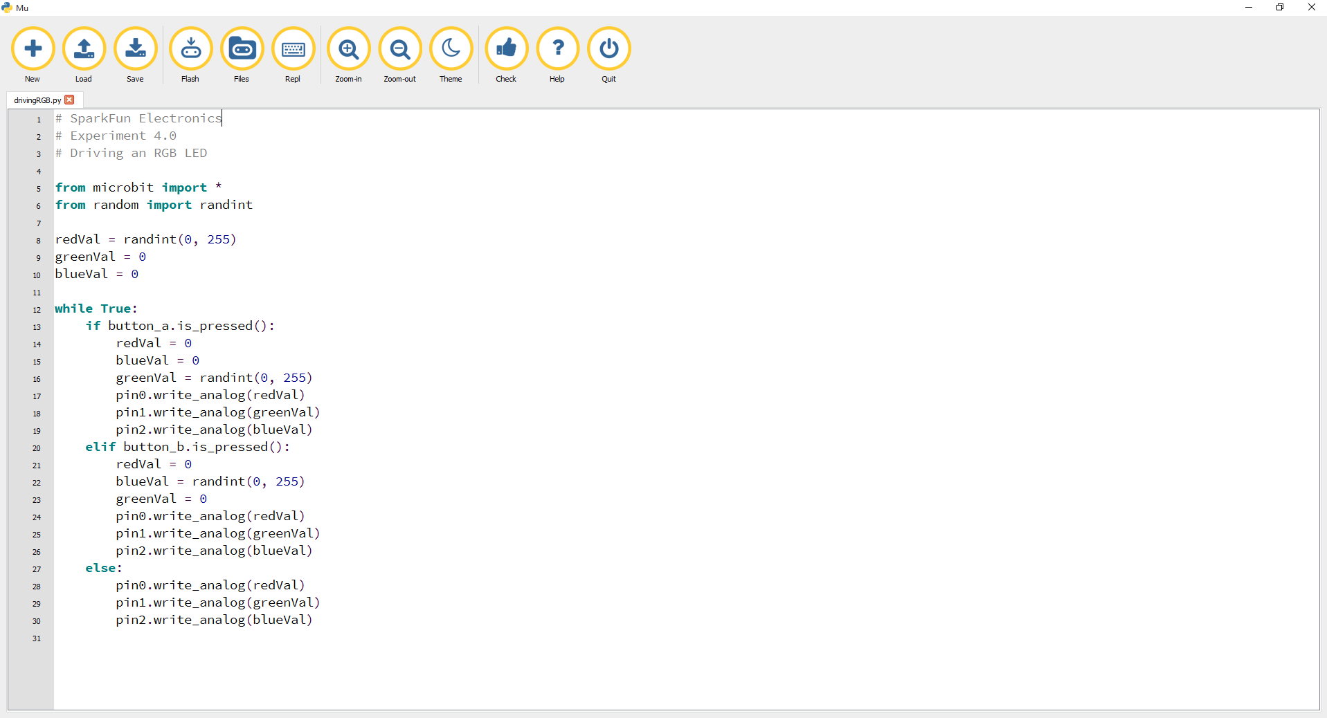
Let's drive an RGB LED. Type (or copy) the program into your Mu editor, or download all the programs from this GitHub Repository and open the Ex4_drivingRGB.py program. Save it, then click the Flash icon to program your micro:bit.
language:python
# SparkFun Electronics
# Experiment 4.0
# Driving an RGB LED

from microbit import *
from random import randint

redVal = randint(0, 255)
greenVal = 0
blueVal = 0

while True:
    if button_a.is_pressed():
        redVal = 0
        blueVal = 0
        greenVal = randint(0, 255)
        pin0.write_analog(redVal)
        pin1.write_analog(greenVal)
        pin2.write_analog(blueVal)
    elif button_b.is_pressed():
        redVal = 0
        blueVal = randint(0, 255)
        greenVal = 0
        pin0.write_analog(redVal)
        pin1.write_analog(greenVal)
        pin2.write_analog(blueVal)
    else:
        pin0.write_analog(redVal)
        pin1.write_analog(greenVal)
        pin2.write_analog(blueVal)
MicroPython comes with a random module to introduce a little unknown into your programs. There are a few ways you can use the random module beyond using it as a random number generator the way it is used in this experiment. To see the documentation, read the official docs on the random module.
In this experiment we are using random to generate a random number between 0 and 255
button_a and button_b represent the left and right buttons on the micro:bit respectively. There are three built-in functions that can be attached to button_a or button_b:
is_pressed() --- Will return True if the button specified is pressed. If the specified button is not pressed, it will return False.was_pressed() --- Will return True or False depending on whether the specified button was pressed since start-up or since the last time this statement (method) was called.get_pressed() --- Will return the number of times the specified button has been pressed since the device started or since the last time the statement (method) was used. Once the method is used, it will reset to zero.elifThe elif statement lets you check for multiple expressions that might be True. In this experiment we want to do different things whether button A pressed is True or button B pressed is True.
You should see your LED turn on red. If you press the A button on the micro:bit, the color will change to green, and if you press the B button, the color will change to blue. Try modifying the code to mix all three colors and display a white.

With the four pins of the LED so close together, it’s sometimes easy to misplace one. Double check that each pin is where it should be.
The red diode within the RGB LED may be a bit brighter than the other two. To make your colors more balanced, use a higher ohm resistor.
In this experiment you will use your first digital input: a switch. The SPDT (Single-Pole, Double-Throw) switch is a simple way to select between two options, especially when paired with an "if" state. You will use that switch to select which of the two LEDs will blink.
You will need the following parts:
If you are conducting this experiment and didn't get the Inventor's Kit, we suggest using these parts:
Before continuing with this tutorial, we recommend you be somewhat familiar with the concepts in these tutorials:

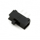
The Single-Pole, Double-Throw (SPDT) switch has a common pin in the middle and then two other pins that, depending on the location of the switch, are either connected to the common (center) pin or not. Reading a switch is similar to a button. You need to connect the common pin to a digital General Purpose Input/Output (GPIO) pin on your micro:bit and the other pins to 3.3V and ground. It doesn’t matter which pin is which. When you move the switch, the common pin will either be HIGH (connected to 3.3V) or LOW (connected to ground).
Ready to start hooking everything up? Check out the wiring diagram and hookup table below to see how everything is connected.
| Polarized Components | Pay special attention to the component’s markings indicating how to place it on the breadboard. Polarized components can only be connected to a circuit in one direction. |
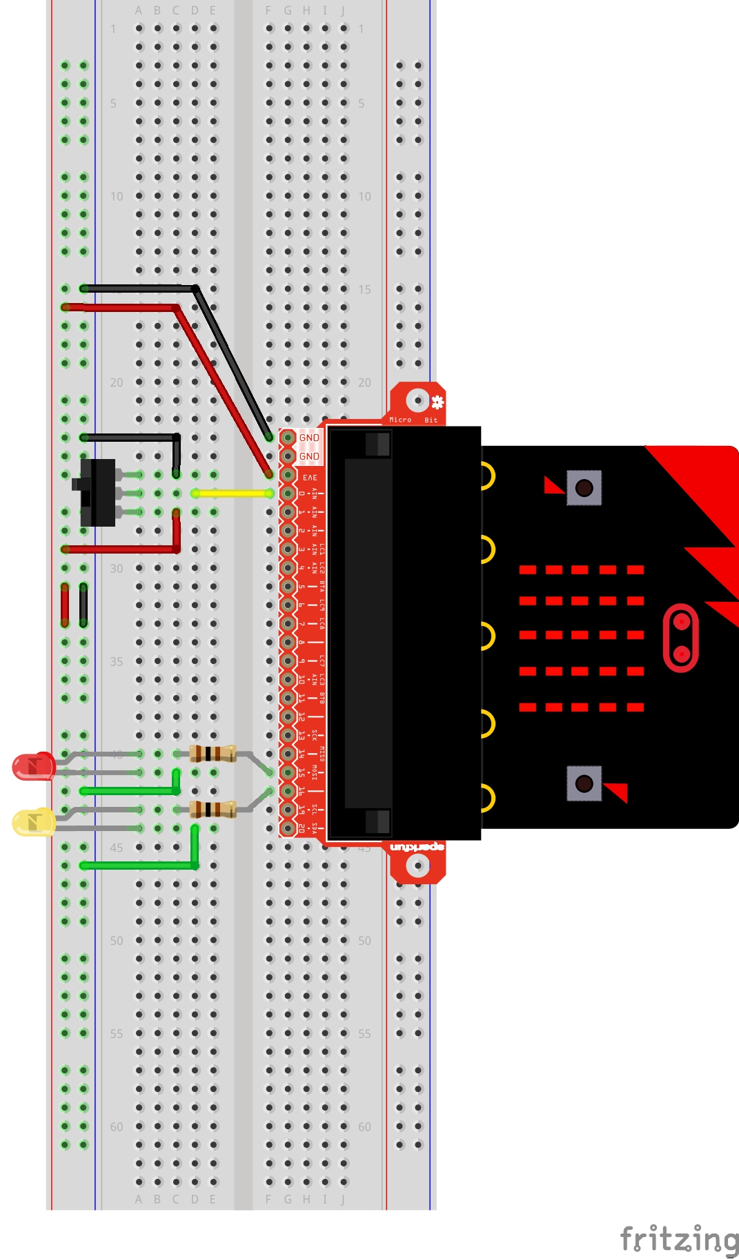
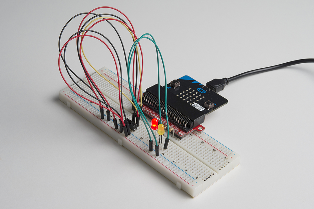
Let's read a SPDT switch and control some LEDs. Type (or copy) the program into your Mu editor, or download all the programs from this GitHub Repository and open the Ex5_readSPDT.py program. Save it, then click the Flash icon to program your micro:bit.
language:python
# SparkFun Electronics
# Experiment 5.0
# Reading an SPDT Switch

from microbit import *

while True:
    if pin0.read_digital():
        pin15.write_digital(1)
        sleep(1000)
        pin15.write_digital(0)
        sleep(1000)
    else:
        pin16.write_digital(1)
        sleep(500)
        pin16.write_digital(0)
        sleep(500)
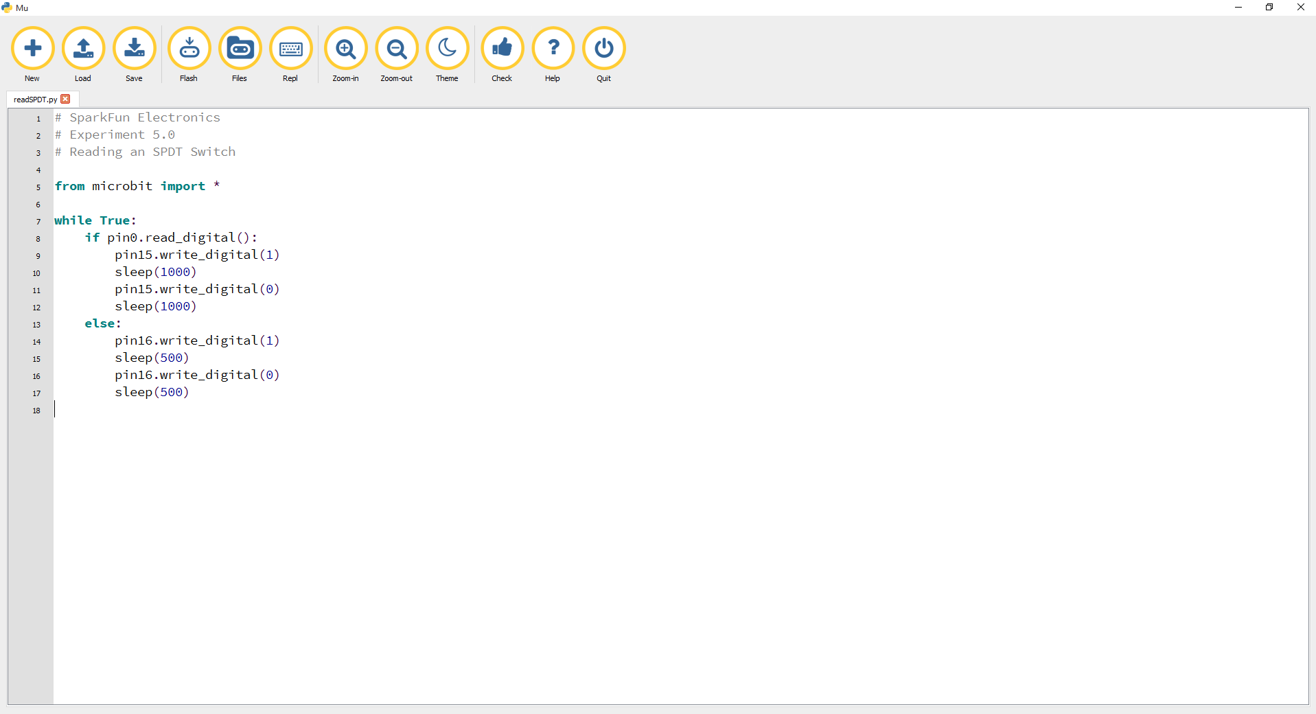
Just as the write_digital() statement turns a pin on (1) or off (0), the read_digital() statement determines the state of a pin, which is either HIGH (1) or LOW (0). By building a circuit that connects 3.3V or ground to a pin, we can detect if a switch is thrown or a button is pressed.
Depending on the state of the switch, a different LED will blink. If you move the switch to connect the signal pin to 3.3V (HIGH) then the LED connected to pin P15 will blink. If you flip the switch and ground the signal pin, then the LED on pin P16 will start blinking, and LED 1 will turn off.
The wires for the switch are right next to each other. Make sure that signal is in the center with voltage and ground on the outside pins. If you connect ground and voltage, your board will short out and shut down.
Make sure your power LED is on. If it is off, pull the signal wire and see if that changes anything. If you short circuit your micro:bit board, it will turn itself off to protect the circuitry.
No worries; these circuits are all super stripped-down to make playing with the components easy, but once you throw them together, the sky is the limit.
Up until now, we’ve focused mostly on outputs. Now we’re going to go to the other end of the spectrum and play around with inputs. In Experiment 2, we used an analog input to read the potentiometer. In this experiment, we’ll be reading one of the most common and simple inputs --- a push button --- by using a digital input. We will use it to cycle through different colors on the RGB.
You will need the following parts:
If you are conducting this experiment and didn't get the Inventor's Kit, we suggest using these parts:
Before continuing with this experiment, we recommend you be somewhat familiar with the concepts in these tutorials:
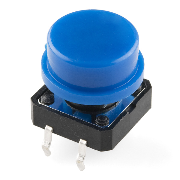
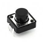
A momentary push button closes or completes the circuit only while it is being pressed. The button has four pins, which are broken out into two sets of two pins. When you press down on the button and get a nice "click," the button bridges the two sets of pins and allows current to flow through the circuit.
How do you know which pins are paired up? The buttons included in this kit will only fit across the breadboard ditch in one direction. Once you get the button pressed firmly into the breadboard (across the ditch), the pins are horizontally paired. The pins toward the top of the breadboard are connected, and the pins toward the button of the breadboard are connected.
Ready to start hooking everything up? Check out the wiring diagram and hookup table below to see how everything is connected.
| Polarized Components | Pay special attention to the component’s markings indicating how to place it on the breadboard. Polarized components can only be connected to a circuit in one direction. |
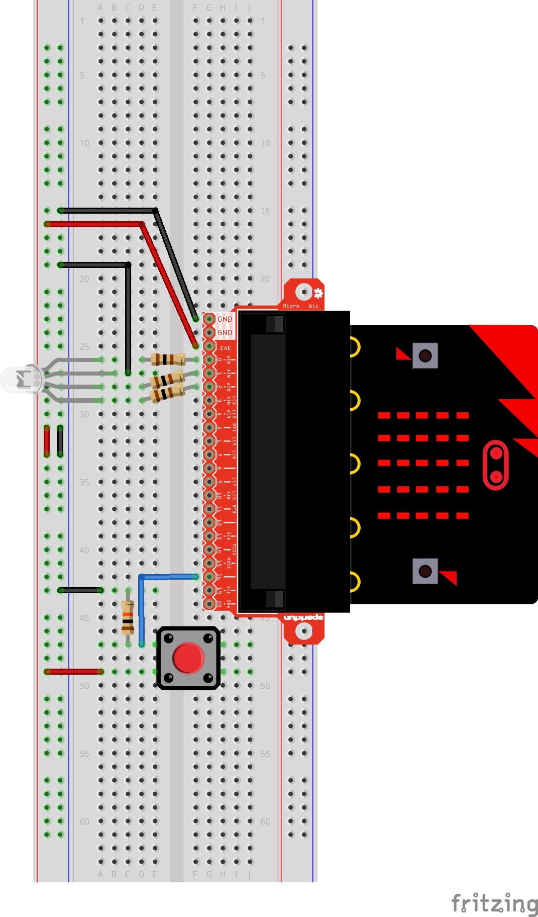
Let's read a button press and control an RGB LED. Type (or copy) the program into your Mu editor, or download all the programs from this GitHub Repository and open the Ex6_readButton.py program. Save it, then click the Flash icon to program your micro:bit.
language:python
# SparkFun Electronics
# Experiment 6.0
# Reading a button press

from microbit import *

led_pins = [pin0, pin1, pin2]
led_states = [(255, 0, 0), (0, 255, 0), (0, 0, 255)]
led_states_iter = iter(led_states)
RED = 0
GREEN = 1
BLUE = 2

while True:
    while pin16.read_digital() == 0:
        pass
    while pin16.read_digital() == 1:
        pass
    try:
        led_state = next(led_states_iter)
    except:
        led_states_iter = iter(led_states)

    pin0.write_analog(led_state[RED])
    pin1.write_analog(led_state[GREEN])
    pin2.write_analog(led_state[BLUE])
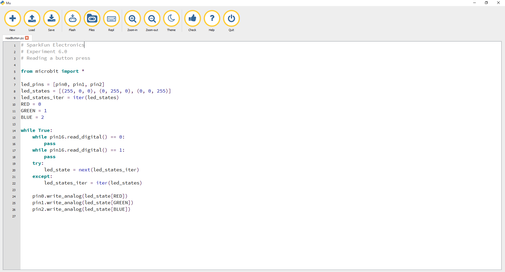
Pins on the micro:bit are active-low, which means external buttons should be connected to the pin and to ground to trigger an event with a button. This cannot be changed in MicroPython the way it can be changed in MakeCode. We have also found that MicroPython has a very hard time with interrupts and can't seem to run more than one thread at a time. With MakeCode, it is possible to run multiple threads.
Since interrupts are very difficult in MicroPython, we decided to use pass. pass is a way to handle external triggers from a while loop without impacting the while loop. In this case, the external trigger is whether or not the button has been pressed. It is a kind of cheat to using interrupts. We can continuously poll pin 16 on the micro:bit to see if the button has been pressed or not.
The iter()_method creates an object that can be iterated or incremented one element at a time until a specified end. At the end of the iteration, an exception is raised: "StopIteration."
try and except allows a program to catch an unexpected (or expected in this case) error and handle the error however the programmer wants to. The error in this case would be how the iter function lets the program know it is past the last iterable value. The exception that is thrown by the iter method is "StopIteration." We are "trying" next iter until the exception is thrown. Once the exception is thrown, we exit from try and move onto except, which will start the iterator over again.
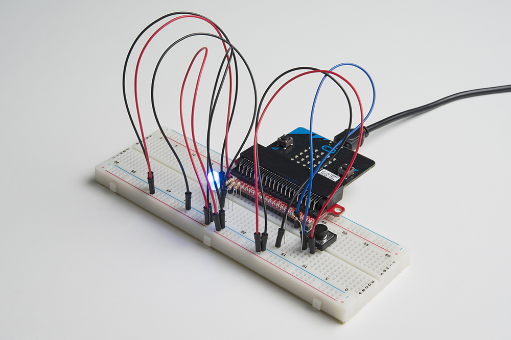
When you press the button, the RGB will turn on to a color. When you press it again, the color will change, and another press will change the color once again. Press it one more time, and it will turn off. Every time you press the button, it increments a variable, and then we check against it to set the color. If the variable goes over the value of 2, we reset it to 0, which is off.
The push button is square, and because of this it is easy to put it in the wrong way. Give it a 90-degree twist and see if it starts working.
No worries; these circuits are all super stripped-down to make playing with the components easy, but once you throw them together, the sky is the limit. Remember, though, that these are building blocks to the Iron Man suit.
A temperature sensor is exactly what it sounds like --- a sensor used to measure ambient temperature. In this experiment you will read the raw 0--1023 value from the temperature sensor, calculate the actual temperature and then print it out over the LED array on your micro:bit.
You will need the following parts:
If you are conducting this experiment and didn't get the Inventor's Kit, we suggest using these parts:
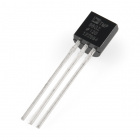
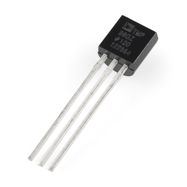
The TMP36 is a low-voltage precision centigrade temperature sensor. It provides a voltage output that is linearly proportional to the Celsius temperature. It also doesn’t require any external calibration to provide typical accuracies of ±1°C at +25°C and ±2°C over the −40°C to +125°C temperature range. The output voltage can easily convert to temperature using the scale factor of 10 mV/°C.
If you are looking at the flat face with text on it, the center pin is your signal pin, the left-hand pin is supply voltage (3.3V in this tutorial), and the right-hand pin connects to ground.
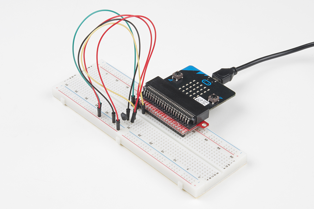
Ready to start hooking everything up? Check out the wiring diagram below to see how everything is connected.
| Polarized Components | Pay special attention to the component’s markings indicating how to place it on the breadboard. Polarized components can only be connected to a circuit in one direction. |
Please note: The temperature sensor can only be connected to a circuit in one direction. See below for the pin outs of the temperature sensor --- TMP36.
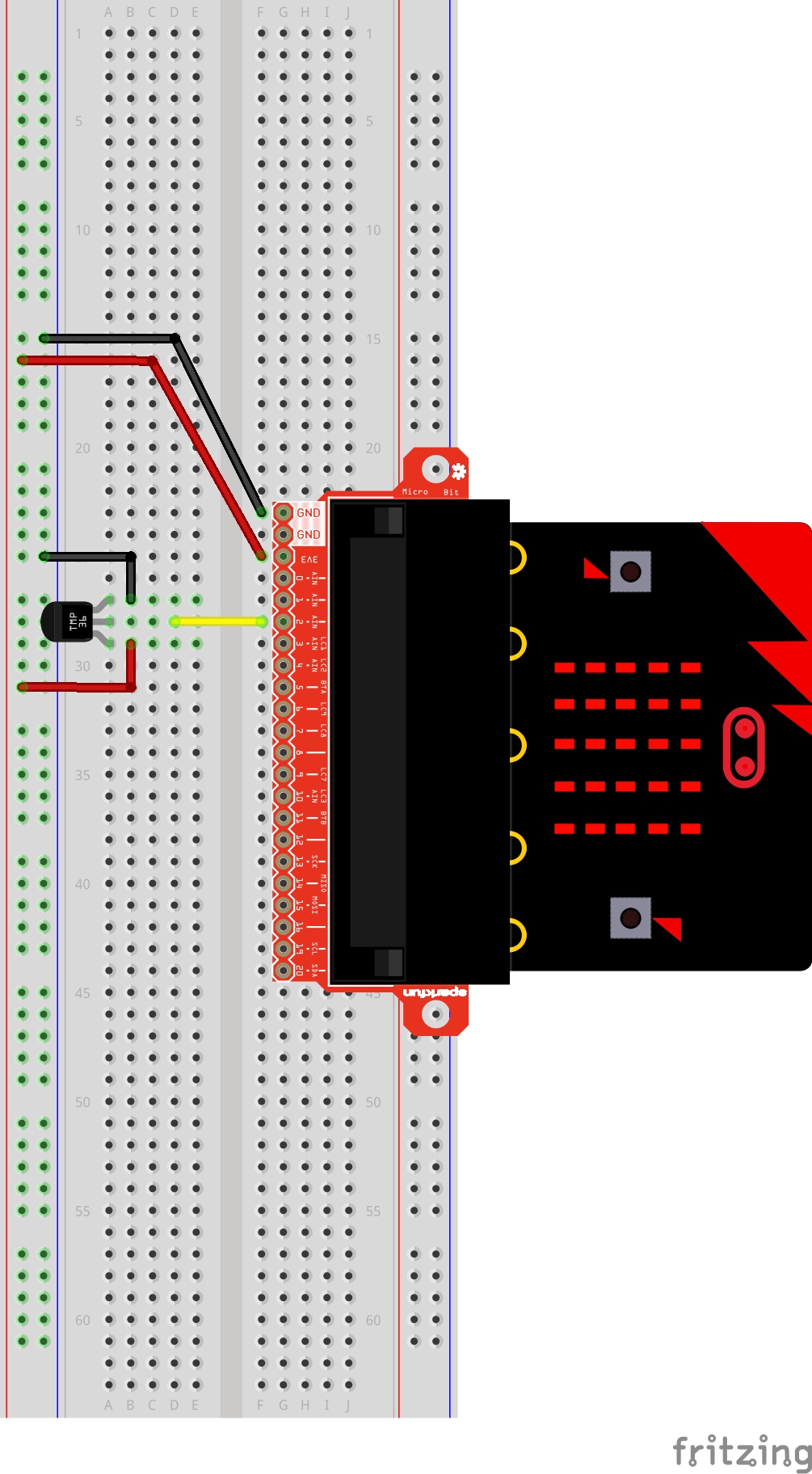
Let's read a temperature sensor. Type (or copy) the program into your Mu editor, or download all the programs from this GitHub Repository and open the Ex7_readTemp.py program. Save it, then click the Flash icon to program your micro:bit.
language:python
# SparkFun Electronics
# Experiment 7.0
# Reading a Temp Sensor

from microbit import *

while True:
    rawTemp = pin2.read_analog()
    degC = (((rawTemp*3.3)/(1023))-0.5)*100
    display.scroll(str(degC))
    sleep(1000)
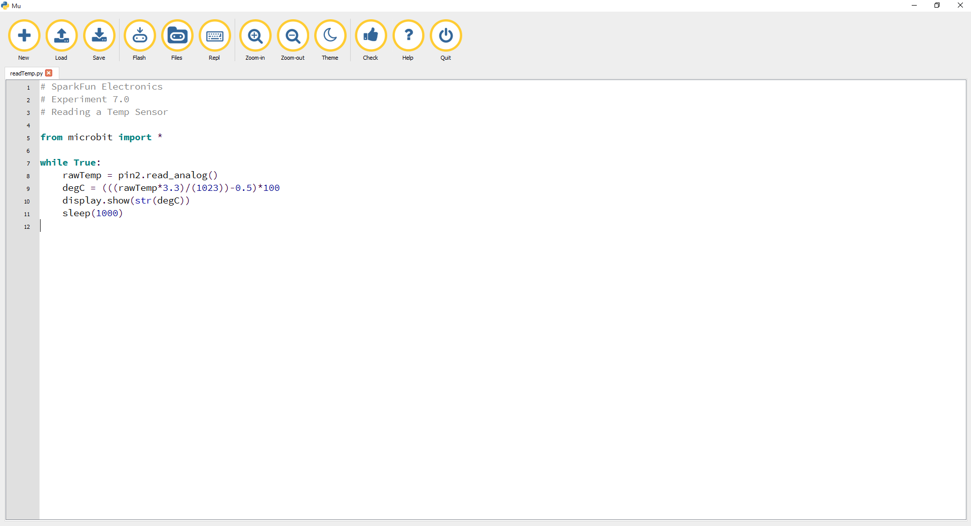
We have already covered display.scroll() but we need to convert our number (temperature) to a string (type) before displaying it to the micro:bit 5x5 LED array. Type conversion in MicroPython is a snap with a simple str placed in front of the variable holding the temperature of type number.
When your micro:bit turns on, the temperature reading from the TMP36 temperature sensor will be displayed and scrolled across the LED array.
Try pinching the sensor with your fingers to heat it up or pressing a bag of ice against it to cool it down.
If you see an output with "65525", "65533", "65527", etc. on the LEDs, the issue might be due to a loose (or possibly shorted) connection between the 3.3V pin and the TMP36's voltage input pin. The analog pin will probably start reading random values or there is a slight current draw to the temperature sensor from the micro:bit. Make sure that you check your connections by ensuring that there are no loose connections or pins touching where they should not. If you are using alligator clips, make sure that the connection is secure as well and that there are no shorts (try sliding the sheath around the alligator clips for more insulation).
You have wired it backward! Unplug your micro:bit immediately, let the sensor cool down and double check your wiring. If you catch it soon enough, your sensor may not have been damaged and may still work.
This experiment is your introduction to the servo motor, which is a smart motor that you can tell to rotate to a specific angular location. You will program it to rotate to a series of locations, then sweep across its full range of motion, and then repeat.
You will need the following parts:
If you are conducting this experiment and didn't get the Inventor's Kit, we suggest using these parts:
Before continuing with this experiment, we recommend you be familiar with the concepts in the following tutorial:

Unlike the action of most motors that continuously rotate, a servo motor can rotate to and hold a specific angle until it is told to rotate to a different angle. You can control the angle of the servo by sending it a PWM (Pulse Width Modulation) pulse train; the PWM signal is mapped to a specific angle from 0 to 180 degrees.
Inside of the servo there is a gearbox connected to a motor that drives the shaft. There is also a potentiometer that gives feedback on the rotational position of the servo, which is then compared to the incoming PWM signal. The servo adjusts accordingly to match the two signals.
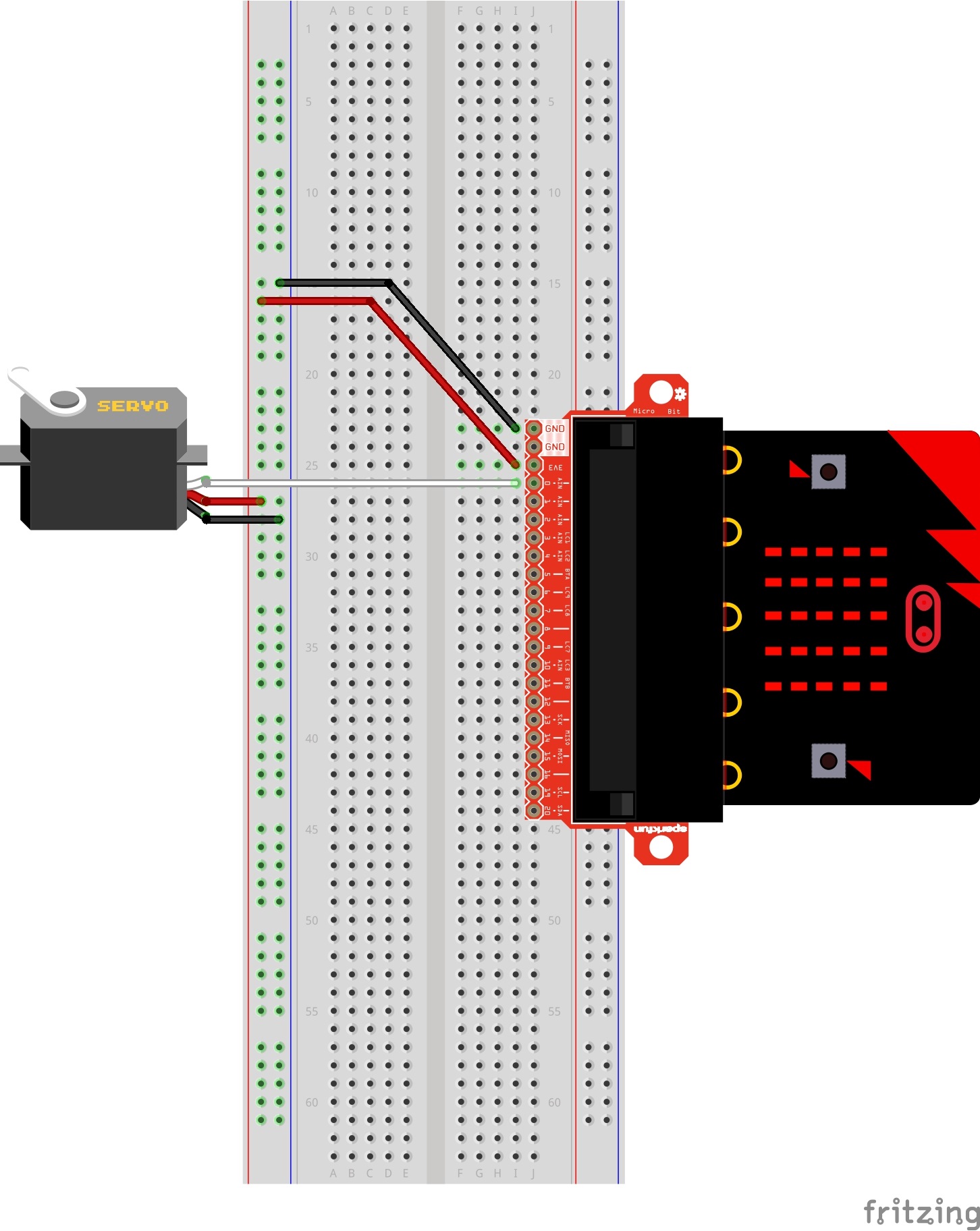
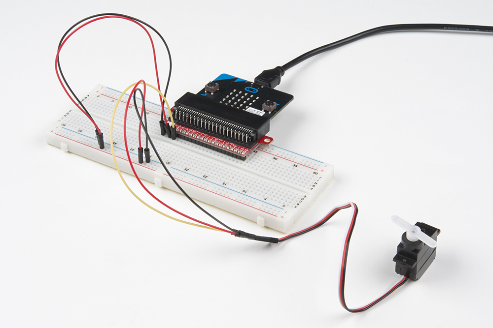
In this experiment, the servo is powered through 3.3 volts on the red wire and ground on the black wire; the white wire is connected to pin P0.
Ready to start hooking everything up? Check out the wiring diagram below to see how everything is connected.
| Polarized Components | Pay special attention to the component’s markings indicating how to place it on the breadboard. Polarized components can only be connected to a circuit in one direction. |
Connect 3x jumper wires to the female 3-pin header on the servo. This will make it easier to breadboard the servo.
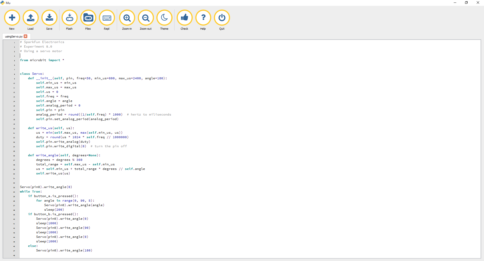
Let's drive a servo. Type (or copy) the program into your Mu editor, or download all the programs from this GitHub Repository and open the Ex8_usingServo.py program. Save it, then click the Flash icon to program your micro:bit.
language:python
# SparkFun Electronics
# Experiment 8.0
# Using a servo motor

from microbit import *


class Servo:
    def __init__(self, pin, freq=50, min_us=600, max_us=2400, angle=180):
        self.min_us = min_us
        self.max_us = max_us
        self.us = 0
        self.freq = freq
        self.angle = angle
        self.analog_period = 0
        self.pin = pin
        analog_period = round((1/self.freq) * 1000)  # hertz to miliseconds
        self.pin.set_analog_period(analog_period)

    def write_us(self, us):
        us = min(self.max_us, max(self.min_us, us))
        duty = round(us * 1024 * self.freq // 1000000)
        self.pin.write_analog(duty)
        sleep(100)
        self.pin.write_digital(0)  # turn the pin off

    def write_angle(self, degrees=None):
        if degrees is None:
            degrees = math.degrees(radians)
        degrees = degrees % 360
        total_range = self.max_us - self.min_us
        us = self.min_us + total_range * degrees // self.angle
        self.write_us(us)


Servo(pin0).write_angle(0)
while True:
    if button_a.is_pressed():
        for angle in range(0, 90, 5):
            Servo(pin0).write_angle(angle)
            sleep(200)
    if button_b.is_pressed():
        Servo(pin0).write_angle(0)
        sleep(1000)
        Servo(pin0).write_angle(90)
        sleep(1000)
        Servo(pin0).write_angle(0)
        sleep(1000)
    else:
        Servo(pin0).write_angle(180)
One of the major drawbacks to using MicroPython with the micro:bit is that you can't import third-party modules in Mu. Or at least, we haven't had any luck flashing two Python files in the editor to the micro:bit. This code seems long because we had to paste the Servo Class code into our script for ease of use [1]. Ignoring the Servo Class code, let's look at what's happening inside the forever loop.
while True: is executed as explained earlier. The other option is to save the module as servo.py, place it in the root directory of your computer, and then import it using the following code:# from servo.py import the Servo class
from servo import ServoThe range function generates a list of numbers. In this experiment we are generating a list from 0--90 that increases by 5.
The Servo Class is called in statement with pin 0 as its argument. The .write_angle() function is how the servo is moved --- by the number specified in the parentheses mapped to degrees on the servo motor.
When powered up you should see the servo move to a single location (0 degrees) and then start to sweep to 180 degrees back and forth until you turn it off or tell it to go to a different angle.
Even with colored wires, it is still shockingly easy to plug a servo in backward. This might be the case.
A mistake we made a time or two was simply forgetting to connect the power (red and black wires) to 3.3 volts and ground (GND).
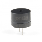
In this experiment, we will again bridge the gap between the digital world and the analog world. We'll be using a piezo buzzer that makes a small "click" when you apply voltage to it (try it!). By itself that isn't terribly exciting, but if you turn the voltage on and off hundreds of times a second, the piezo buzzer will produce a tone. And if you string a bunch of tones together, you've got music! This circuit and set of code blocks will create a simple sound machine.
You will need the following parts:
If you are conducting this experiment and didn't get the Inventor's Kit, we suggest using these parts:

The buzzer is a small component with a piece of metal in it that moves when you apply a voltage across it. This motion causes a small sound, or "click." If you turn the voltage on and off fast enough, you get different beeps, squeals, chirps and buzzes. You will use PWM to control the speed of turning the piezo on and off --- and, in turn, the audio frequency coming out of the buzzer. Adjusting the PWM enables you to get legitimate notes out of the buzzer.
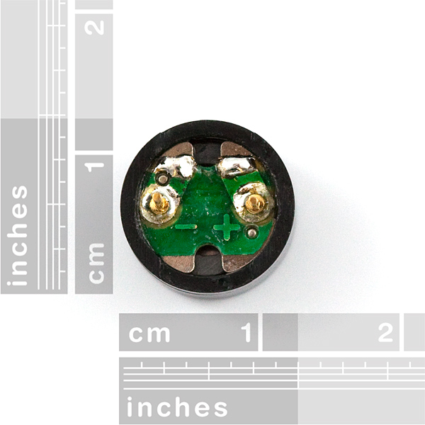
If you flip the buzzer over and look at the bottom, you will see that one pin has a (+) next to it. That pin gets connected to a signal from the P0 pin. The other pin should be connected to ground.
For users with a micro:bit v2, there is also a built-in piezo buzzer. We will be focusing on wiring an external piezo buzzer.
Ready to start hooking everything up? Check out the wiring diagram below to see how everything is connected.
| Polarized Components | Pay special attention to the component’s markings indicating how to place it on the breadboard. Polarized components can only be connected to a circuit in one direction. |

Let's drive a buzzer. Type (or copy) the program into your Mu editor, or download all the programs from this GitHub Repository and open the Ex9_usingBuzzer.py program. Save it, then click the Flash icon to program your micro:bit.
speaker.off() by using a single line comment (i.e. #) before compiling and downloading the program in the editor. language:python
# SparkFun Electronics
# Experiment 9.0
# Using a buzzer
from microbit import *
import music
# disable built-in speaker on micro:bit v2 and output to external speaker from pin P0
speaker.off()
while True:
if pin15.read_digital() == 1:
music.play("C4:8")
elif pin16.read_digital() == 1:
music.play("D1:8")
else:
pass
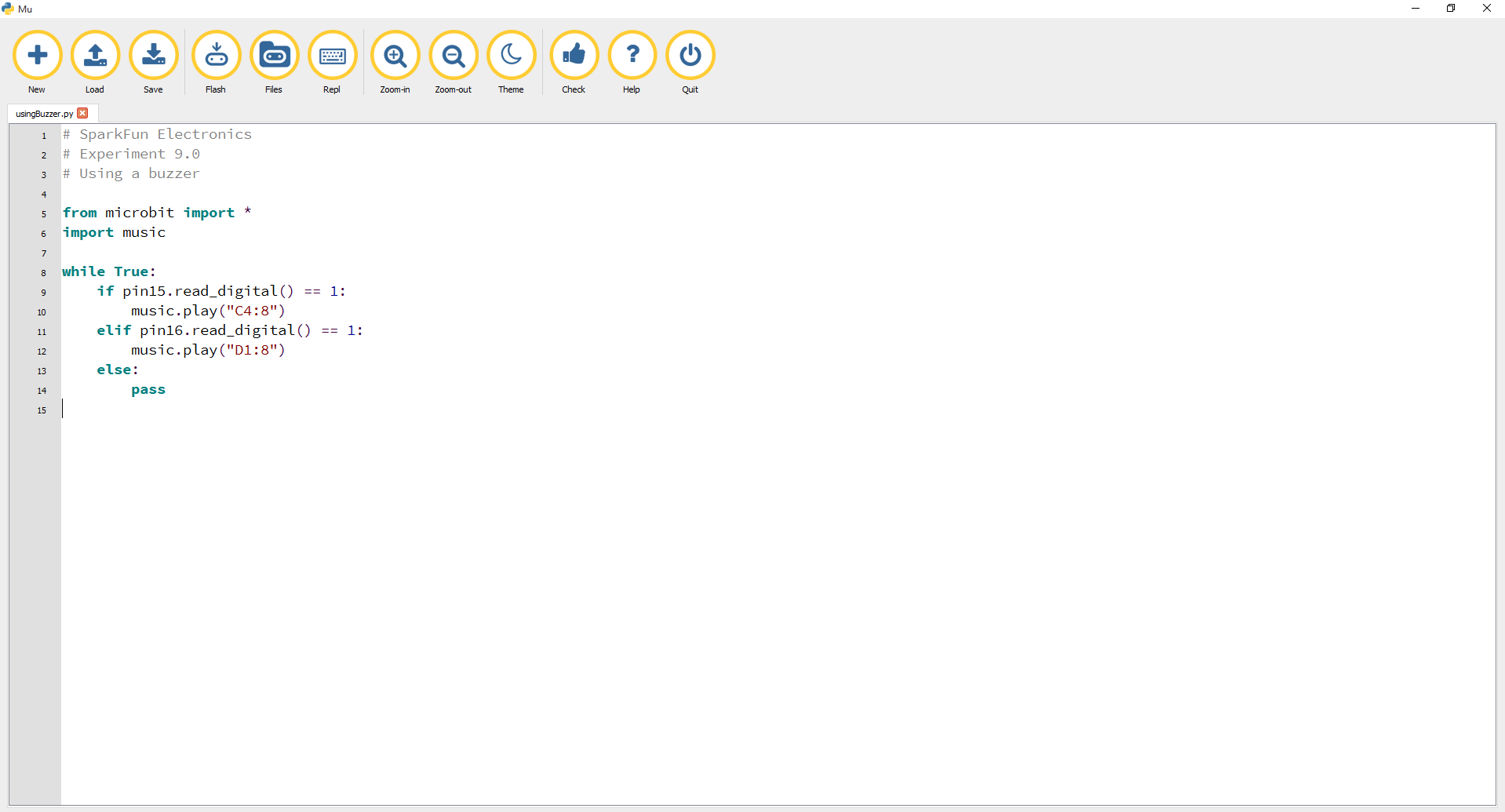
The `speaker.off() function disables the built-in speaker on the micro:bit v2 and outputs a signal to the external piezo buzzer from P0. For users that are using micro:bit v1 boards, simply comment out this function before compiling and downloading the program in the editor.
MicroPython has an awesome music and sound module. We spent hours generating tones and writing songs in the REPL. As you learn to compose your own music on the micro:bit we highly recommend using the REPL to become familiar with all the sounds --- plus the help() feature is nice when you want to see (hear) what you can do.
The music module has 21 melodies built in. To see a list, begin typing music.play(_... in the Mu editor, and the list should pop up.
To get an in-depth tutorial on the music module, click here.
To play a tune you need to specify a note (A, C#, F), an octave (0--8) and a duration (how long the note will be played). For example, if the button on pin 15 is pressed, the note C in octave 4 will play for a duration of 8.
What you should see --- well, nothing! What you should hear --- each button has its own tune. Enjoy your sound machine and feel free to swap out the song and tunes of your choice. Add more buttons and play statements to make your custom piano!

Try wiring a potentiometer between the buzzer and pin 0. Adding a potentiometer will adjust the volume. Adjust the code where it says speaker.off() to speaker.on() will also output sound to the built-in speaker.
Try it again but with a real speaker. At the press of a button you could play the funeral march, Happy Birthday or the Nyan Cat theme with much better audio!
Given the size and shape of the piezo buzzer, it is easy to miss the right holes on the breadboard. Try double checking its placement.
Also, double check to make sure the push button is wired correctly. If you miswired it, then the circuit will never be completed, whether you press the button or not.
In this experiment you will look at combining the use of the accelerometer on the micro:bit to measure the orientation of the micro:bit and using it to control the angle of a servo.
Ready to shake, rattle and roll?
You will need the following parts:
If you are conducting this experiment and didn't get the Inventor's Kit, we suggest using these parts:
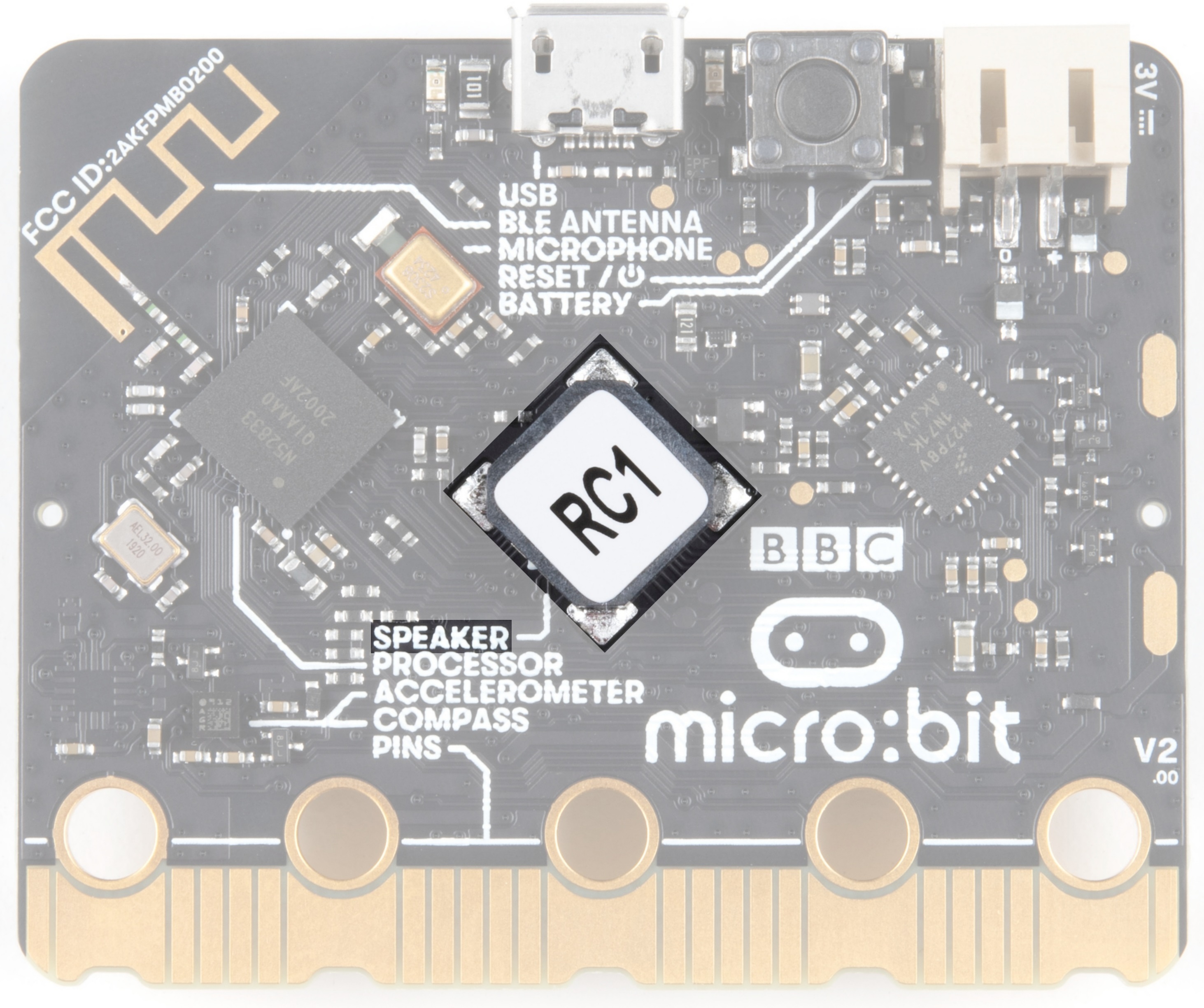
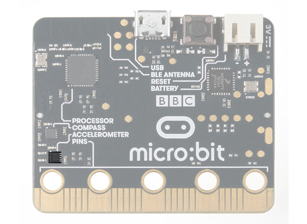
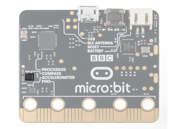
The accelerometer is a component that you won't find in the kit's bag of parts. Why? Because it is on the micro:bit itself! On the back of the micro:bit you can see a number of small chips. One of them is the accelerometer. The micro:bit has an onboard accelerometer that measures gravitational force. Depending on the version that you have, the accelerometer and compass can be on separate ICs or combined into a single IC.
 |
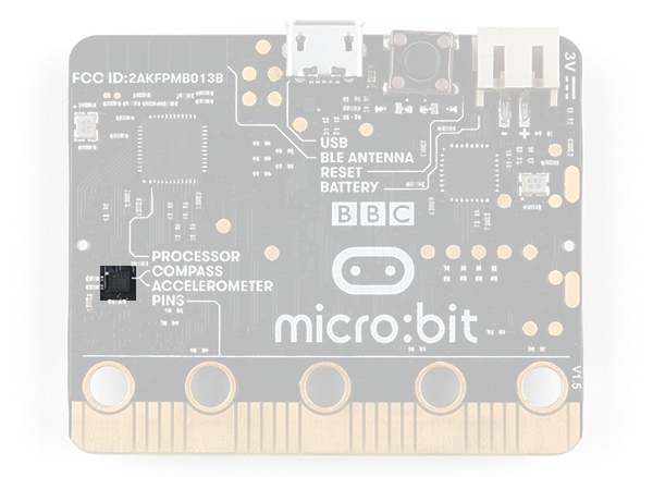 |
| v1.0 w/ Accelerometer on Separate IC | v1.5 w/ Combined Accelerometer and Magnetometer |
An accelerometer is a sensor that measures the gravitational forces pulling on it in all three dimensions of the chip's X, Y and Z axes.
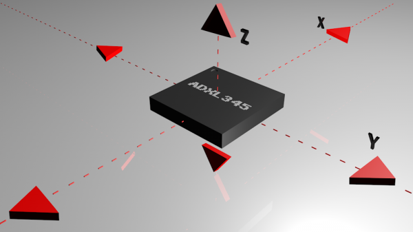
Not only can an accelerometer measure the raw forces pulling on the chip and the object that the chip is sitting on, but it can also detect steps, shakes and other motions that have a specific pattern. On top of that, you can use an accelerometer to simply detect the orientation of the device. Did you ever wonder how your phone knows when you turn it from portrait to landscape? It is all because of the accelerometer in your phone!
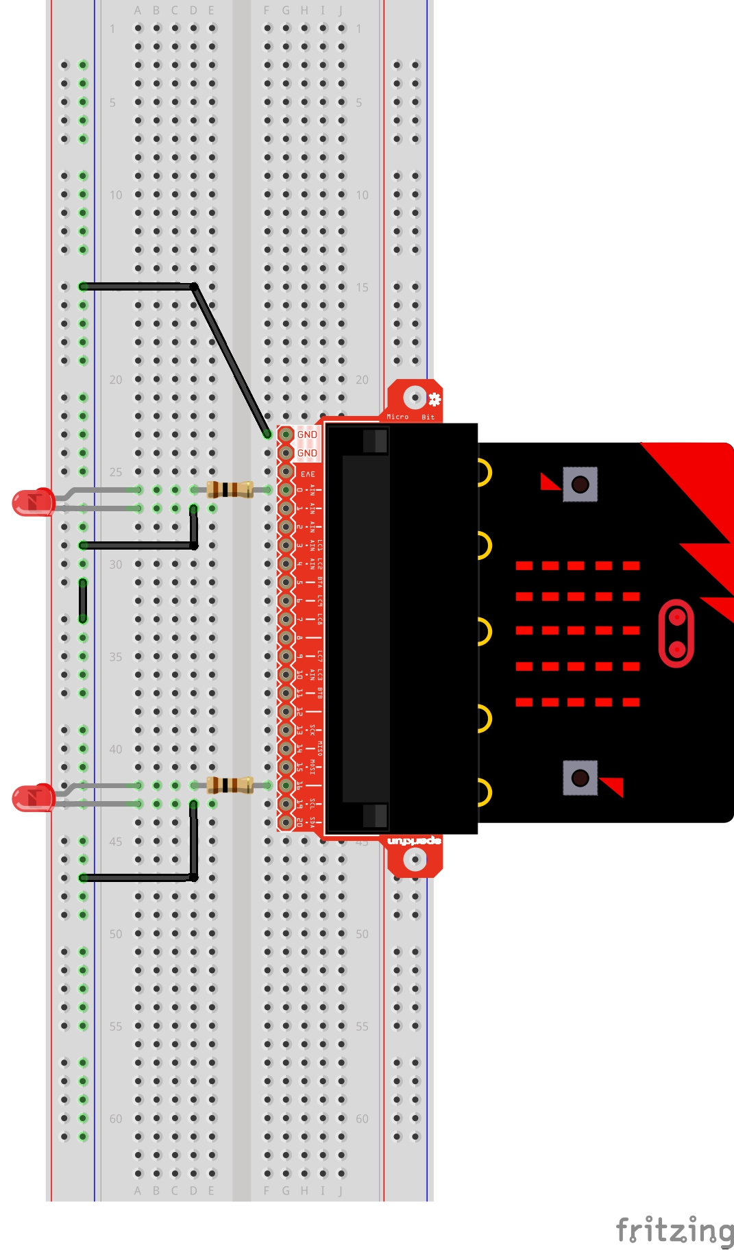
Ready to start hooking everything up? Check out the wiring diagram below to see how everything is connected.
| Polarized Components | Pay special attention to the component’s markings indicating how to place it on the breadboard. Polarized components can only be connected to a circuit in one direction. |
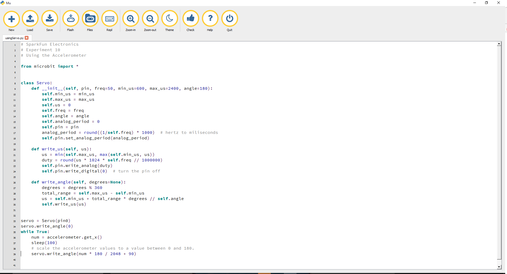
Let's read an accelerometer and control a servo. Type (or copy) the program into your Mu editor, or download all the programs from this GitHub Repository and open the Ex10_usingAccel.py program. Save it, then click the Flash icon to program your micro:bit.
language:python
# SparkFun Electronics
# Experiment 10
# Using the Accelerometer

from microbit import *


class Servo:
    def __init__(self, pin, freq=50, min_us=600, max_us=2400, angle=180):
        self.min_us = min_us
        self.max_us = max_us
        self.us = 0
        self.freq = freq
        self.angle = angle
        self.analog_period = 0
        self.pin = pin
        analog_period = round((1/self.freq) * 1000)  # hertz to miliseconds
        self.pin.set_analog_period(analog_period)

    def write_us(self, us):
        us = min(self.max_us, max(self.min_us, us))
        duty = round(us * 1024 * self.freq // 1000000)
        self.pin.write_analog(duty)
        sleep(100)
        self.pin.write_digital(0)  # turn the pin off

    def write_angle(self, degrees=None):
        if degrees is None:
            degrees = math.degrees(radians)
        degrees = degrees % 360
        total_range = self.max_us - self.min_us
        us = self.min_us + total_range * degrees // self.angle
        self.write_us(us)


Servo(pin0).write_angle(0)
while True:
    num = accelerometer.get_x()
    Servo(pin0).write_angle(num * 180 / 2048 + 90)
Ignoring the servo class code again [1], we've got some new stuff!
The accelerometer module comes with five built-in functions and recognizes 11 gestures. To see the full documentation, click here. The accelerometer.get_x() statement will return the acceleration measurement on the x-axis as a number between -1024 and 1024, depending on the direction.
Since the value stored in num needs to translated to an angle between 0-180 from a range between -1024 and 1024 it needs to be scaled. Adding 90 to the scaled value sets a range of angles for the negative accelerometer values from 0-89, and positive accelerometer values from 90-180.
At the beginning of the program the servo should move to 0 degrees and then react to the orientation of the micro:bit. If you hold the micro:bit flat, the servo will be at 90 degrees. Then if you tilt the servo to the left, it will move less than 90 degrees toward the value of 0. If you move it to the right, the servo will move toward 180.
You may be holding the micro:bit in a different orientation. Flip it around and try again!
Double check your wiring! Remember, red to 3.3 volts, black to ground, and white to signal.
This experiment is just plain fun! Have you ever used a compass? Are you a little confused in terms of which direction to go? Fear not! We will build a digital compass that will keep you on track to the North Pole using the micro:bit's onboard compass chip!
You will need the following parts:
If you are conducting this experiment and didn't get the Inventor's Kit, we suggest using these parts:
In the previous experiment you learned about the accelerometer, which measured gravity. The compass, or technically the magnetometer, measures a magnetic field. Magnetic fields come in different sizes, but the biggest is the one produced by Earth itself, which is why compasses work.
The micro:bit has an onboard compass (a.k.a. a magnetometer) that can detect its orientation using Earth's magnetic field. Depending on the version that you have, the accelerometer and compass can be on separate ICs or combined into a single IC.
 |
|
| v1.0 w/ Magnetometer On Separate IC | v1.5 w/ Combined Accelerometer and Magnetometer |
The magnetometer detects magnetic north and then represents your heading in degrees with north being 0 degrees, east being 90 degrees, south being 180 degrees and west being 270. Pretty cool! Now let's put this compass to good use!
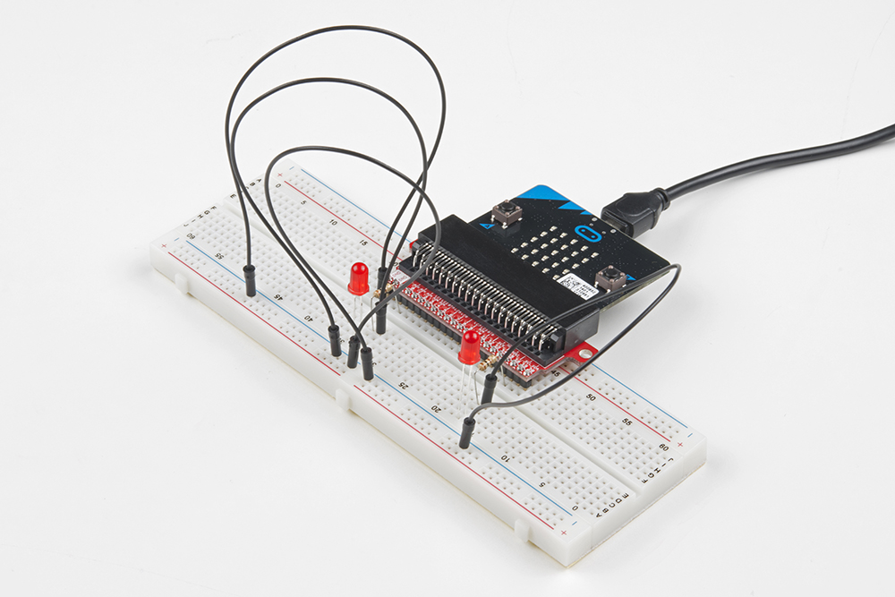
Ready to start hooking everything up? Check out the wiring diagram below to see how everything is connected.
| Polarized Components | Pay special attention to the component’s markings indicating how to place it on the breadboard. Polarized components can only be connected to a circuit in one direction. |
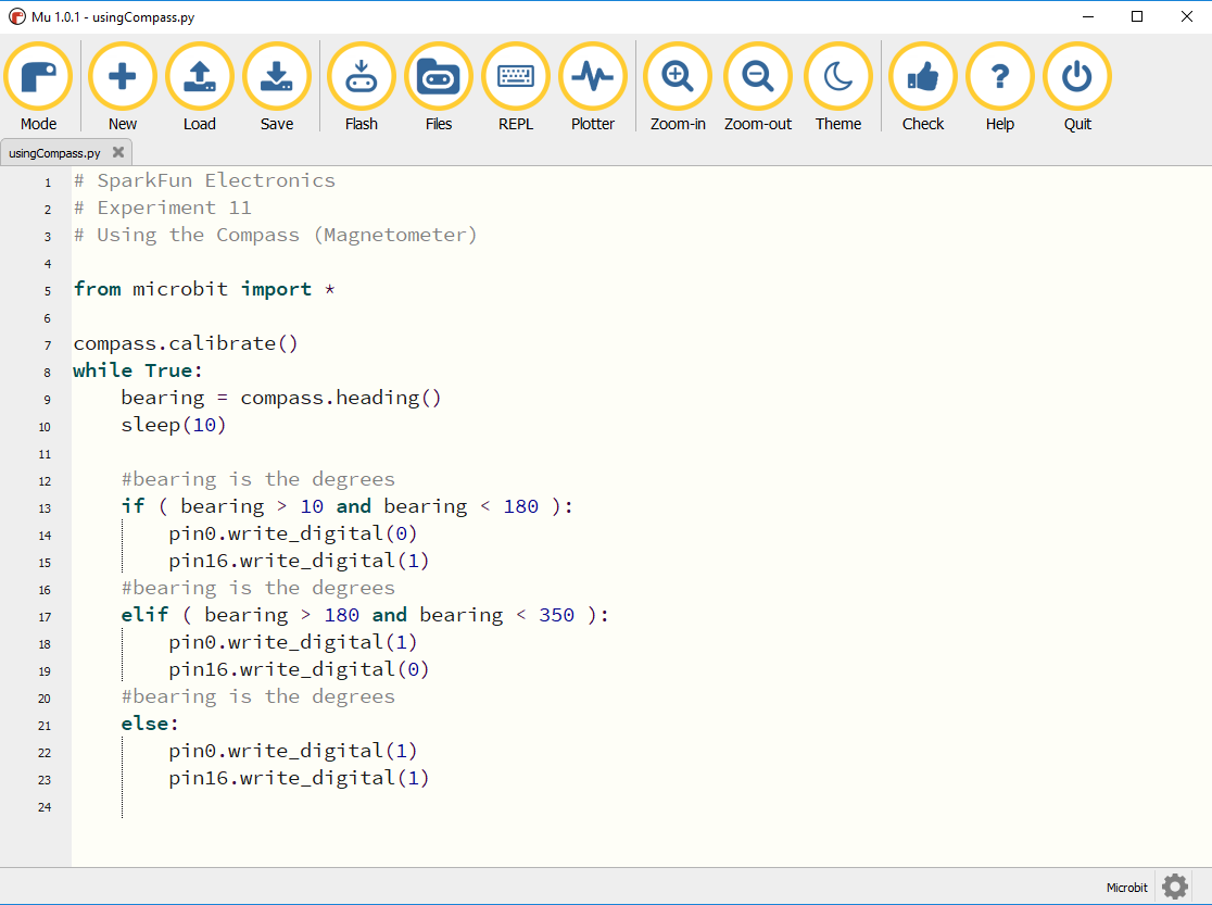
Let's read a magnetometer and light up a few LEDs . Type (or copy) the program into your Mu editor, or download all the programs from this GitHub Repository and open the Ex11_usingMag.py program. Save it, then click the Flash icon to program your micro:bit.
language:python
# SparkFun Electronics
# Experiment 11
# Using the Compass (Magnetometer)

from microbit import *

compass.calibrate()
while True:
    bearing = compass.heading()
    sleep(10)

    #bearing is the degrees
    if ( bearing > 10 and bearing < 180 ):
        pin0.write_digital(0)
        pin16.write_digital(1)
    #bearing is the degrees
    elif ( bearing > 180 and bearing < 350 ):
        pin0.write_digital(1)
        pin16.write_digital(0)
    #bearing is the degrees
    else:
        pin0.write_digital(1)
        pin16.write_digital(1)
Let's take a look at the code in this experiment.
The compass heading function returns the heading that you are facing if you are holding the micro:bit flat with the pins toward you. Zero degrees is north. We store this heading in a variable called bearing.
Much of the rest of this code is straightforward, but the logical and operator is used. This combines two logical statements into one statement that returns true when both of the other statements are true and only true.
When your code is loaded you will first see instructions on the micro:bit LED array. The instructions will ask you to tilt the micro:bit around until all of the LEDs on the micro:bit face have been lit up. Once this has been done, it will display a smiley face. This process is to calibrate the micro:bit's magnetometer with its surroundings. The LEDs will start to turn on --- one or the other, or both. While standing still, rotate in the direction of the LED that is on. When both LEDs are lit, you are facing generally north (if you are outside)! You now have a compass that helps you find north, or any other direction you choose if you change the code!
You may have a motor or magnet close by! The magnetometer is sensitive to all magnetic fields, including ones that may be produced by other electronics, metal, or even...a magnet.
You might have your logical statement backward! Try flipping your greater than to less than, or the other way around.
For more information about the micro:bit breakout board, check out the resources below:
MicroPython is a fun and exciting way to get started on your Python programming journey. Here are some more resources to help you along.
We produce a number of other kits and carrier boards that you can hook up to your micro:bit to help take your projects to the next level. Here is some further reading that may help you along in learning more about the world of electronics.
For more information on our micro:bit ecosystem, check out these tutorials:
learn.sparkfun.com | CC BY-SA 3.0 | SparkFun Electronics | Niwot, Colorado