FemtoBuck Constant Current LED Driver Hookup Guide v13
 SFUptownMaker
 Introduction
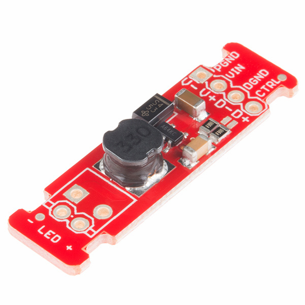
The FemtoBuck is a small-size, single-output constant current LED driver. By default, the FemtoBuck is driven at 330mA. That current can be reduced by either presenting an analog voltage or a PWM signal to the board. It can be increased to 660mA by closing a solder jumper on the board, as described later in this tutorial.
Suggested Reading
Here are some topics you should know before using the FemtoBuck. Have a look if you need more information.
Voltage, Current, Resistance, and Ohm's Law
Pulse Width Modulation
Resistors
Light-Emitting Diodes (LEDs)
Electric Power
FemtoBuck Overview
Connecting the FemtoBuck
For the version 1.2 of the FemtoBuck, we've increased the voltage ratings on the parts to allow the input voltage to cover the full 36V range of the AL8860. Note that the supply voltage must be at least 6.0V, and should be at least 2-3V higher than the forward voltage of the LED(s) to be driven. You can use the board to drive any high power LED like the ones listed below. Keep in mind that you would need 3x FemtoBucks to control each channel on the triple output high power RGB LED.
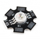
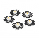
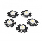
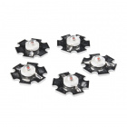
LED - 3W Aluminum PCB (5 Pack, Red)
COM-13106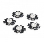
LED - 3W Aluminum PCB (5 Pack, Blue)
COM-13107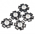
LED - 3W Aluminum PCB (5 Pack, Green)
COM-13185Since the FemtoBuck is a constant current driver, the current drawn from the supply will drop as supply voltage rises. In general, efficiency of the FemtoBuck is around 95%, depending on the input voltage.
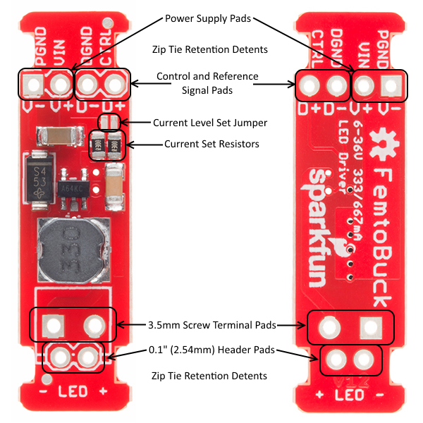
One signal input is provided for dimming control. A ground pin (DGND) is provided to reference against the controlling module for accuracy. Dimming can be done by an analog voltage (20%-100% of max current by varying voltage from .5V-2.5V) or by PWM (so long as PWM minimum voltage is less than .4V and maximum voltage is more than 2.4V) for a full 0-100% range.
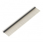
Another ground (PGND) pin is available next to the power supply pin to provide a high-current return path. The spacing on the four holes on the input side is 0.1" for standard headers.

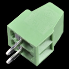
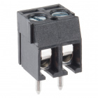
The output side has a 0.1" spaced hole pair as well as a 3.5mm spaced hole pair, to allow the user to attach our 3.5mm screw terminals.
The notches on either end of the board allow you to use a zip tie to secure the wires to the board after soldering them down.
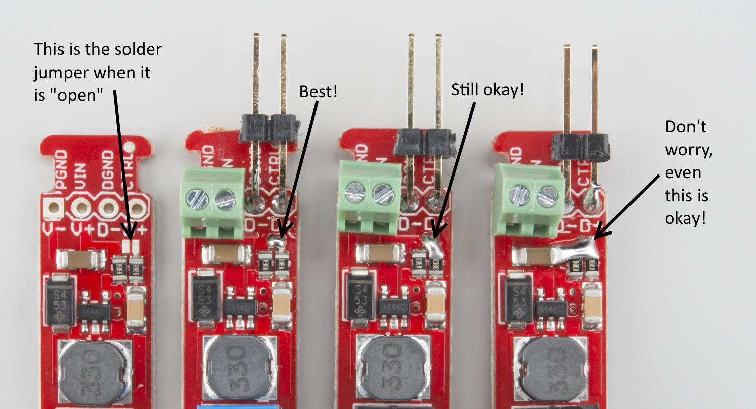
The most recent revision has a small solder jumper, highlighted above, that can be closed with a glob of solder to double the output current from 330mA to 660mA. We suggest closing this jumper before soldering headers, terminals, or wires to the nearby holes. Note that it's very likely that you'll get some solder on the adjacent resistor pads. That's perfectly okay. Those pads will be shorted together when you're done anyway.
Finally, take note of the size of the FemtoBuck. If desired, the entire board can be slid into a piece of 9mm heat shrink tubing to provide insulation and strain relief.

Connecting to an Arduino or Compatible Board
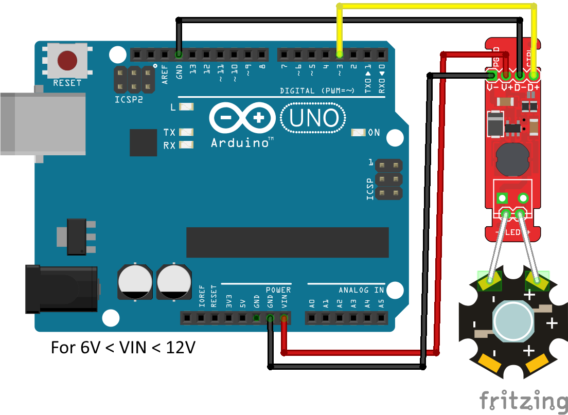
If you have only one or two LEDs, you can connect the FemtoBuck directly to the VIN pin on your Arduino. You will need to power the board from an external supply, as the 5V provided by USB isn't high enough to power the FemtoBuck (the FemtoBuck won't turn on below 6V).
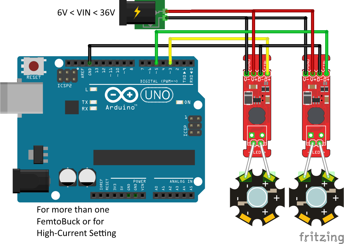
If you want more than one FemtoBuck, or if you've closed the solder jumper to increase the drive current, you'll need to add an external power supply. It's not good to try to run too much current through the traces on the Arduino. Note that the LEDs are wired separately to each FemtoBuck! This is very important; the output of each FemtoBuck must be completely isolated from any other! That means that RGB LEDs with "common" pins (common anode or common cathode) cannot be used with the FemtoBuck!
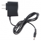
Wall Adapter Power Supply - 9VDC 650mA
TOL-00298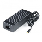
Power Supply - 24V (5A)
TOL-13758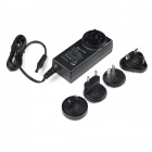
Multiple LEDs can be connected in series, as shown, and the supply voltage should be at least 2-3V higher than the sum of the forward voltages of the LEDs.
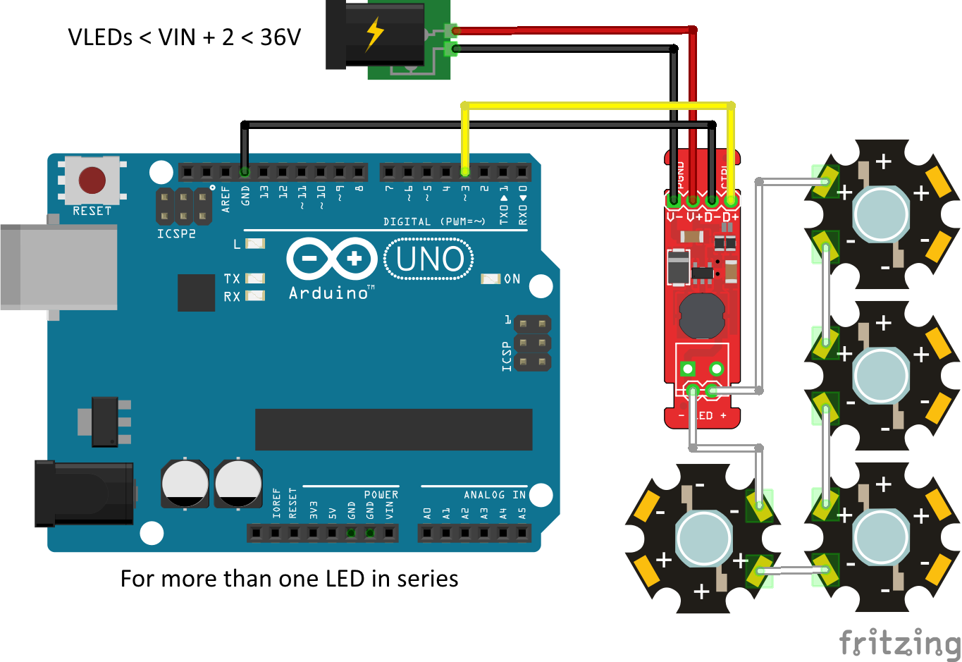
For instance, our blue 3W LEDs have a forward voltage of 3.2V to 3.8V. To be on the safe side, use the highest voltage in the range. If you want to connect four of them, you'd need a power supply of ~17V or greater (3.8V + 3.8V + 3.8V + 3.8V = 15.2V; add 2V of "head room").
Since 17V is greater than the Arduino can tolerate on its input, we have to provide an external supply for the Arduino as well. This can be the standard 5V USB supply.
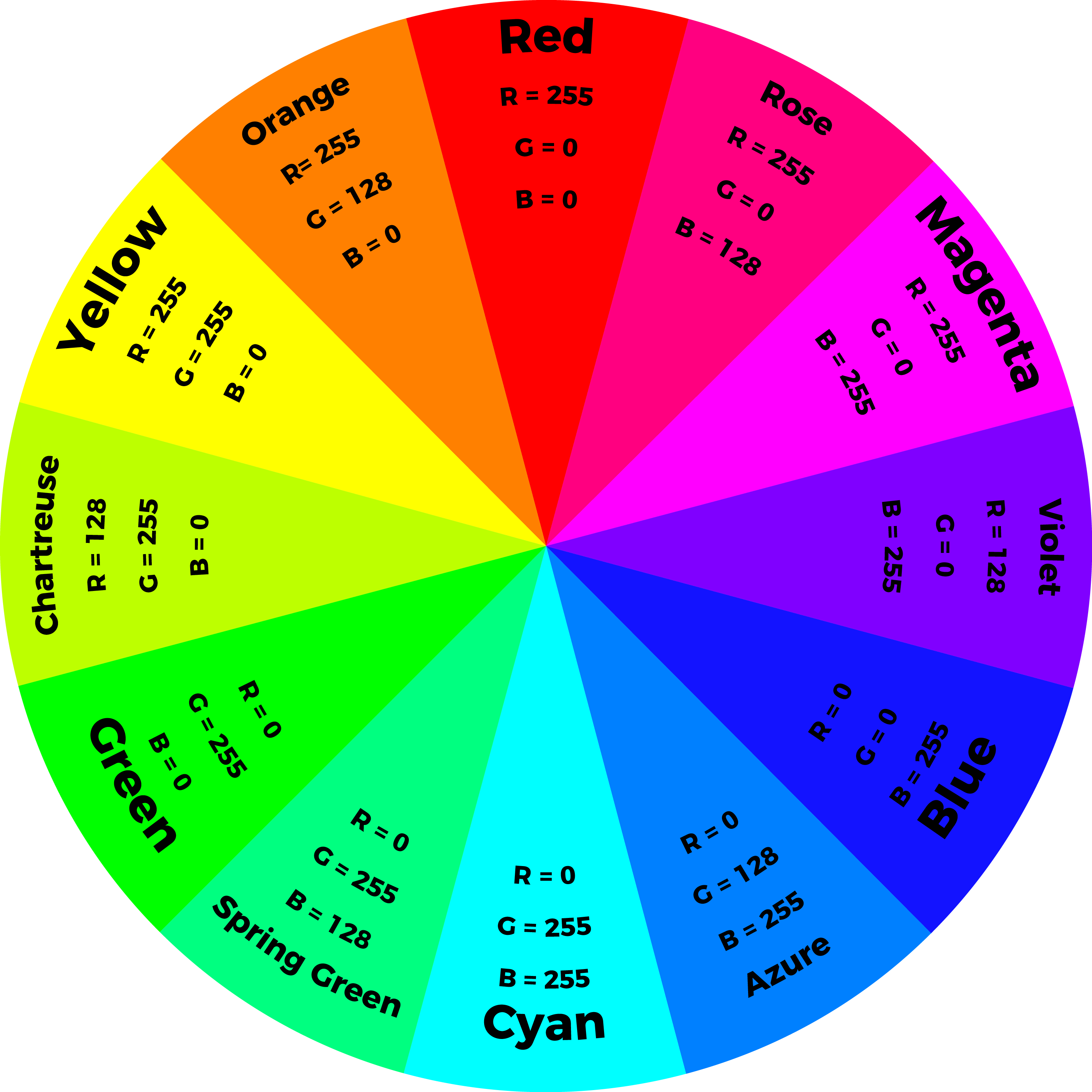
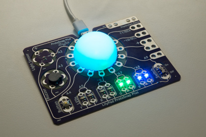
Try checking the example that was used in the LilyPad ProtoSnap Plus Activity Guide for custom color mixing with tertiary colors. Just make sure to update the pin definitions.
Or try using the code from the Non-Addressable RGB LED Strip Hookup Guide. While the code was written for RGB strips with transistors, the code functions the same with the the PickBuck.
Non-Addressable RGB LED Strip Hookup Guide
Further Increasing Current Drive Strength
If even 660mA isn't enough current for you, it is possible to increase the maximum current of the FemtoBuck board up to 1A per channel. To do so, replace the current sense resistors with smaller values. To calculate the new value for the resistor, use this formula:
Thus, for a 1A current, you'd want a 0.1Ω resistor. Don't forget to be wary of current ratings; at 1A, the sense resistor will be dissipating 1/10W, so you probably want a resistor of at least 1/8W rating. The package is a standard 0805.
Resources and Going Further
For more information about the FemtoBuck, take a look at the following resources:
- Schematic
- Eagle Files
- All About LEDs
- Datasheet (AL8860)
- GitHub (Design Files)
Consider checking out these other tutorials for more information about concepts in this guide:
- Light - Covers some useful concepts, such as why doubling the current doesn't appear to double the brightness.
- Diodes - Diodes are a slightly more complex beast than resistors. Our diodes tutorial will help you understand why we need a special device to power them.
- Pico Buck Hookup Guide - Need to control more LEDs? The PicoBuck is just like the FemtoBuck except it has three channels, each capable of providing 350mA. Perfect for controlling high powered RGB LEDS that require control of each color individually.
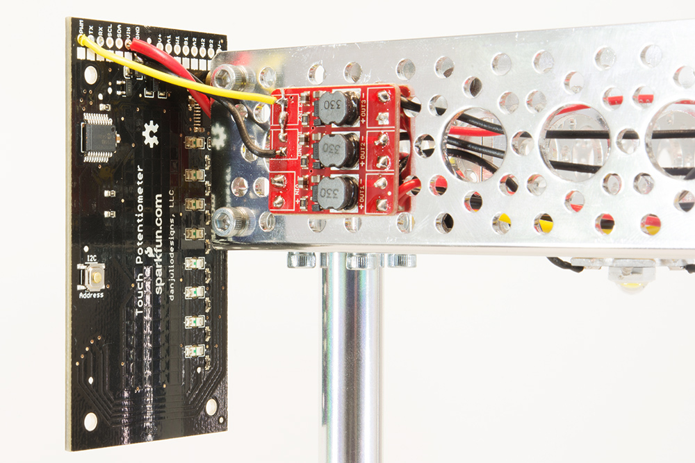
Need some inspiration for your next project? Check out the PWM Lighting Controller example used with the touch potentiometer:
Or maybe try using the FemtoBuck to do some LED home lighting.