ESP32 Thing Power Control Shield Hookup Guide
 Alex the Giant
Hardware Assembly
Soldering the pins
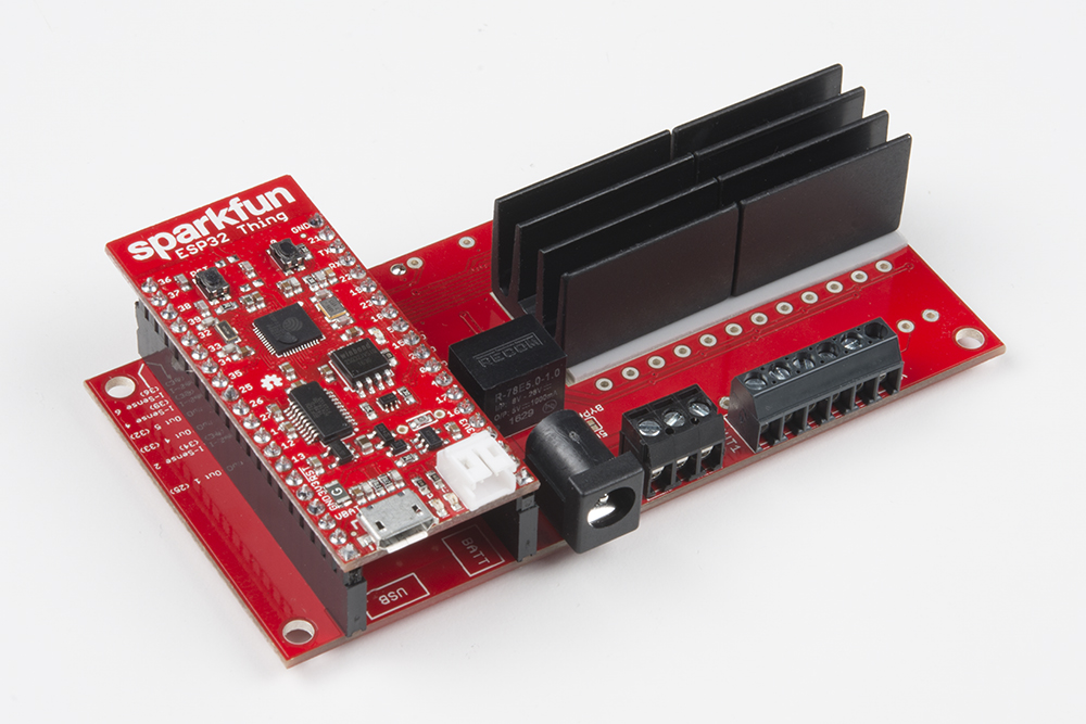
The first step in assembly is connecting the ESP32 Thing. Solder the male header pins from the top of the ESP32. Then solder the female header pins on the bottom side of the Power Control Shield. Make sure that the female header pin's sockets are facing out from the top side. The top side of the Power Control Shield will have the relay, barrel jack, and screw terminals. When connecting the ESP32, make sure to align it to the Power Control Shield's silkscreen for USB and BATT. These silk references correspond to the USB and battery connector on the ESP32 Thing. The correct orientation can be seen below after soldering the header pins.

Current Sense Gain
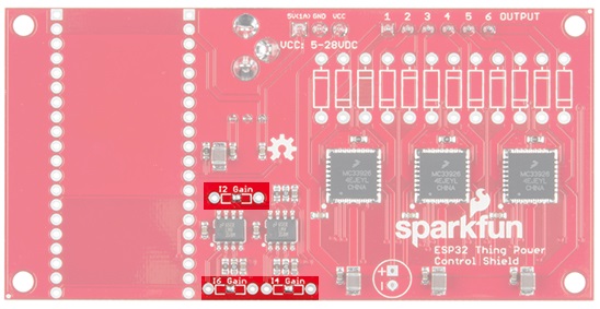
The MC33926 has a built in current sensor, which corresponds to 0.24% of the output current. Unfortunately, there is only one current sensor per driver which means current sensing is only supported on outputs 2, 4, and 6. For smaller loads, clearing the solder jumper with the iron and soldering in the appropriate feedback resistors for I2 gain, I4 gain, and I6 gain can maximize the sensitivity of the 12-bit analog to digital converter (ADC) built into the ESP32 Thing.
Use the table below for choosing the appropriate resistor values.
| Max Current (A) | Recommended Resistor (maximum value in Ω) |
|---|---|
| 5.0 | 2,800 |
| 4.5 | 4,300 |
| 4.0 | 6,200 |
| 3.5 | 8,800 |
| 3.0 | 12,200 |
| 2.5 | 17,300 |
| 2.0 | 24,800 |
| 1.5 | 38,500 |
| 1.0 | 69,000 |
| 0.5 | 238,000 |
Keeping the Drivers Cool
As VCC and the current draw increases, the driver ICs can get pretty hot due to the MOSFET’s resistance that do the actual switching between VCC and GND. MOSFETs are often described as switches. Unlike a normal switch, the resistance between the drain and source pins when the MOSFET is on, often referred to as Rds(on), is a bit higher than a mechanical switch (around 225 mΩ). It doesn't sound like much, but under full load the power that's wasted as heat can be as high as 5.6W! If your drivers are getting hot, add a heat sink to the back of the board like the image shown below.
If heat sinks aren't able to pull the heat away fast enough, you may also need a fan. If your supply voltage is 12V, a standard computer fan should work. If it's not and you don't want to use two supplies, the 5V rail has been broken on on 3-pin screw terminal for a 5V fan, and it is capable of sourcing up to 1A of current.
5V Bypass Jumper
A linear regulator (like the LM7805), can regulate any DC voltage from 7 to 35V down to 5V. If your supply drops below 7V, the output voltage will follow the input voltage up to 5V. To minimize the heat dissipation, a high efficiency DC-DC converter was used on the Power Control Shield to regulate the supply voltage down to 5V for powering the ESP32 Thing. Unfortunately, the output from the DC-DC converter will not turn on like a linear regulator if the input voltage drops below the minimum voltage. With the ESP32 Thing Power Control Shield, that minimum voltage of 7V and any voltage under that is not guaranteed to be sufficient for providing power to the ESP32.
What if the load needs to be at 5V? In that case, you should use the 5V bypass jumper that is shown in the image below.
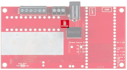
When soldered closed, the jumper shorts the VCC and 5V power rails together, allowing you to bypass the regulator and power the ESP32.
Slew Rate
The slew rate jumper on the top of the board has two configurations to control how fast the output pins switch between on and off. The default mode has the solder jumper set to SLOW and it typically takes 3.0 us to switch states. You can cut the trace and add a solder jumper to switch to FAST mode. When the board is set to FAST, it can switch the state anywhere from 0.2 us to 1.45 us. If you are not using an inductive load (such as a motor), the default slow slew will create smaller current spikes when the load switches on or off.

The Unpopulated Parts
You may have noticed that there are quite a few unpopulated through hole parts on the board. The first three to mention are the resistors labeled I2 Gain, I4 Gain, and I6 Gain. These are the feedback resistors used in the non-inverting op-amps circuits that are discussed in detail in the Current Sense Gain section above.
Next is the capacitor connected to VCC and GND. As inductive loads (such as motors) turn on, there is a large current spike to charge the coils which can pull the supply voltage low enough that the power supply to the ESP32 Thing shuts off which can cause the microcontroller to reset. To keep the input voltage steady, you can add a large capacitor. The right capacitor depends on the size of the load, but any electrolytic capacitor larger than 100 μF should help. The pin spacing should be 2.5 mm, and the voltage rating should be at least the same as your supply voltage. Although, it's good practice to use parts that are rated for 1.5 times the voltage you expect.

Lastly, there are 12 unpopulated diodes that are connected to either VCC or GND, and the output pins. The diode footprints are there for people that are planning on using inductive loads. As an inductor discharges, there can be a large voltage spike. If the spike is large enough, it can possibly damage the MC33926 driver. For that reason, it's recommended to pick up and install 12 of our 1N5819 or 1N4001 diodes.