ESP32-S2 Thing Plus Hookup Guide
Hardware Overview
Board Dimensions
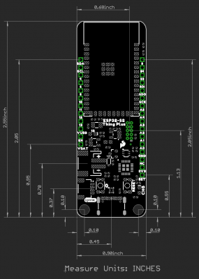
The board dimensions are illustrated in the drawing below. The listed measurements are in inches and the two mounting holes are compatible with 4-40 standoff screws.
USB-C Connector
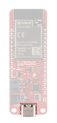
The USB connector is provided to power and program the board. For most users, it will be the primary programing interface for the ESP32-S2.
TC7USB40MU USB Switch
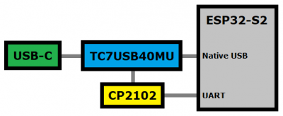
The TC7USB40MU is used to switch the data lines for the USB-C connection, between the ESP32-S2 module's native USB pins or its UART pins, through a CP2102 Serial-to-UART bridge. There is a jumper on the back of the board to control the USB switch; by default, the data lines from the USB-C connector are tied to the CP2102 Serial-to-UART bridge.
CP2102 Serial-to-UART
The CP2102 allows the ESP32-S2 to communicate with a computer/host device through its USB-C connection. This allows the board to show up as a device on the serial (or COM) port of the computer. Users will need to install the latest drivers for the computer to recognize the board (see Software Overview section).
Power
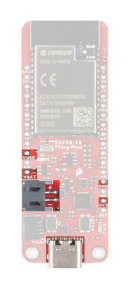
The ESP32-S2 Thing Plus only requires 3.3V to power the board. However, the simplest method to power the board is with the USB-C connector. There are additional power pins available on the board:
- 3.3V - A regulated 3.3V voltage source.
- Regulated from the USB 5V power and/or battery connection.
- Used to power the ESP32-S2 module and Qwiic I2C bus.
- USB - The voltage from the USB-C connector, usually 5V.
- VBAT - The voltage from the JST battery connector; meant for single cell LiPo batteries.
- GND - The common ground or the 0V reference for the voltage supplies.
Charging Circuit
The charging circuit utilizes the MCP73831 linear charge management controller and is powered directly from the USB-C connector or USB. The controller is configured for a 500mA charge rate by default; there is a jumper on the back of the boards for users to lower the charge rate to 100mA. Battery charging is indicated when the yellow, CHG LED. If the charge controller is shutdown or charging is complete, the CHG LED will turn off. For more information, please refer to the MCP73831 datasheet.
ESP32-S2 Module
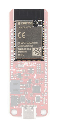
The ESP32-S2 WROOM module from Espressif is the brains of the ESP32-S2 Thing Plus. While the new ESP32-S2 module does include improved security features to addresses the security flaws in the original ESP32, it lacks the Bluetooth capabilities of the original module. For more details check out the datasheets for the ESP32-S2 chipset and the ESP32-S2 WROOM module.
- Xtensa® Single-Core 32-bit LX7 Microprocessor (up to 240MHz)
- RISC-V ULP Coprocessor
- 128KB ROM and 320KB SRAM
- 4MB of Embedded SPI Flash Storage
- Cryptographic Hardware Accelerators
- AES, ECB/CBC/OFB/CFB/CTR, GCM, SHA, RSA, and ECC (Digital Signature)
- Physical Security Features
- Transparent external flash and RAM encryption (AES-XTS)
- Secure Boot feature ensures only signed firmware (with RSA-PSS signature) is booted
- HMAC and Digital Signature modules use software inaccessible keys to generate SHA-MAC and MAC signatures
- Integrated 802.11 b/g/n WiFi 2.4GHz Transceiver (up to 150Mbps)
- Integrated Temperature Sensor (-20°C to 110°C)
- 34 GPIO (excluding strapping pins)
- 1x USB OTG Interface
- 1x DVP Camera Interface
- 1x LCD Interface
- Operating Voltage: 3.0 to 3.6V
- WiFi: 310mA (peak)
- Light-Sleep: 550µA
- Deep-Sleep: 20-235µA
Note: Users should be aware of the following nuances and details of this board
- The ESP32-S2 is only compatible with 2.4GHz WiFi networks; it will not work on the 5GHz bands.
- Users interested in the AES-XTS RAM encryption feature, will need to use the Espressif IDF. For more information, check out section 3.1.3 External Flash and RAM of the ESP32-S2 chipset datasheet.
- For details on the boot mode configuration, please refer to section 3.3 Strapping Pins of the ESP32-S2 WROOM module datasheet. By default,
IO46uses an internal pull-down resistor.
Note: While most users will utilize the USB connection for serial programming, the ESP32-S2 can also be programmed through its JTAG or SWD pins. This might is useful for individuals developing and debugging firmware that would be flashed directly onto the module, such as in production for commercial applications.
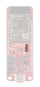
The JTAG pins on the ESP32-S2 Thing Plus. (Click to enlarge)
Users can also utilize the ESP32-S2 as a JTAG bridge; check out the project from Espressif for more information.
Peripherals and I/O
Note: Users should be aware of the following nuances of this board
- ⚡ All the GPIO on the ESP32-S2 Thing Plus are 3.3V pins.
- ⚡ There are electrical limitations to the amount of current that the ESP32-S2 module can sink or source. For more details, check out the ESP32-S2 WROOM module datasheet.
- ⚡ There is a pullup resistor on
IO18on pinA1. For more details, check out the Note following Fig. 6 in the Peripheral Schematics section of the ESP32-S2 WROOM module datasheet. - There are some limitations to the ADC performance, see the Note from the ADC Characteristics section of the ESP32-S2 WROOM module datasheet.
- The
ENpin is used to contol the ESP32-S2 chip. - High: On - enables the chip.
- Low: Off - the chip powers off.
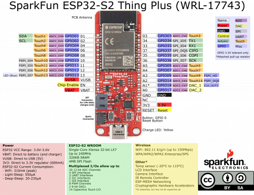
The pins from the ESP32-S2 module are broken out into a feather form factor layout. There are 21 I/O pins broken out on this board, with 8 I/O pads on the back of the board. All of the ESP32-S2 Thing Plus pins are broken out with .1" pitch spacing for headers. With the ESP32's pin multiplexing, various pins will be capable of several functionalities. For more technical specifications on the I/O pins, you can refer to the ESP32-S2 datasheet.
- 16x 12-bit ADC Channels
- 2x 8-bit DAC
- 14x Capacitive Touch Sensing
- 4x SPI (only one is configured by default in the Arduino IDE)
- 1x I2S
- 2x I2C (only one is configured by default in the Arduino IDE)
- 2x UART (both are configured by default in the Arduino IDE, but one UART is used for bootloading/debug)
- 8x PWM Channels
- 1x DVP Camera Interface
- 1x LCD Interface
Note: Users should be aware of the following limitations for the board in the Arduino IDE.
- Not all of the features, listed above, are available in the Arduino IDE. For the full capabilities of the ESP32-S2, the Espressif IDF should be utilized.
- Only one I2C bus is defined.
- Only two UART interfaces are available.
- UART (USB):
Serial RX1/TX1Pins:Serial1- Only one SPI bus is defined.
- The bit-width for the ADC2 channels needs to be set when reading ADC values.
- Setting the bit-width before taking any ADC readings doesn't work; the bit-width must be set, when the making ADC readings.
- The example code below, properly demonstrates how to read values from the ADC2 channels.
Buttons
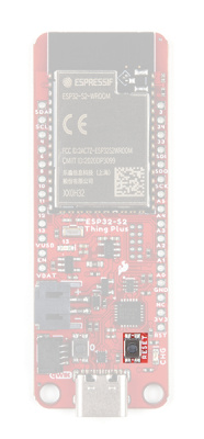
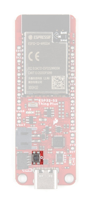
There are two buttons on ESP32-S2 Thing Plus; a Reset and IO0 button.
Reset Button
The reset (RST) button allows users to reset the program running on the ESP32-S2 module without unplugging the board.
User Button
Note: In order to utilize the user button, connected to IO 0, the pin mode will need to be configured as an input with an internal pullup (i.e. INPUT_PULLUP); see an example below.
pinMode(D0, INPUT_PULLUP);
The user (0 ) button allows users to short IO 0 to ground (GND).
IO 0 button on the ESP32-S2 Thing Plus. (Click to enlarge) Indicator LEDs
There are two indicator LEDs on the ESP32-S2 Thing Plus:
- Status/Pin 13 (Blue)
- Battery Charging (Yellow)
Battery Charging LED
The yellow, CHG LED will light while a battery is being charged through the charging circuit. The LED will be off when no battery is present (*dimmed), when the charge management controller is in standby (after the battery charging has been completed), or when the charge management controller is shutdown. The LED will be on when the charge management controller is in the process of charging the battery. For more information, please refer to the MCP73831 datasheet.
| Charge Cycle State | STAT1 |
|---|---|
Shutdown
|
Off (High Z) |
| No Battery Present | Dimmed (High Z) |
| Charge Complete – Standby | Off (H) |
| Preconditioning | On (L) |
| Constant-Current Fast Charge | On (L) |
| Constant Voltage | On (L) |
STAT LED
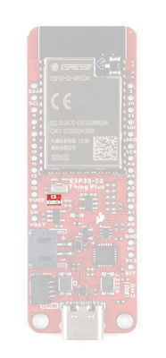
The blue, status (13) LED is typically used as a test or status LED to make sure that a board is working or for basic debugging. This indicator is connected to GPIO 18.
13) LED indicator on the ESP32-S2 Thing Plus. (Click to enlarge) Jumpers
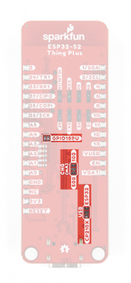
There are three jumpers on the back of the board that can be used to easily modify the hardware connections on the board.
- USB - This jumper can be used to control the USB-C data line connections through the TC7USB40MU USB switch.
- By default, the data lines are connected to the CP2102 Serial-to-UART bridge; and therefore, tied to the ESP32-S2's UART pins.
- CHG - This jumper can be used to modify the charging rate to the LiPo JST connector.
- By default, the charge rate is configured to 500mA.
- GPIO18PU - This jumper can be used to disconnect the pull-up resistor on
GPIO18.
Never modified a jumper before? Check out our Jumper Pads and PCB Traces tutorial for a quick introduction!
How to Work with Jumper Pads and PCB Traces
Primary I2C Bus
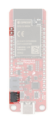
The Qwiic connector is attached to the primary I2C bus. The primary I2C bus for this board utilizes the pin connections, detailed in the table below:
| Connection | VDD |
GND |
SCL |
SDA |
|---|---|---|---|---|
|
Pad Number
(ESP32-S2 module) |
3.3V | GND | IO2 |
IO1 |
Qwiic Connector
A Qwiic connector is provided for users to seamlessly integrate with SparkFun's Qwiic Ecosystem.
What is Qwiic?
The Qwiic system is intended a quick, hassle-free cabling/connector system for I2C devices. Qwiic is actually a play on words between "quick" and I2C or "iic".
Features of the Qwiic System
Keep your soldering iron at bay.
Cables plug easily between boards making quick work of setting up a new prototype. We currently offer three different lengths of Qwiic cables as well as a breadboard friendly cable to connect any Qwiic enabled board to anything else. Initially you may need to solder headers onto the shield to connect your platform to the Qwiic system but once that’s done it’s plug and go!
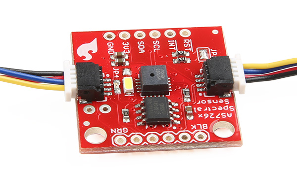
Qwiic cables connected to Spectral Sensor Breakout
Minimize your mistakes.
How many times have you swapped the SDA and SCL wires on your breadboard hoping the sensor will start working? The Qwiic connector is polarized so you know you’ll have it wired correctly, every time, from the start.
The PCB connector is part number SM04B-SRSS (Datasheet) or equivalent. The mating connector used on cables is part number SHR04V-S-B or equivalent. This is a common and low cost connector.
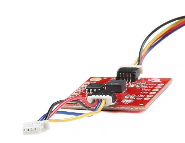
1mm pitch, 4-pin JST connector
Expand with ease.
It’s time to leverage the power of the I2C bus! Most Qwiic boards will have two or more connectors on them allowing multiple devices to be connected.
