$24.50
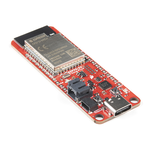
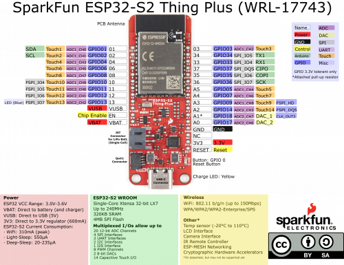
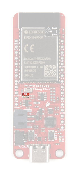
The ESP32-S2 Thing Plus is a feather form-factor development board with the improved ESP32-S2 module, from Espressif. The new ESP32-S2 module addresses the security flaws in the original ESP32. While the ESP32-S2 does include improved security features, it lacks the Bluetooth capabilities of the original ESP32 module.
Not Yet Implemented: The Arduino core for the ESP32 microcontroller are still a work in progress. There are a handful of peripherals and features that have yet to be implemented, including:
analogWrite([pin], [value]))
The peripherals are available (if, also, still in their infancy) in the IoT Development Framework for the ESP32. If your application requires any of the features above, consider giving the ESP-IDF a try! (Updated: June 2022.)
To get started, users will need a few items. Now some users may have a few of these items, feel free to modify your cart accordingly.
Headers Batteries Jumper Modification JTAG Functionality
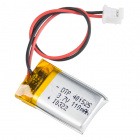
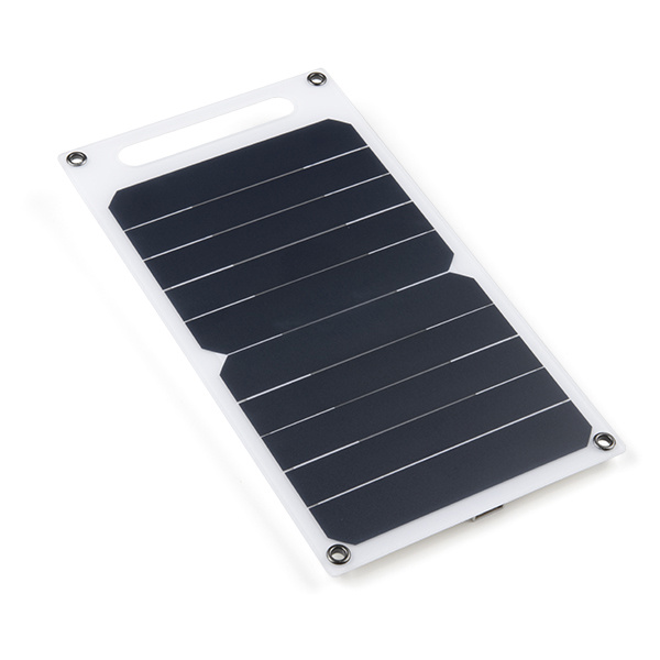
For mobile applications, users will want to pick up a single-cell LiPo battery from our catalog. Below, are a few available options:

To modify the jumpers, users will need soldering equipment and/or a knife.

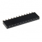
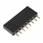
Headers are great for development purposes, letting users swap parts with just a set of jumper wires. If you would like to add headers to your board, check out some of the options for the Thing Plus or Feather form factor boards below. For a full selection of our available Headers or Soldering Tools, click on the associated links.

New to soldering? Check out our Through-Hole Soldering Tutorial for a quick introduction!
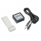
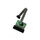
Users interested in JTAG applications (i.e. programming and debugging the ESP32) will need an JTAG Programmer and need to solder on a JTAG header. We recommend these programmers from our catalog:
As a more professionally oriented product, we will skip over the more fundamental tutorials (i.e. Ohm's Law and What is Electricity?). However, below are a few tutorials that may help users familiarize themselves with various aspects of the board.
One of the new, advanced features of the board is that it takes advantage of the Qwiic connect system. We recommend familiarizing yourself with the Logic Levels and I2C tutorials. Click on the banner above to learn more about Qwiic products.
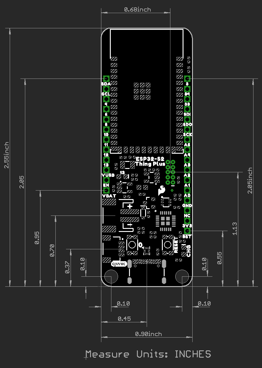
The board dimensions are illustrated in the drawing below. The listed measurements are in inches and the two mounting holes are compatible with 4-40 standoff screws.
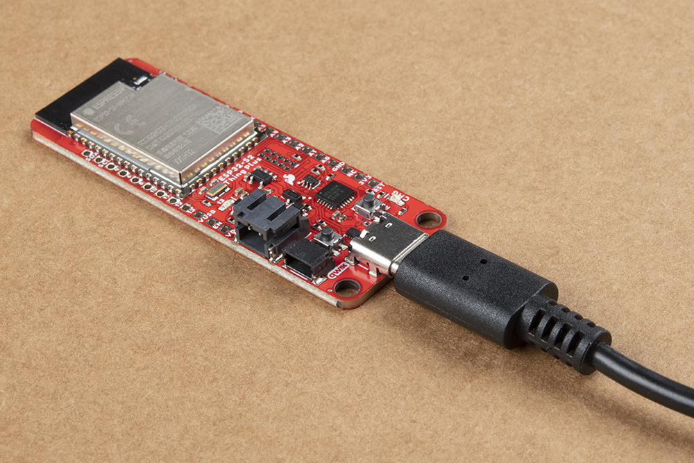
The USB connector is provided to power and program the board. For most users, it will be the primary programing interface for the ESP32-S2.
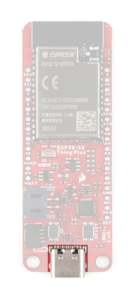
The TC7USB40MU is used to switch the data lines for the USB-C connection, between the ESP32-S2 module's native USB pins or its UART pins, through a CP2102 Serial-to-UART bridge. There is a jumper on the back of the board to control the USB switch; by default, the data lines from the USB-C connector are tied to the CP2102 Serial-to-UART bridge.
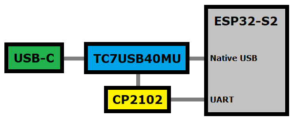
The CP2102 allows the ESP32-S2 to communicate with a computer/host device through its USB-C connection. This allows the board to show up as a device on the serial (or COM) port of the computer. Users will need to install the latest drivers for the computer to recognize the board (see Software Overview section).
The ESP32-S2 Thing Plus only requires 3.3V to power the board. However, the simplest method to power the board is with the USB-C connector. There are additional power pins available on the board:
The charging circuit utilizes the MCP73831 linear charge management controller and is powered directly from the USB-C connector or USB. The controller is configured for a 500mA charge rate by default; there is a jumper on the back of the boards for users to lower the charge rate to 100mA. Battery charging is indicated when the yellow, CHG LED. If the charge controller is shutdown or charging is complete, the CHG LED will turn off. For more information, please refer to the MCP73831 datasheet.
The ESP32-S2 WROOM module from Espressif is the brains of the ESP32-S2 Thing Plus. While the new ESP32-S2 module does include improved security features to addresses the security flaws in the original ESP32, it lacks the Bluetooth capabilities of the original module. For more details check out the datasheets for the ESP32-S2 chipset and the ESP32-S2 WROOM module.
Note: Users should be aware of the following nuances and details of this board
IO46 uses an internal pull-down resistor.Note: While most users will utilize the USB connection for serial programming, the ESP32-S2 can also be programmed through its JTAG or SWD pins. This might is useful for individuals developing and debugging firmware that would be flashed directly onto the module, such as in production for commercial applications.
Users can also utilize the ESP32-S2 as a JTAG bridge; check out the project from Espressif for more information.
Note: Users should be aware of the following nuances of this board
IO18 on pin A1. For more details, check out the Note following Fig. 6 in the Peripheral Schematics section of the ESP32-S2 WROOM module datasheet.EN pin is used to contol the ESP32-S2 chip.The pins from the ESP32-S2 module are broken out into a feather form factor layout. There are 21 I/O pins broken out on this board, with 8 I/O pads on the back of the board. All of the ESP32-S2 Thing Plus pins are broken out with .1" pitch spacing for headers. With the ESP32's pin multiplexing, various pins will be capable of several functionalities. For more technical specifications on the I/O pins, you can refer to the ESP32-S2 datasheet.
Note: Users should be aware of the following limitations for the board in the Arduino IDE.
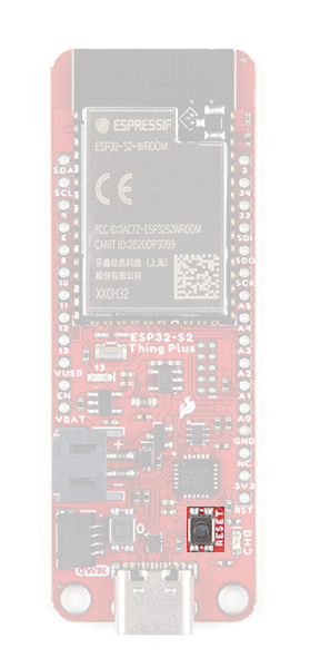
SerialRX1/TX1 Pins: Serial1There are two buttons on ESP32-S2 Thing Plus; a Reset and IO0 button.
The reset (RST) button allows users to reset the program running on the ESP32-S2 module without unplugging the board.
Note: In order to utilize the user button, connected to IO 0, the pin mode will need to be configured as an input with an internal pullup (i.e. INPUT_PULLUP); see an example below.
pinMode(D0, INPUT_PULLUP);
The user (0 ) button allows users to short IO 0 to ground (GND).
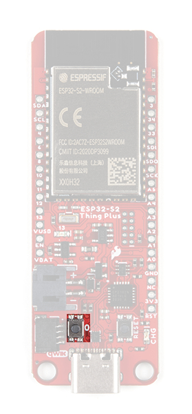
IO 0 button on the ESP32-S2 Thing Plus. (Click to enlarge) There are two indicator LEDs on the ESP32-S2 Thing Plus:
The yellow, CHG LED will light while a battery is being charged through the charging circuit. The LED will be off when no battery is present (*dimmed), when the charge management controller is in standby (after the battery charging has been completed), or when the charge management controller is shutdown. The LED will be on when the charge management controller is in the process of charging the battery. For more information, please refer to the MCP73831 datasheet.
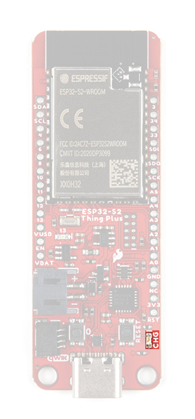
CHG) LED indicator on the ESP32-S2 Thing Plus. (Click to enlarge)
| Charge Cycle State | STAT1 |
|---|---|
Shutdown
|
Off (High Z) |
| No Battery Present | Dimmed (High Z) |
| Charge Complete – Standby | Off (H) |
| Preconditioning | On (L) |
| Constant-Current Fast Charge | On (L) |
| Constant Voltage | On (L) |
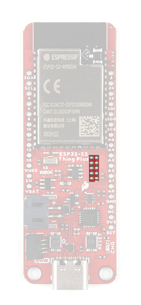
The blue, status (13) LED is typically used as a test or status LED to make sure that a board is working or for basic debugging. This indicator is connected to GPIO 18.
13) LED indicator on the ESP32-S2 Thing Plus. (Click to enlarge) There are three jumpers on the back of the board that can be used to easily modify the hardware connections on the board.
GPIO18.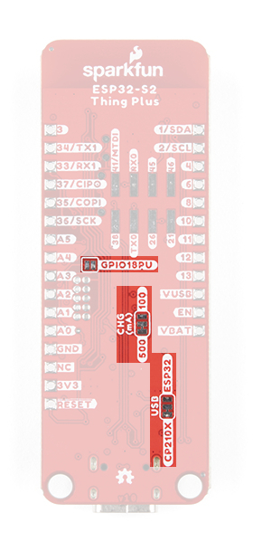
Never modified a jumper before? Check out our Jumper Pads and PCB Traces tutorial for a quick introduction!
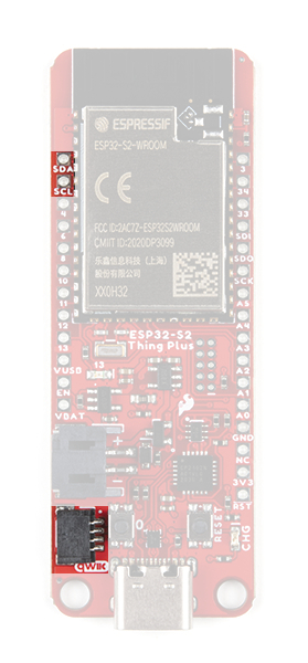
The Qwiic connector is attached to the primary I2C bus. The primary I2C bus for this board utilizes the pin connections, detailed in the table below:
| Connection | VDD |
GND |
SCL |
SDA |
|---|---|---|---|---|
|
Pad Number
(ESP32-S2 module) |
3.3V | GND | IO2 |
IO1 |
A Qwiic connector is provided for users to seamlessly integrate with SparkFun's Qwiic Ecosystem.
What is Qwiic?
The Qwiic system is intended a quick, hassle-free cabling/connector system for I2C devices. Qwiic is actually a play on words between "quick" and I2C or "iic".
Cables plug easily between boards making quick work of setting up a new prototype. We currently offer three different lengths of Qwiic cables as well as a breadboard friendly cable to connect any Qwiic enabled board to anything else. Initially you may need to solder headers onto the shield to connect your platform to the Qwiic system but once that’s done it’s plug and go!

Qwiic cables connected to Spectral Sensor Breakout
How many times have you swapped the SDA and SCL wires on your breadboard hoping the sensor will start working? The Qwiic connector is polarized so you know you’ll have it wired correctly, every time, from the start.
The PCB connector is part number SM04B-SRSS (Datasheet) or equivalent. The mating connector used on cables is part number SHR04V-S-B or equivalent. This is a common and low cost connector.

1mm pitch, 4-pin JST connector
It’s time to leverage the power of the I2C bus! Most Qwiic boards will have two or more connectors on them allowing multiple devices to be connected.
Users will need to install the SiLabs CP2104 Driver, which can be found here: USB to UART Bridge VCP Driver
Most users may already be familiar with the Arduino IDE and it's use. However, for those of you who have never heard the name Arduino before, feel free to check out the Arduino website. To get started with using the Arduino IDE, check out our tutorials below:
Install the latest ESP32 board definitions in the Arduino IDE.
Note: For more instructions, users can follow this tutorial on Installing Additional Cores provided by Arduino. Users will also need the .json file for the Espressif Arduino Core:
https://raw.githubusercontent.com/espressif/arduino-esp32/gh-pages/package_esp32_index.json
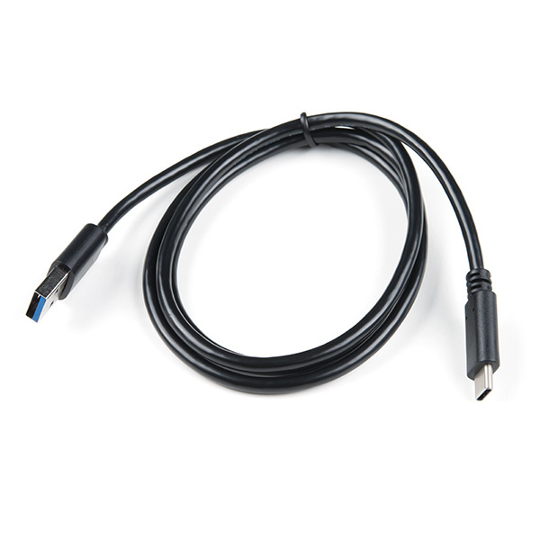
The USB connection is utilized for programming and serial communication. Users only need to plug their ESP32-S2 Thing Plus into a computer using a USB-C cable.
For remote IoT applications, a Li-Po battery can be connected. Additionally, users may be interested in utilizing a solar panel and USB-C cable to recharge their battery.
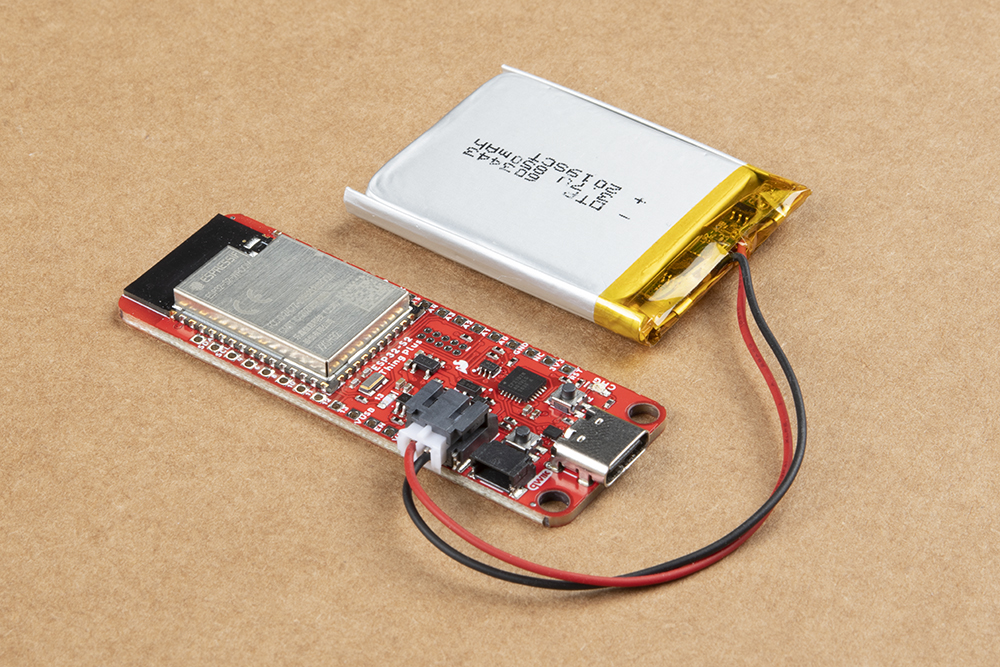
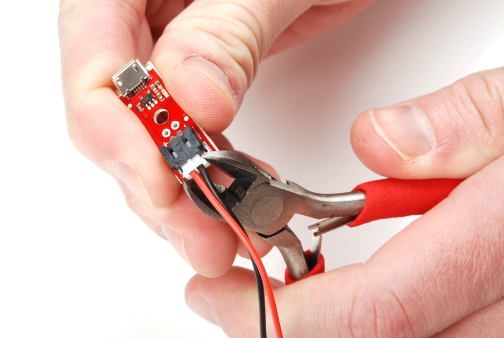
Note: DO NOT remove batteries by pulling on their wires. Instead, it is recommended that pair of dikes (i.e. diagonal wire cutters), pliers, or tweezers be used to pull on the JST connector housing, to avoid damaging the battery wiring.
The pins for the ESP32-S2 Thing Plus are broken out to 0.1"-spaced pins on the outer edges of the board. When selecting headers, be sure you are aware of the functionality you need. If you have never soldered before or need a quick refresher, check out our How to Solder: Through-Hole Soldering guide.
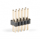
The Feather Stackable Header Kit is a great option as it allows users to stack shields (w/ Feather footprint) or it can be placed on the a breadboard; while, the pins are still accessible from the female/male headers.
The Qwiic system allows users to effortlessly prototype with a Qwiic compatible I2C device without soldering. Users can attach any Qwiic compatible sensor or board, with just a Qwiic cable. (*The example below, is for demonstration purposes and is not pertinent to the board functionality or this tutorial.)

To verify the toolchain and board are properly set up on their computer, users can upload the simplest of sketches -- Blink! The LED attached to GPIO 13 is perfect for this test. Plus, with the ESP32 attached to your computer, this is a good time to test out serial communication. Copy and paste the example sketch below into a fresh Arduino sketch:
language:c
int ledPin = 13;

void setup()
{
    pinMode(ledPin, OUTPUT);
    Serial.begin(115200);
}

void loop()
{
    Serial.println("Hello, world!");
    digitalWrite(ledPin, HIGH);
    delay(500);
    digitalWrite(ledPin, LOW);
    delay(500);
}
With everything setup correctly, upload the code! Once the code finishes transferring, open the serial monitor and set the baud rate to 115200. Users should see Hello, world!'s begin to fly by.
RESET button to get your ESP32-S2 Thing Plus to begin running the sketch.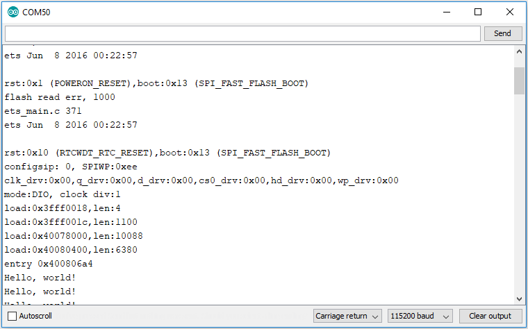
When the ESP32 boots up, it prints out a long sequence of debug messages. These are emitted every time the chip resets -- always at 115200 baud.
The ESP32 Arduino core includes a handful of WiFi examples, which demonstrate everything from scanning for nearby networks to sending data to a client server. Users can find the examples under the File > Examples > WiFi menu.
Here's another example using the WiFi library, which demonstrates how to connect to a nearby WiFi network and poll a remote domain (http://example.com/) as a client.
language:c
#include <WiFi.h>

// WiFi network name and password:
const char * networkName = "YOUR_NETWORK_HERE";
const char * networkPswd = "YOUR_PASSWORD_HERE";

// Internet domain to request from:
const char * hostDomain = "example.com";
const int hostPort = 80;

const int BUTTON_PIN = 0;
const int LED_PIN = 13;

void setup()
{
  // Initilize hardware:
  Serial.begin(115200);
  pinMode(BUTTON_PIN, INPUT_PULLUP);
  pinMode(LED_PIN, OUTPUT);

  // Connect to the WiFi network (see function below loop)
  connectToWiFi(networkName, networkPswd);

  digitalWrite(LED_PIN, LOW); // LED off
  Serial.print("Press button 0 to connect to ");
  Serial.println(hostDomain);
}

void loop()
{
  if (digitalRead(BUTTON_PIN) == LOW)
  { // Check if button has been pressed
    while (digitalRead(BUTTON_PIN) == LOW)
      ; // Wait for button to be released

    digitalWrite(LED_PIN, HIGH); // Turn on LED
    requestURL(hostDomain, hostPort); // Connect to server
    digitalWrite(LED_PIN, LOW); // Turn off LED
  }
}

void connectToWiFi(const char * ssid, const char * pwd)
{
  int ledState = 0;

  printLine();
  Serial.println("Connecting to WiFi network: " + String(ssid));

  WiFi.begin(ssid, pwd);

  while (WiFi.status() != WL_CONNECTED)
  {
    // Blink LED while we're connecting:
    digitalWrite(LED_PIN, ledState);
    ledState = (ledState + 1) % 2; // Flip ledState
    delay(500);
    Serial.print(".");
  }

  Serial.println();
  Serial.println("WiFi connected!");
  Serial.print("IP address: ");
  Serial.println(WiFi.localIP());
}

void requestURL(const char * host, uint8_t port)
{
  printLine();
  Serial.println("Connecting to domain: " + String(host));

  // Use WiFiClient class to create TCP connections
  WiFiClient client;
  if (!client.connect(host, port))
  {
    Serial.println("connection failed");
    return;
  }
  Serial.println("Connected!");
  printLine();

  // This will send the request to the server
  client.print((String)"GET / HTTP/1.1\r\n" +
               "Host: " + String(host) + "\r\n" +
               "Connection: close\r\n\r\n");
  unsigned long timeout = millis();
  while (client.available() == 0)
  {
    if (millis() - timeout > 5000)
    {
      Serial.println(">>> Client Timeout !");
      client.stop();
      return;
    }
  }

  // Read all the lines of the reply from server and print them to Serial
  while (client.available())
  {
    String line = client.readStringUntil('\r');
    Serial.print(line);
  }

  Serial.println();
  Serial.println("closing connection");
  client.stop();
}

void printLine()
{
  Serial.println();
  for (int i=0; i<30; i++)
    Serial.print("-");
  Serial.println();
}
Make sure to fill in the networkName and networkPswd variables with the name (or SSID) and password of your WiFi network! Then upload the code, open the Serial Monitor.
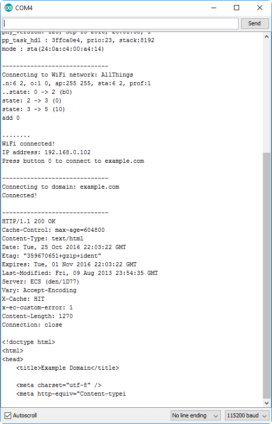
After the ESP32-S2 connects to the WiFi network, it will wait for users to press the 0 button. Tapping that will cause the ESP32 to make an HTTP request to example.com. You should see a string of HTTP headers and HTML similar to the screenshot above.
.json file needed for Epressif's ESP32 Arduino Core:
https://raw.githubusercontent.com/espressif/arduino-esp32/gh-pages/package_esp32_index.jsonFor more inspiration, check out these other ESP32 tutorials:
learn.sparkfun.com | CC BY-SA 3.0 | SparkFun Electronics | Niwot, Colorado