Driving Motors with Arduino
 bri_huang
 Introducing the transistor
Before we jump in, let's take a look at the transistor. We will only briefly show how the transistor works in this application. If you're interested in learning more, we have a full tutorial on transistors here.
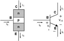
There are many different types of transistors; the one that we will be looking at is called an NPN BJT (Bi-Junction Transistor) transistor. The NPN describes the material properties of the device and how this devices behaves. (Note: There is also a PNP type transistor which works similarly but with different directions of current flow). A typical drawing or diagram of an NPN transistor looks like the image below.
Pin Labeling
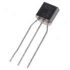
The three legs of the transistor are labeled Collector (C ), Base (B), and Emitter (E). Depending on the manufacturer and the package type, the order of these pins may differ. It's important to always double check the datasheets if you're not sure. There are two very common NPN transistors used with electronics. These are the 2N2222 and the BC337.
The pin labeling and orientation is the same for both the 2N2222 and the BC337. If you look at the top of a transistor, you'll notice that it has a shape of a capital letter D. There is one side that is curved and one side that is flat. Hold the transistor so that the pins are facing down and the flat edge faces to the left, the pins are in the same order as in the diagram above: Collector (top), Base (middle), and Emitter (bottom).
When looking at the schematic diagram for a transistor, the base is always in the middle; the emitter has an arrow pointing away (NPN transistors only), and the collector is the final un-marked pin.
How it works
Without going into too much depth on the nuances of semiconductors and quantum physics, here is a brief overview of how the NPN transistor functions. The transistor works like a switch. Imagine that there is a switch between the collector and the emitter. When the transistor is "off", the switch is open and current is not allowed to flow from the collector to the emitter. When the transistor is turned "on", the switch is closed and current flows from the collector to the emitter.
The base pin is used to control the transistor. When a voltage is applied to the base, the transistor turns on and current flows. The advantage of this configuration is that a low current signal from the Arduino can be used to turn the transistor on and off. The transistor works like a switch that can be used to close the circuit for a motor that is connected directly to the power supply.
Now, let's wire this up to our Arduino.