Driving Motors with Arduino
 bri_huang
Wiring up the circuit
Here is the schematic diagram for the circuit that we are going to wire up:
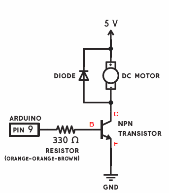
The transistor (switch) works in this circuit to close the circuit for the motor. One side of the motor is connected to 5V, the other is connected to the collector pin of the transistor, and the emitter is connected to ground. When a voltage is sensed at the base of the transistor, the transistor turns on, the switch is closed, closing the circuit for the motor circuit. Notice that the voltage for the motor comes directly from the 5V power supply.
Fly-back Diode
In this circuit, we also have a diode placed in parallel with the motor. Diodes only allow current to flow in one direction - as indicated by the arrow. This diode is often called a "fly-back" diode, and it helps to prevent damage to the transistor. As the motor starts and stops, the coils inside the motor can give create current spikes that may damage the transistor. This diode prevents that from happening.
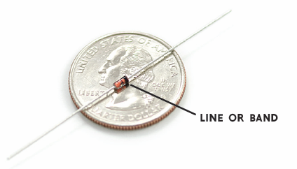
Most diodes have a line or a bar that marks one end of the device. This line corresponds the the line or bar on the end of the arrow in the diagram. In our circuit, this is connected to 5V.
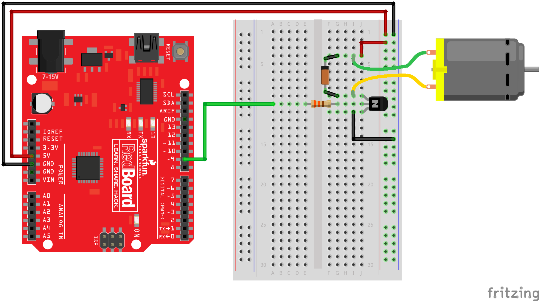
Final circuit
Here is the completed circuit as it should look like on your breadboard. Pay close attention to the direction of the diode. If it's plugged in backwards, you'll end up with unpredictable behavior. Notice that we are connecting one of the PWM pins (pin 9) on the Arduino to the base of the transistor. This will be our control signal for the motor.
Now you have your circuit, let's try out some sample code.