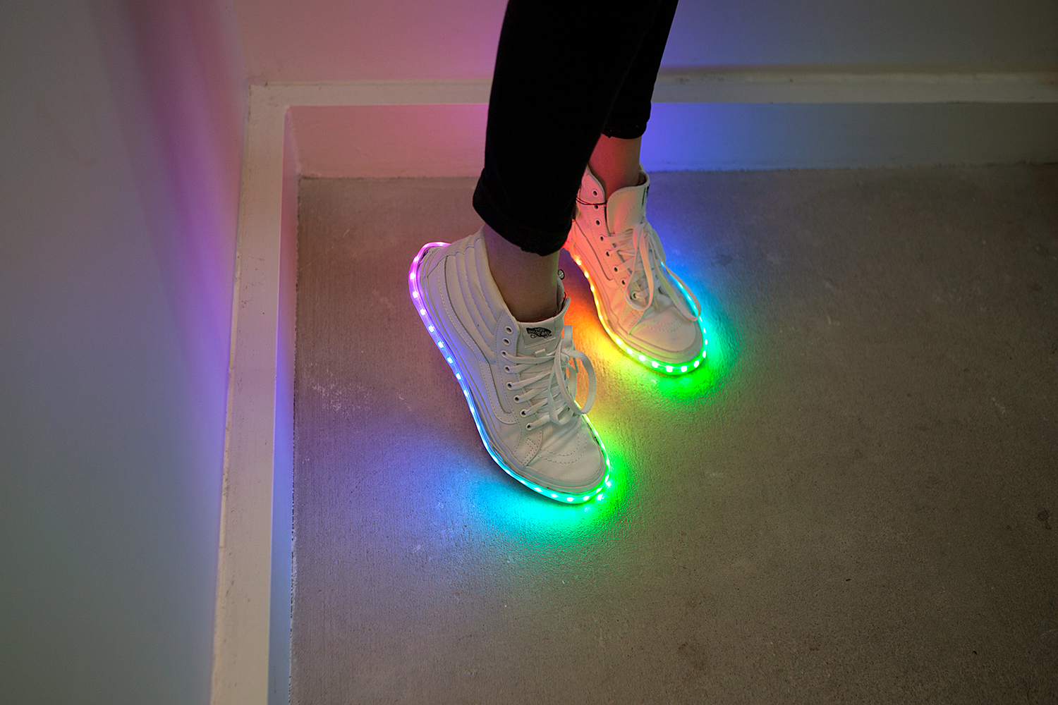
These DIY Light-Up Kicks are high top sneakers embedded with a WS2812 Addressable LED Strip and a Qduino Mini Microcontroller. The LEDs are easily programmable and re-programmable for countless customizations of color, pattern, and animation. In this tutorial we will go through the step-by-step process of building this project.
To follow along with this guide, you will need the following:
If you aren't familiar with the following concepts, we recommend checking out these tutorials before continuing.
The two main components that the Light-Up Kicks use are the following:
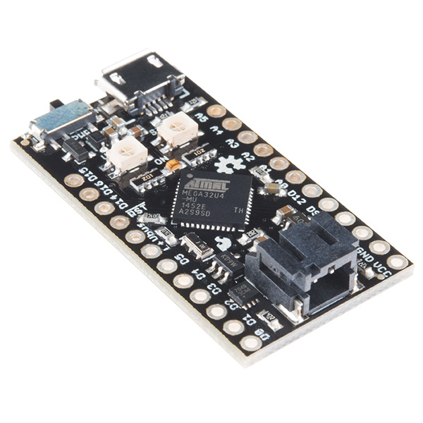
The brains behind the Light-Up Kicks are a set of Qduino Mini - Arduino Dev Boards, a small Arduino-compatible microcontroller that includes a switch AND a LiPo battery connector.
Qduino Mini Technical Specifications:
| Microcontroller | ATmega32U4 |
| Operating Voltage | 3.3V @ 8MHz |
| Digital I/O Pins | 19 with 13 dedicated |
| Analog Channels | 12 with 6 dedicated |
| Flash Memory | 32 KB |
| SRAM | 2.5 KB (ATmega32U4) |
| EEPROM | 1 KB (ATmega32U4) |
| Clock Speed | 8 MHz |
This board also features:
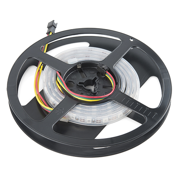
The WS2812 Addressable LED Strip is a long strip with WS2812 RGB LEDs. Each individual LED is addressable through your microcontroller. They are preterminated with 0.1" spaced 3-pin connectors as well as a 2 wire power connector. Hooking these LEDs up to a microcontroller can be done by either soldering leads to the connection pads or using the existing wire power connectors. DIN should always connect to a digital pin which will be assigned to the LED strip in your code. VCC and GND can connect to their respective pads on the Qduino Mini. A longer strip might need a more powerful or separate power source than this project requires.
The Qduino Mini - Arduino Dev Board is programmable via the Arduino IDE. If this is your first time using Arduino, please review our tutorial on installing the Arduino IDE.
If this is your first time working with the Qduino, you will need to add the board through the boards manager to your program. Please visit the Qduino hookup guide for detailed instructions on installing drivers and programming a Qduino via the Arduino IDE.
If this is your first time working with addressable LEDs, you will also need to download the Adafruit Neopixel Library. For Arduino IDE users, click on the button below to download a copy of the NeoPixel library along with some example code SparkFun has created.
If you have not previously installed an Arduino library, please check out our installation guide.
The below code is designed to animate a strip of 39 addressable LEDs. In order to test before soldering, our first step will be to program the microcontrollers.
language:c
/******************************************************************************
LED Sneakers by
Melissa Felderman @ SparkFun Electronics

This sketch directly lifts code from Adafruits Neopixel Library.
To learn more about the neopixel library and to view more sample code,
please visit here:
https://learn.adafruit.com/adafruit-neopixel-uberguide/overview
*****************************************************************************/
#include <Adafruit_NeoPixel.h>
#ifdef __AVR__
  #include <avr/power.h>
#endif

#define PIN 6

int numPix = 39 //UPDATE THIS WITH THE NUMBER OF LEDs ON YOUR STRIP

Adafruit_NeoPixel strip = Adafruit_NeoPixel(numPix, PIN, NEO_GRB + NEO_KHZ800);


void setup() {

  strip.begin();
  strip.show(); // Initialize all pixels to 'off'
}

void loop() {

  rainbow(20);
  rainbowCycle(20);
  theaterChaseRainbow(50);
}


void rainbow(uint8_t wait) {
  uint16_t i, j;

  for(j=0; j<256; j++) {
    for(i=0; i<strip.numPixels(); i++) {
      strip.setPixelColor(i, Wheel((i+j) & 255));
    }
    strip.show();
    delay(wait);
  }
}

// Slightly different, this makes the rainbow equally distributed throughout
void rainbowCycle(uint8_t wait) {
  uint16_t i, j;

  for(j=0; j<256*5; j++) { // 5 cycles of all colors on wheel
    for(i=0; i< strip.numPixels(); i++) {
      strip.setPixelColor(i, Wheel(((i * 256 / strip.numPixels()) + j) & 255));
    }
    strip.show();
    delay(wait);
  }
}


//Theatre-style crawling lights with rainbow effect
void theaterChaseRainbow(uint8_t wait) {
  for (int j=0; j < 256; j++) {     // cycle all 256 colors in the wheel
    for (int q=0; q < 3; q++) {
      for (int i=0; i < strip.numPixels(); i=i+3) {
        strip.setPixelColor(i+q, Wheel( (i+j) % 255));    //turn every third pixel on
      }
      strip.show();

      delay(wait);

      for (int i=0; i < strip.numPixels(); i=i+3) {
        strip.setPixelColor(i+q, 0);        //turn every third pixel off
      }
    }
  }
}

// Input a value 0 to 255 to get a color value.
// The colours are a transition r - g - b - back to r.
uint32_t Wheel(byte WheelPos) {
  WheelPos = 255 - WheelPos;
  if(WheelPos < 85) {
    return strip.Color(255 - WheelPos * 3, 0, WheelPos * 3);
  }
  if(WheelPos < 170) {
    WheelPos -= 85;
    return strip.Color(0, WheelPos * 3, 255 - WheelPos * 3);
  }
  WheelPos -= 170;
  return strip.Color(WheelPos * 3, 255 - WheelPos * 3, 0);
}
When you are ready, copy and paste the below program into a new window in your Arduino IDE. Update the value for int numPix to reflect the number of pixels on your strip around the shoe's sole. Make sure the correct board is selected by going to Tools > Board > Qduino Mini. Then, connect your Qduino to your computer via USB. Turn it on, and select the active port from Tools > Port. Now all you need to do is upload the program to your Qduino by hitting the upload button!
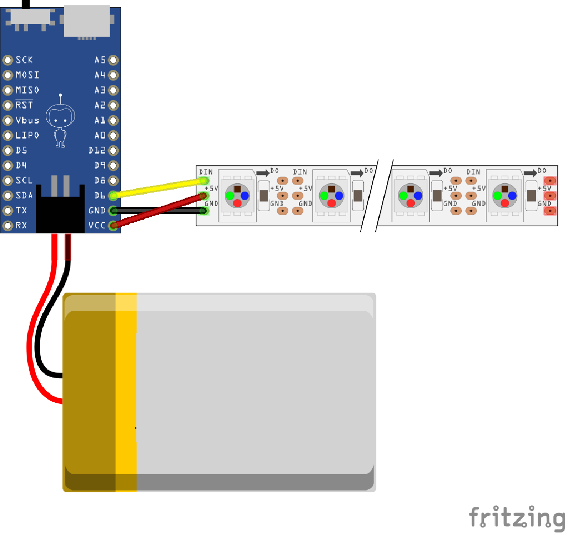
To test the program before putting it together on the shoe, try using a combination of IC hooks, alligator clips, and jumper wires to create the circuit shown below and turn on your Qduino. Make sure to connect the LiPo battery to the Qduino for sufficient power. If the LEDs animate with rainbow patterns, you are ready to move on!
Since each shoe will have a Qduino attached to control its own set of addressable LEDs, make sure to upload code to the second Qduino. Follow the steps to upload code. make sure to have the correct board and COM port selected when uploading to the second Qduino.
Now that we have tested our program with our parts, it's time to put everything together.
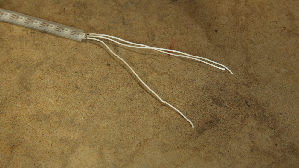
Measure the length of your shoe's sole with the LED strip. While taking note of the length, cut one LED strip to the desired shoe length between the gold pads. Cut part of the flexible silicon jacket that is used to seal the addressable LED strip so that there is room to solder to the pads.
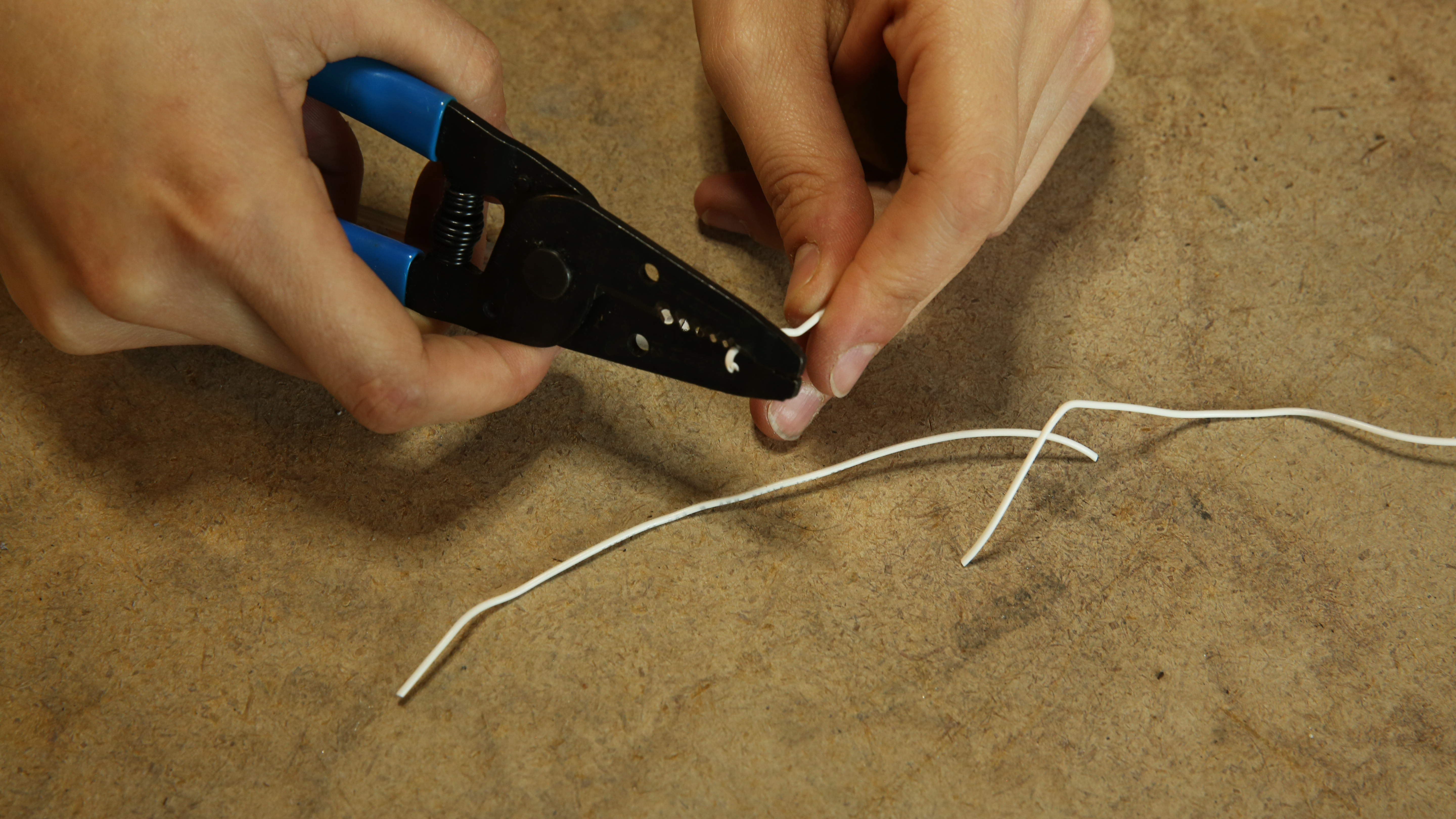
Then cut three pieces of hook-up wire, around 3-4 inches each. Strip a tiny bit at one end of each piece.
Solder each wire to each of the three pads on the LED strip.
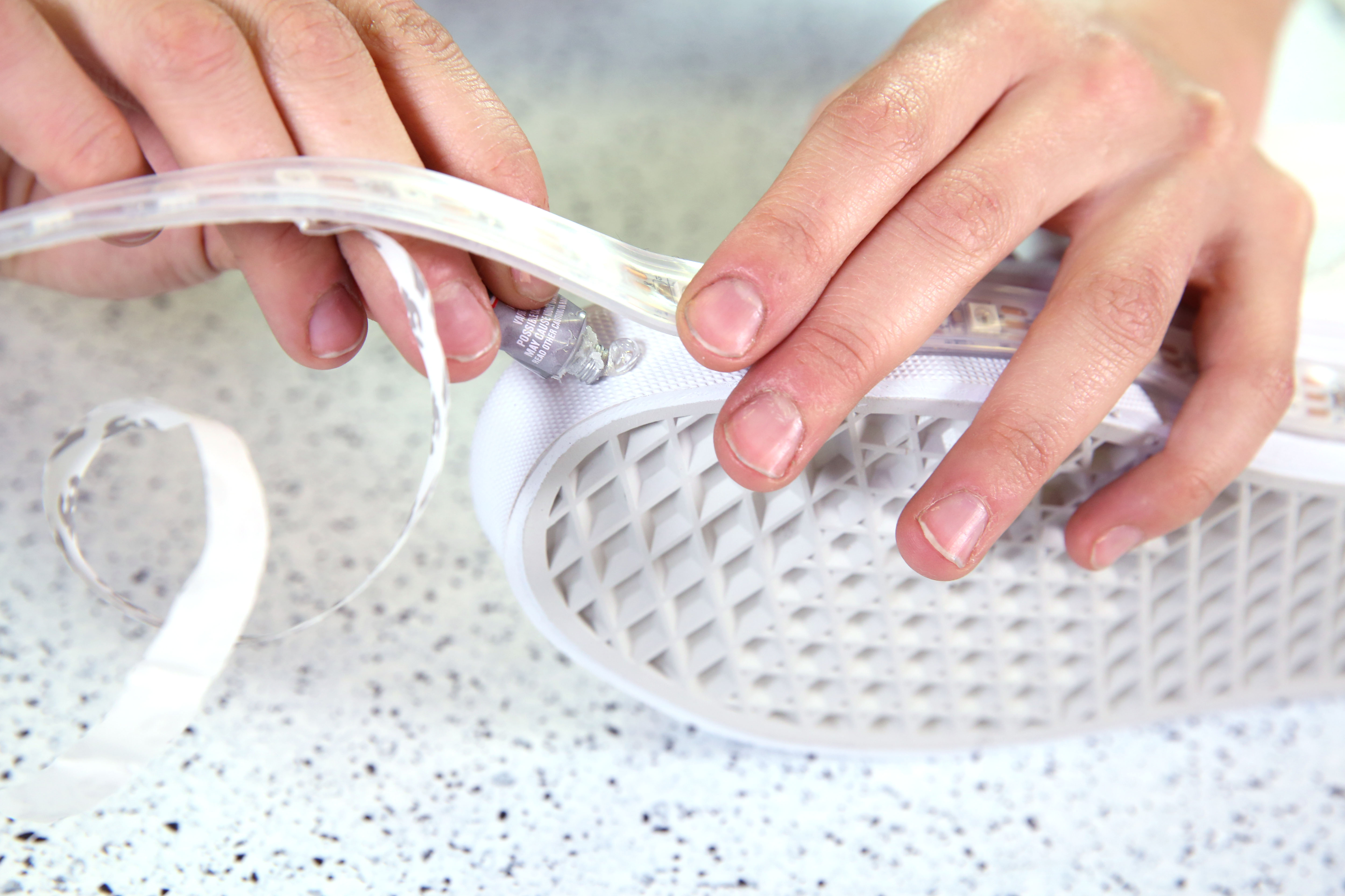
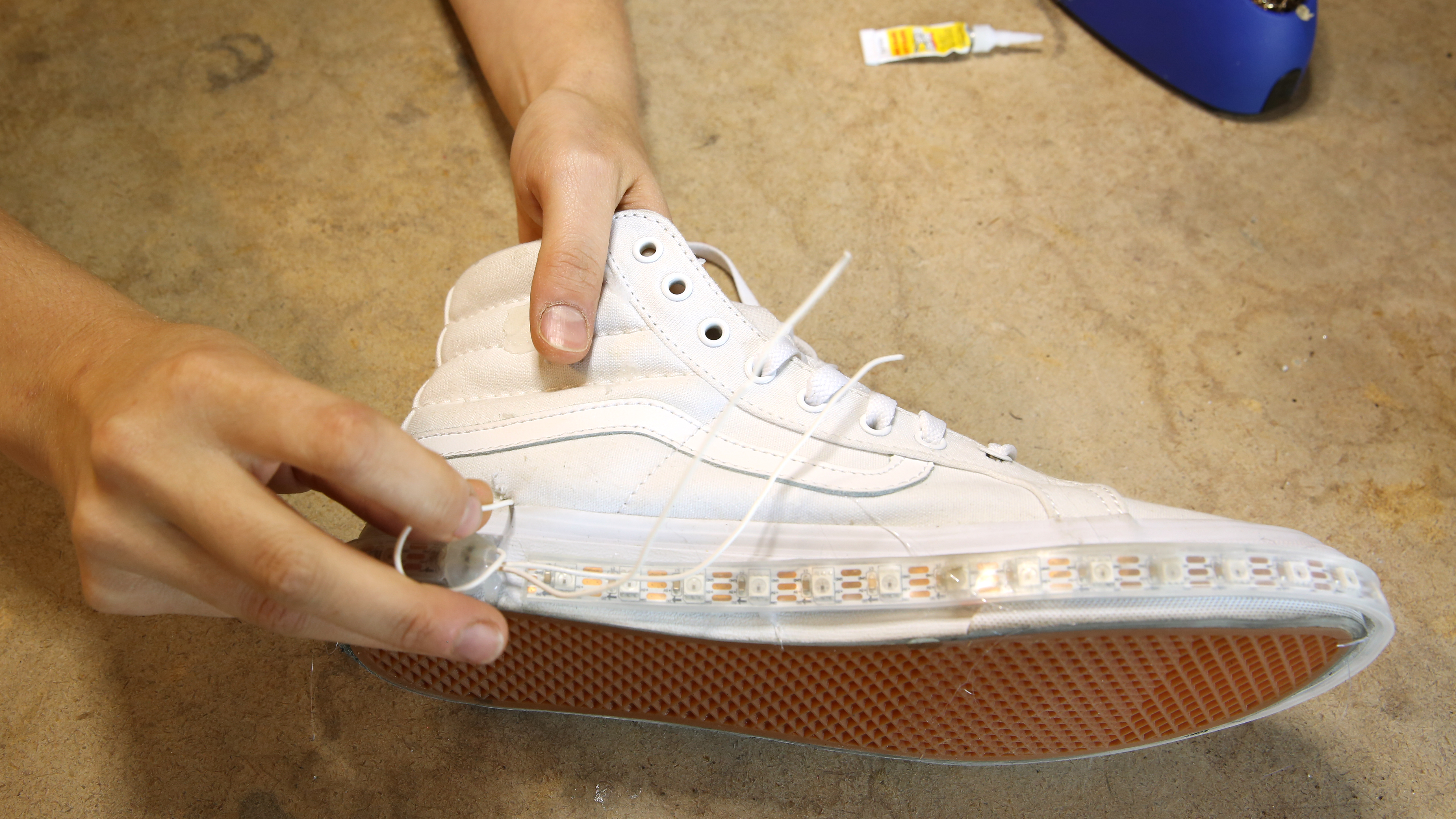
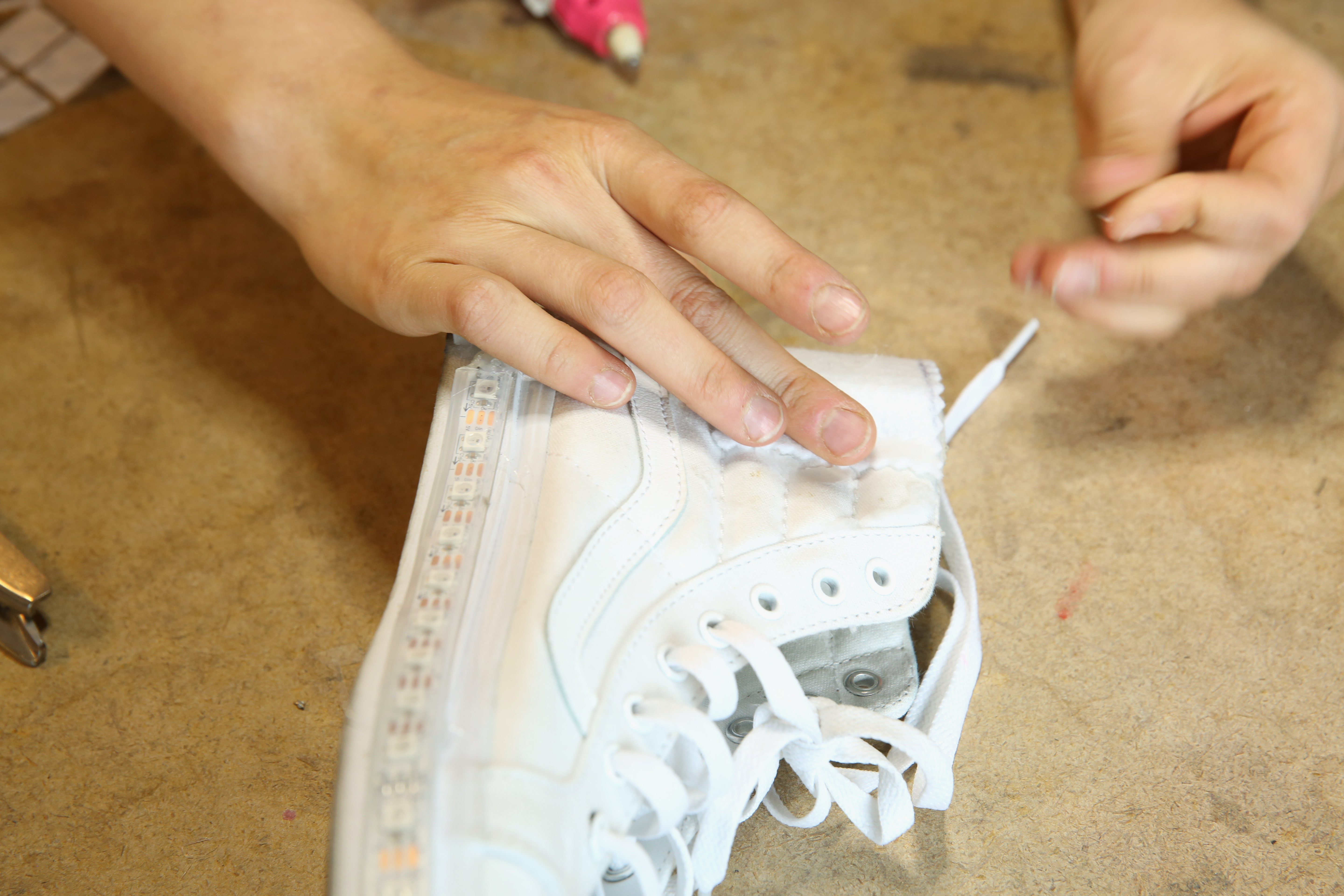
Remove the backing from the clear rubber protection around the LED strip. Starting with the soldered pads at the inner heel, begin to wrap the strip around the shoe sole. While the clear rubber does have some adhesive on the back - it is not enough to weather walking. Use super glue to make sure the LED strip is secured to the shoe sole.
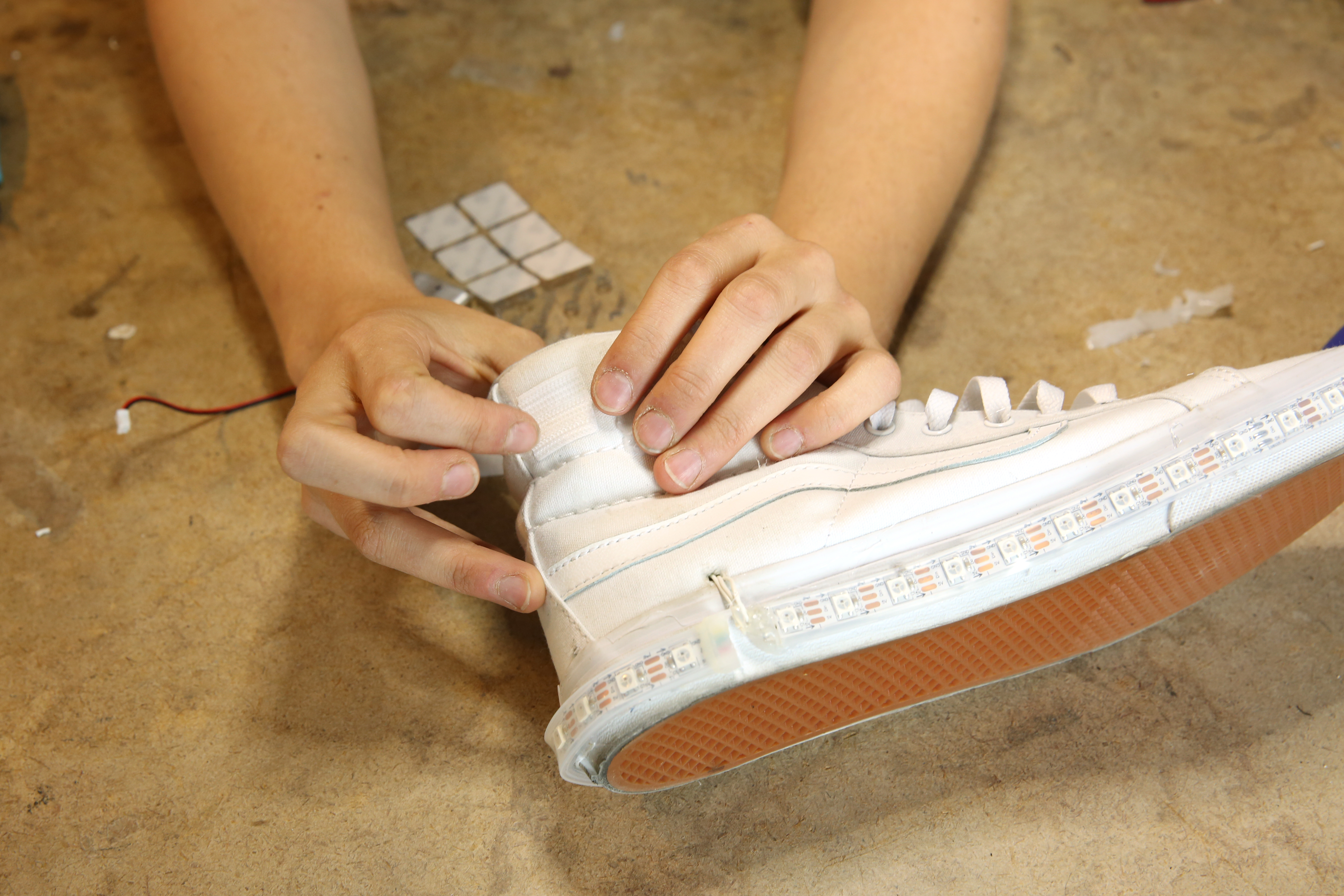
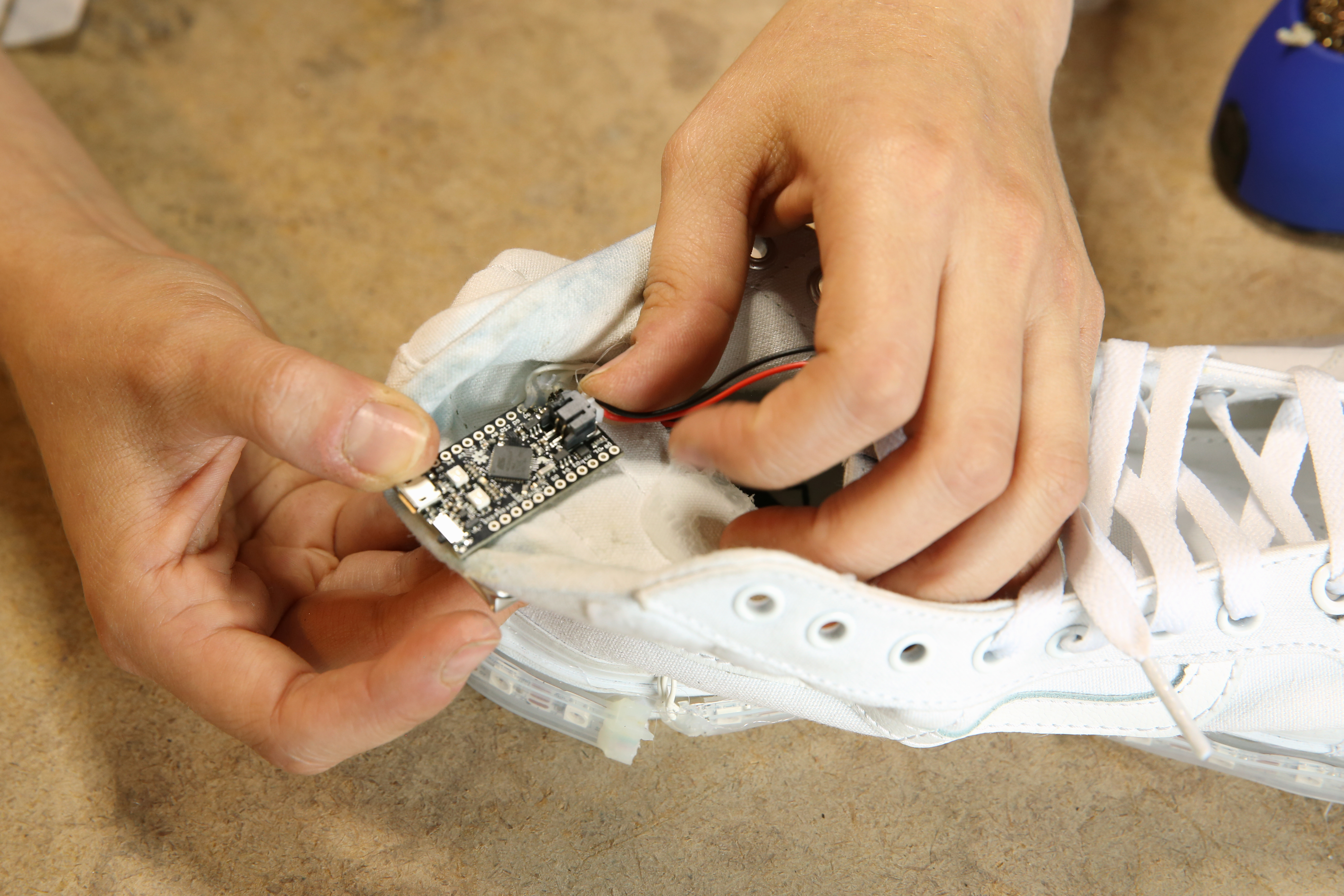
Make a small hole in the shoe directly above the end of the strip with the leads attached.
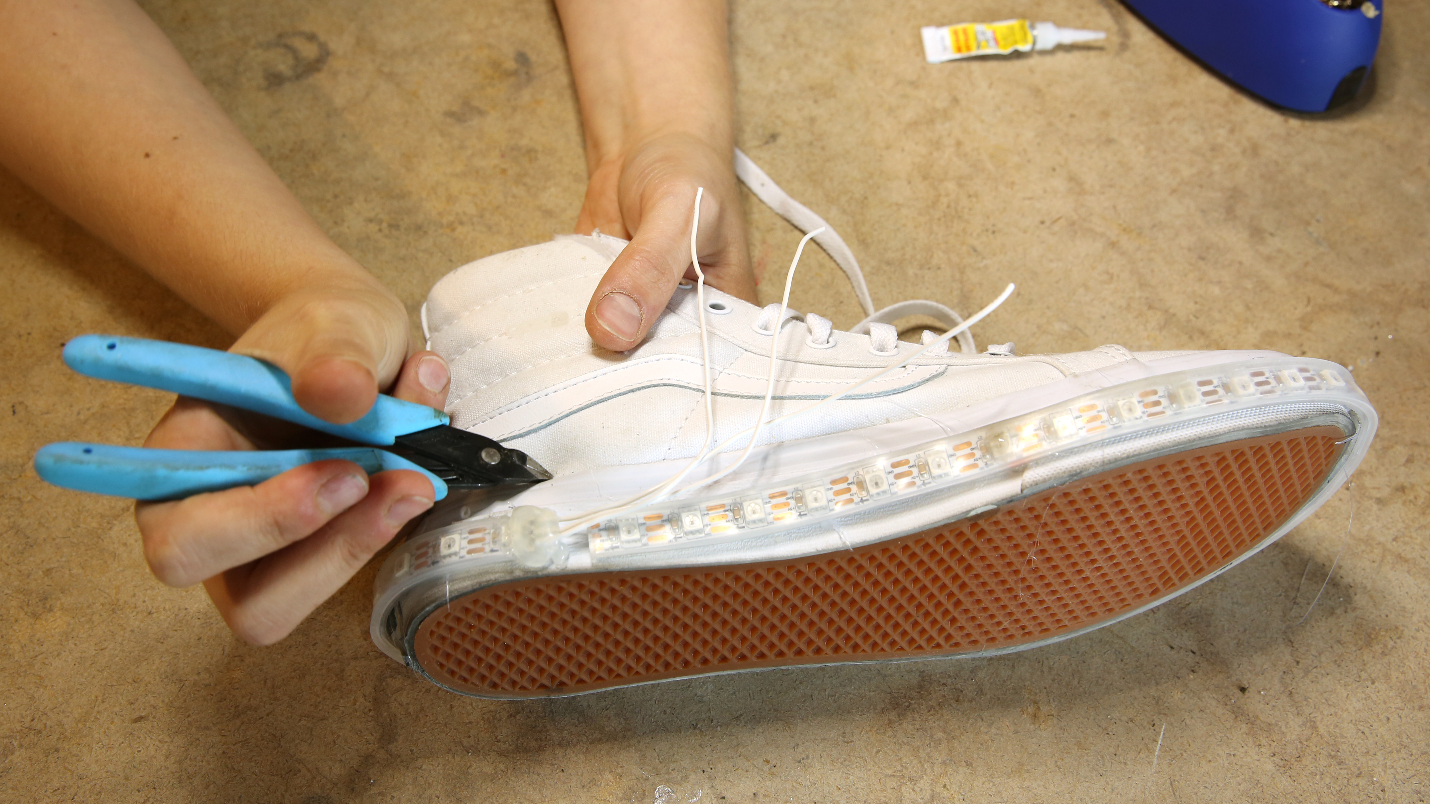
Thread the soldered leads through the hole from the outside to the inside of the shoe.
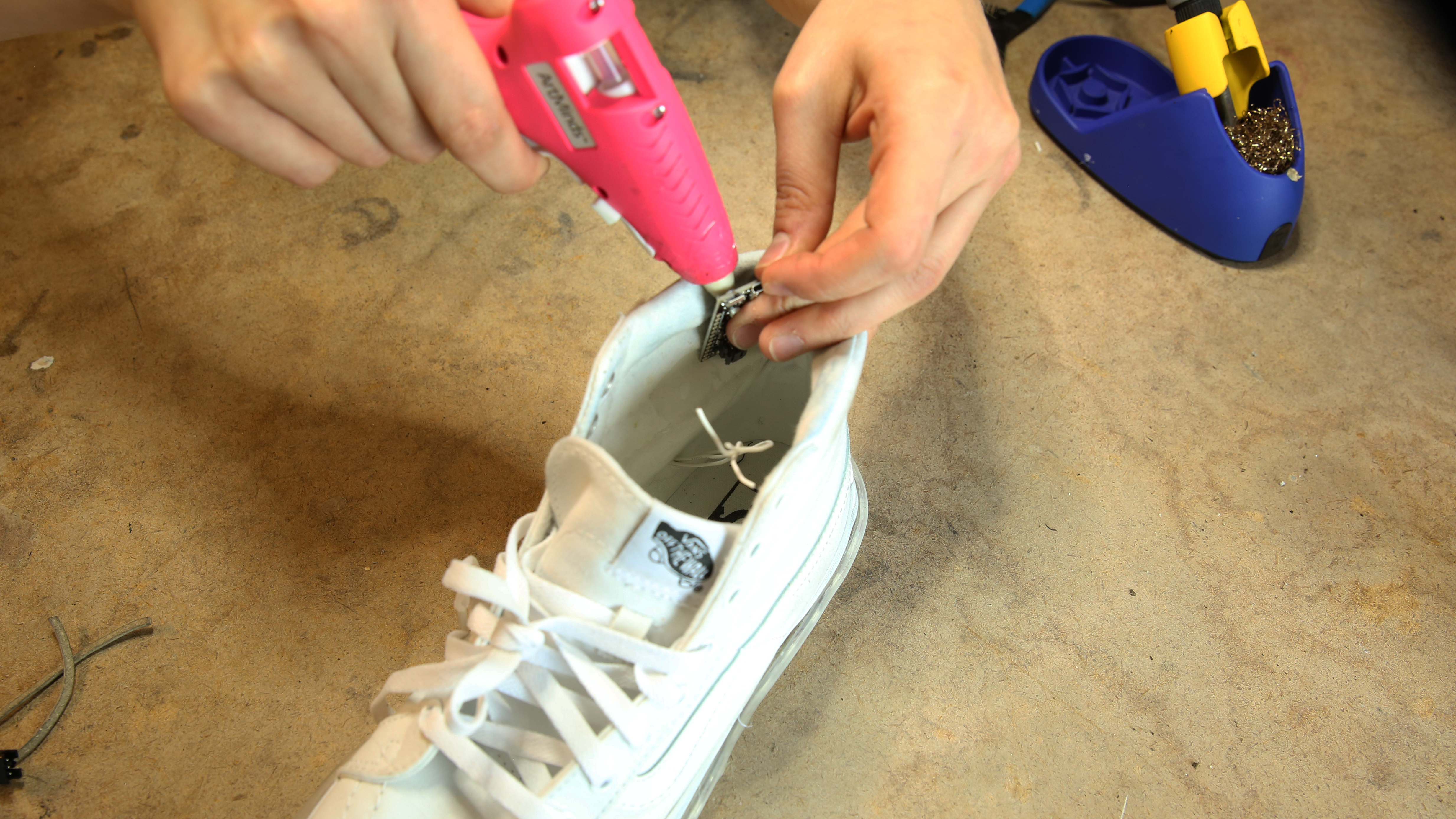
Glue the programmed Qduino to the inner ankle area, making sure to place it in a way that it will not rub against your body.
The following diagram illustrates the circuit we will be putting together visually.
Carefully solder the LED strip leads to the Qduino.
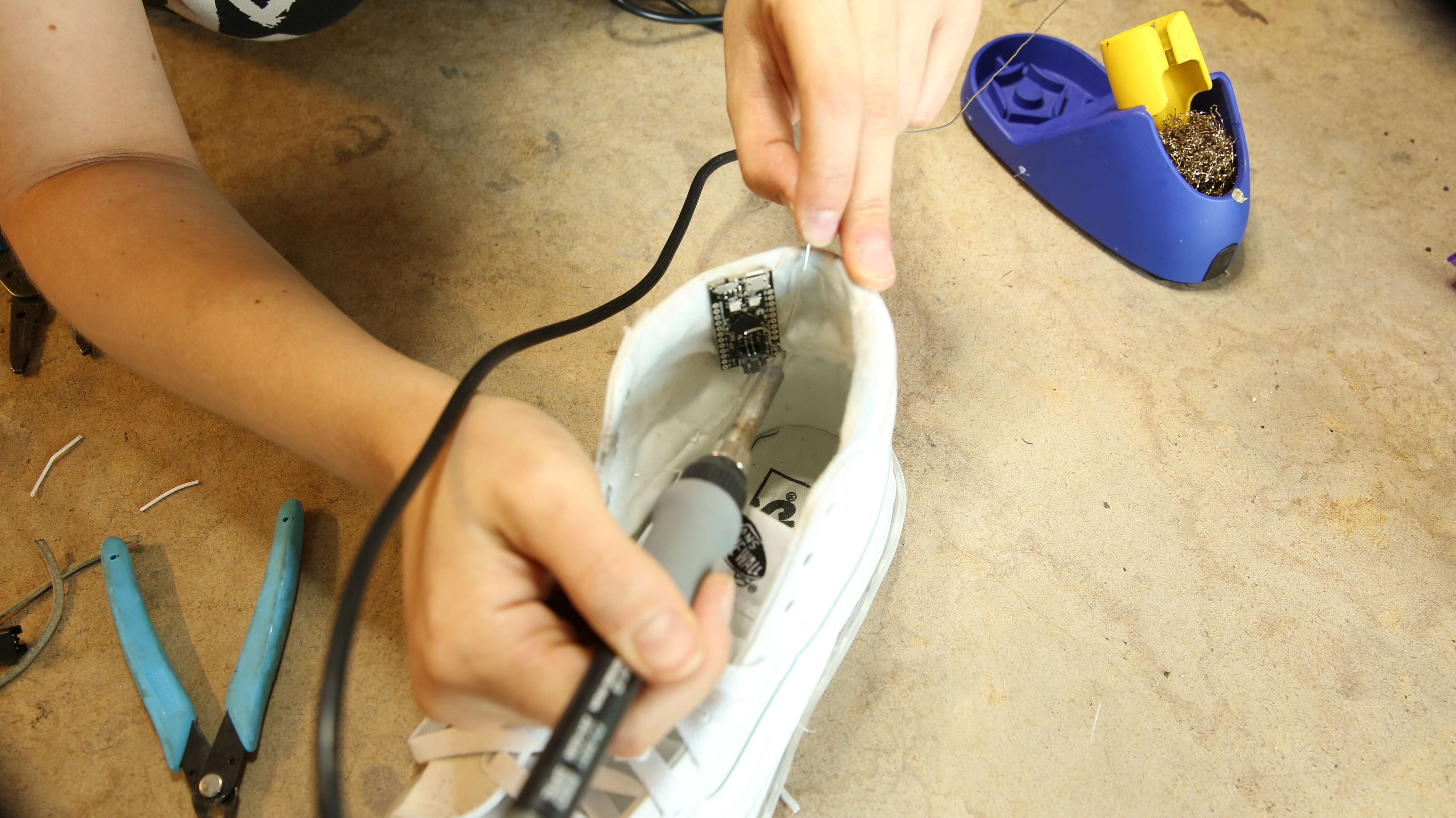
Insulate all exposed wire and solder with hot glue.
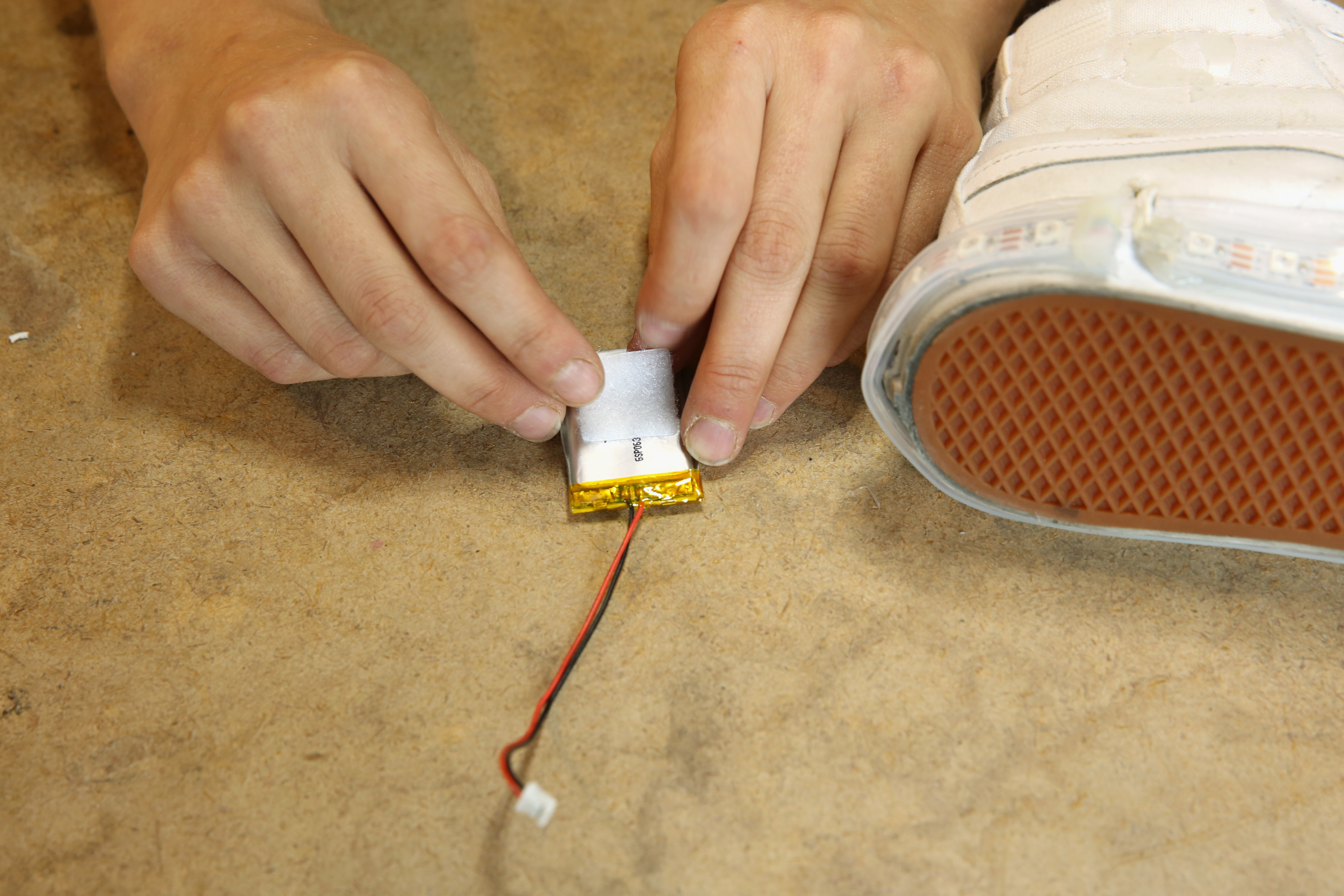
Add a small piece of Velcro to the outer side of the shoe, directly on top of the area with the Qduino glued on the other side.
Add the complimentary piece of Velcro to one side of your battery.
Poke another hole in the shoe, this time right below your Qduino.
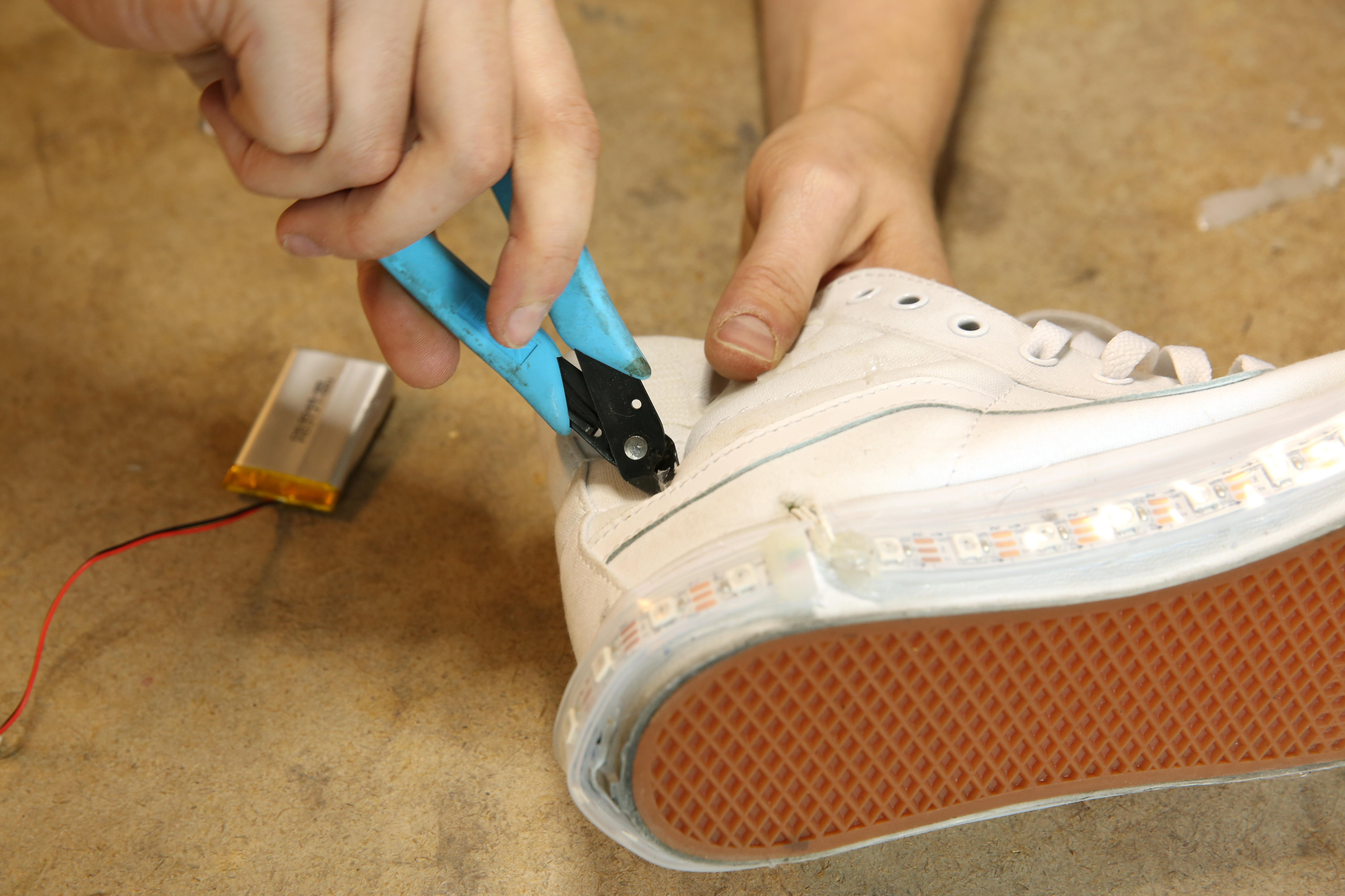
Thread the battery leads through the new hole from the outside to the inside.

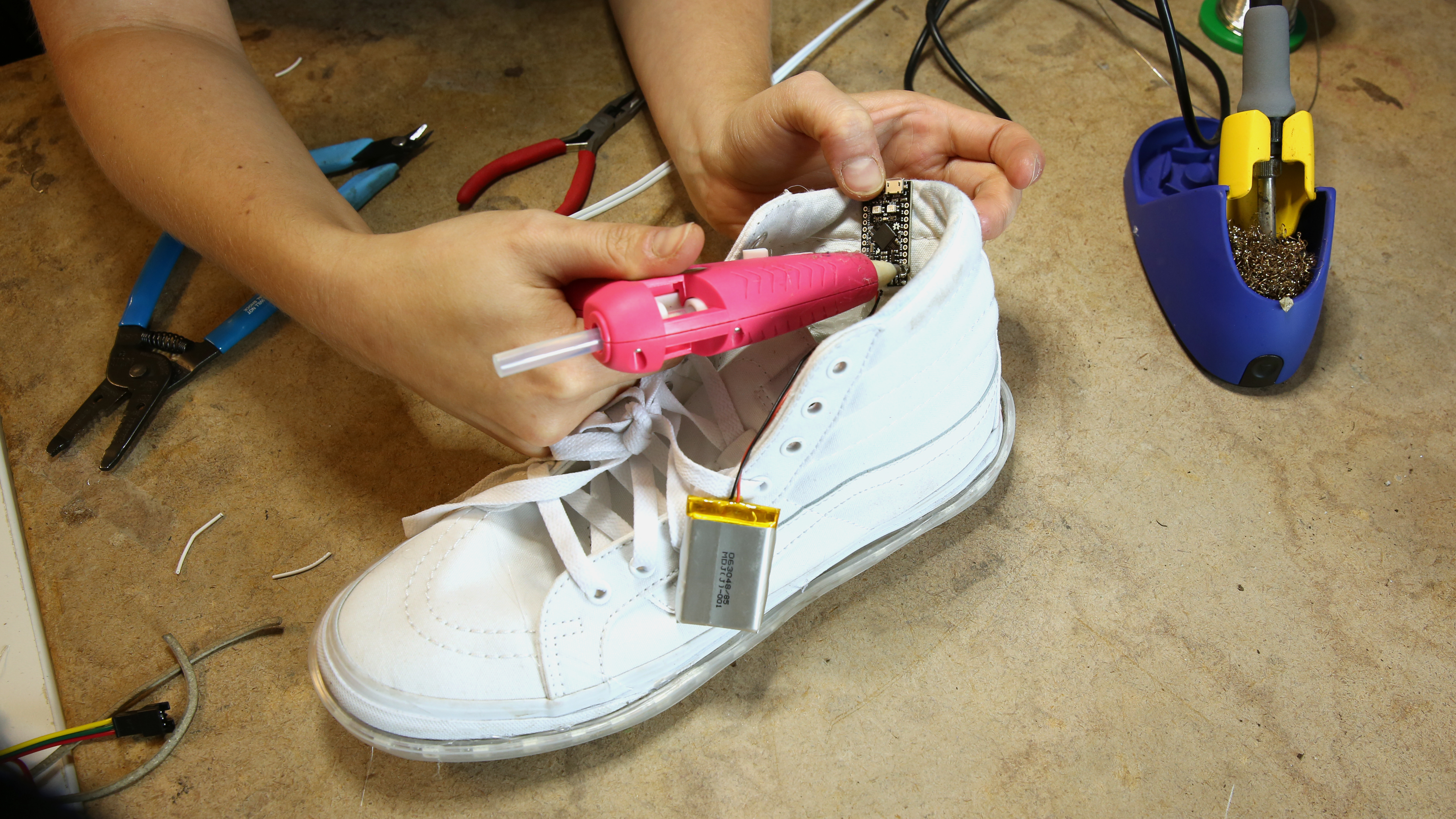
Attach the battery to the outer side of the shoe via the Velcro.
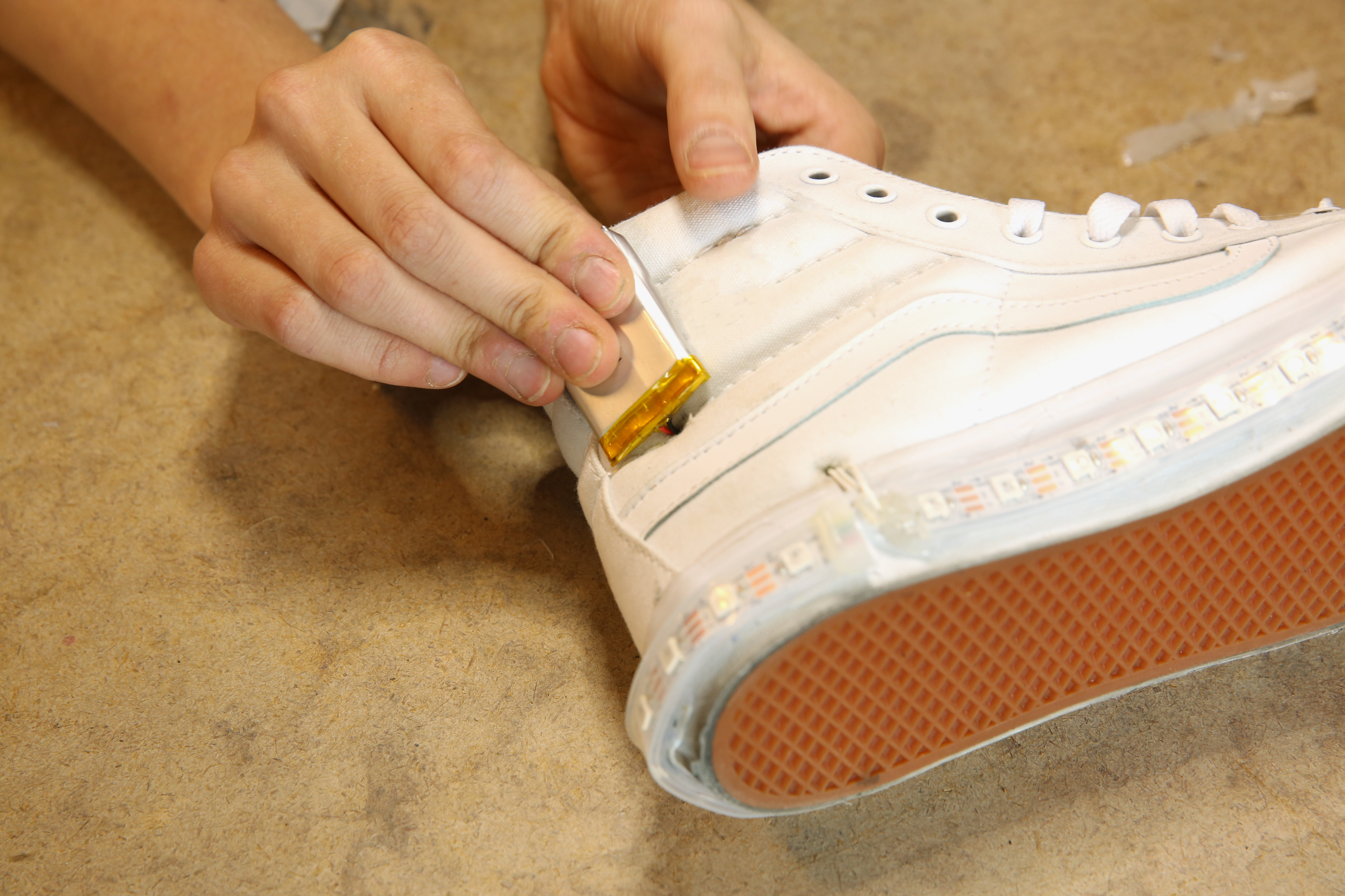
Connect the battery to the Qduino via the JST connector.
Cut out two small patches of white felt. One should be slightly larger than the Qduino and one slightly larger than the battery.
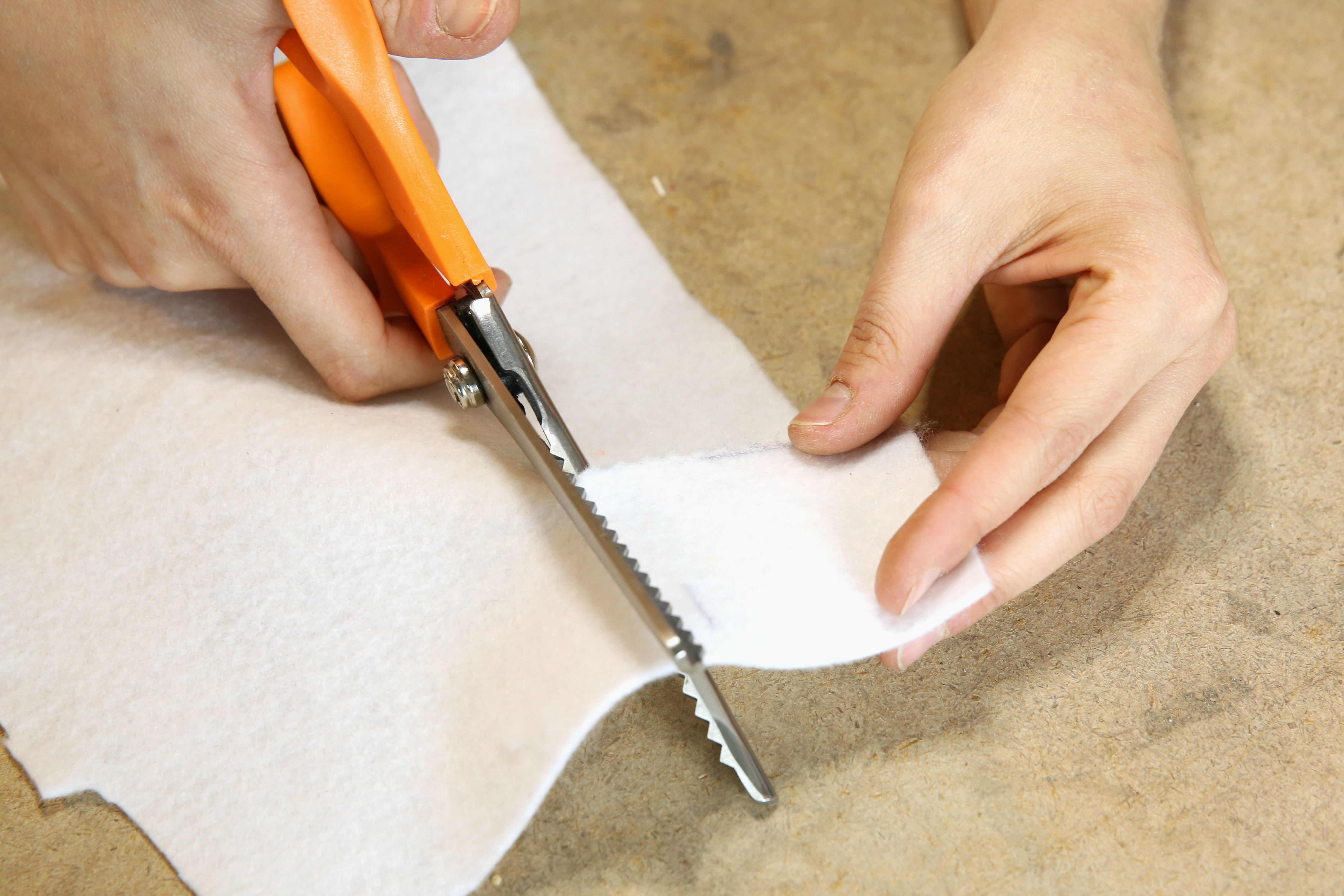
Sew or super glue the felt patched over your electronics, protecting them from the elements as well as protecting your ankles from scratching against the hardware.
Repeat steps 1-16 for the other shoe.
Use the switch on the Qduino to turn your shoes on, and enjoy!

Now that you've successfully made your own DIY Light-Up Kicks, it's time to design your own LED animation! If you'd like to learn more about the QDuino Mini or the Neopixels, you should check out these links:
Need some inspiration for your next project? Check out some of these related tutorials:
learn.sparkfun.com | CC BY-SA 3.0 | SparkFun Electronics | Niwot, Colorado