Designing with the SparkFun Artemis
Introduction
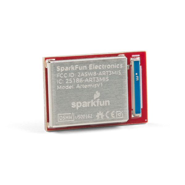
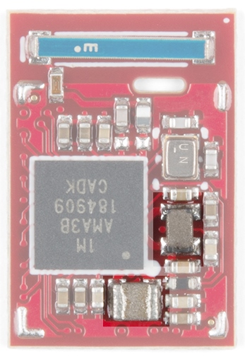
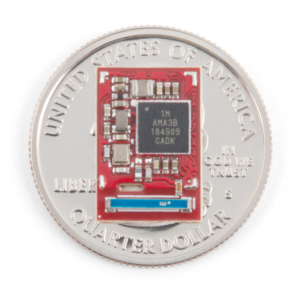
The Artemis module is the world's first open source hardware RF module enabling both voice recognition and BLE. A surprising amount of power can be packed into 10x15mm! This tutorial will walk you through the available features of the SparkFun Artemis module as well as the basics of incorporating the Artemis into your own project!
Suggested Reading
If you aren’t familiar with the following concepts, we recommend checking out these tutorials before continuing.
PCB Basics
Using EAGLE: Board Layout
Bluetooth Basics
ARM Programming
Hardware Overview
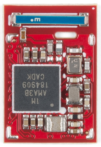
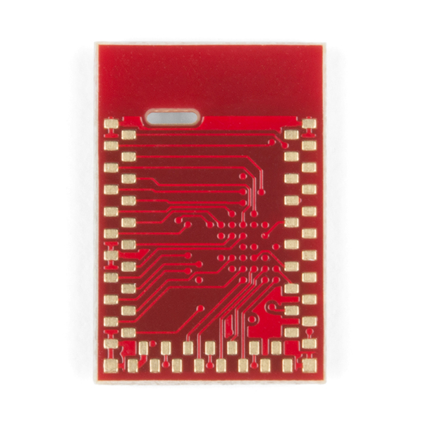
This section covers the technical details of the Artemis including the footprint and electrical characteristics. If you’ve already got a dev board with the Artemis module mounted, you can skip this section and head to Unique Features. That said, when was the last time you got to actually see inside one of these modules?
Apollo3
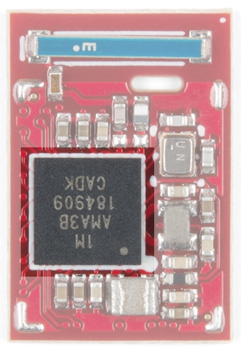
The core of the Artemis module is the Apollo3 by Ambiq. This is an ARM Cortex-M4F (F indicates hardware floating point operations) with 1M of flash and 384k of RAM. The datasheet is available here.
BLE Antenna
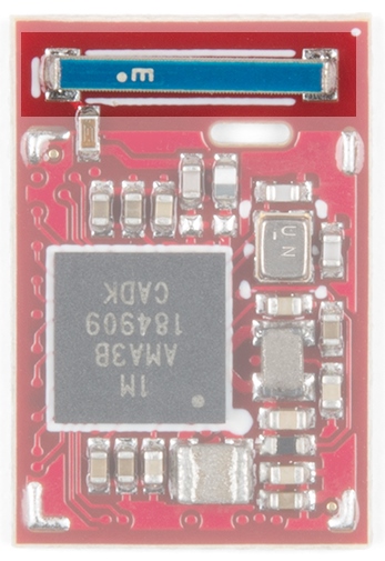
The Apollo3 has a built-in Bluetooth 5.0 radio and the module has a built in 2.4GHz antenna with 2dBi of gain.
Onboard DC Buck
The Apollo3 can operate from 3.6 to 1.8V. To allow for such a large window the Apollo3 has two built in DC buck circuits that regulate the input VCC down to the core voltage with >80% efficiency. The Artemis module includes two inductors to allow for minimum power consumption.
Dimensions
The module measures 15.5 x 10.5 x 2.3mm and weighs 0.6 grams.
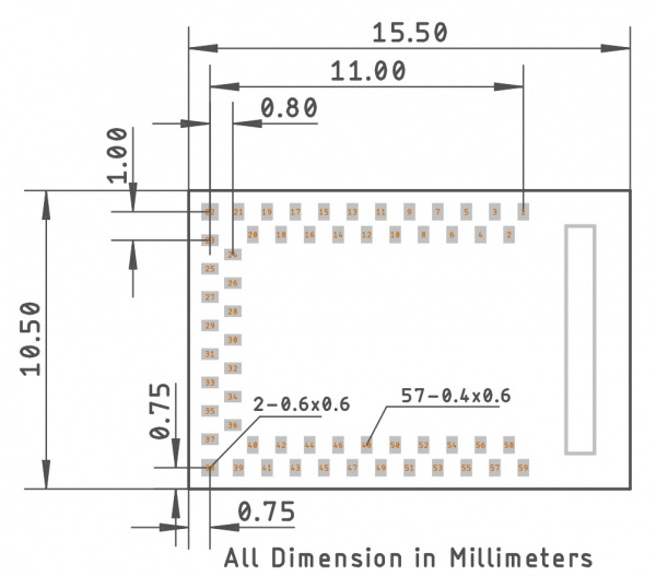
Recommended Footprint
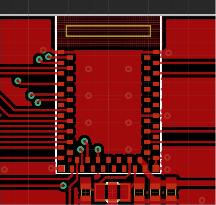
The recommended PCB layout for the module is shown here:
Be sure to checkout the Artemis Integration Guide for specific dimensions and considerations. If you design with EAGLE PCB simply clone one of our open source hardware designs that utilize the Artemis (RedBoard Artemis, RedBoard Artemis Nano, and RedBoard Artemis ATP) and begin laying out your board!
The Apollo3 is a powerful IC but its 0.5mm BGA package requires a 4 layer PCB with buried and epoxy-filled vias. This makes the PCBs expensive and difficult to produce. We designed Artemis to rid you of these concerns.
Laying out a PCB with Artemis can be done on a 2-layer PCB with 8mil trace/space. Routing under the module is allowed. Keep all ground pours away from the antenna area. If mechanical exposure allows for it the antenna can be extended over the edge of the PCB for increased reception.
Unique Features
There are a wonderful number of features packed into the Artemis. We’ll give an overview here but be sure to checkout the examples included in the Arduino core as well as the Ambiq SDK to learn more about them.
Pin Flexibility
The Artemis module has 48 interrupt capable GPIO pads and a slew of other peripherals. The 2 hardware UARTs can be re-mapped to a handful of different pads, and there are 16 fully-independent PWM outputs. An advanced high-speed 14-bit ADC is connected to 10 pads. Use either SPI or I2C masters available on 6 sets of pads.
That’s far from all -- PDM, SSC, and DMA are also available using the HAL. Checkout the pin function map, the Apollo3 datasheet, and the Ambiq SDK/HAL for more information. But don't get overwhelmed, we've got lots of examples showing how to use all the various ports and pins.
Cortex-M4F
The Artemis uses the Apollo3 from Ambiq as its core IC. This IC in turn uses the ARM Cortex-M4F running at 48MHz and an optional 96MHz burst mode. The powerful core can be programmed with GCC as well as Keil, IAR, and debugged with a variety of modern JTAG tools.
BLE
The Artemis has a built-in Bluetooth 5.0 radio capable of transmitting up to 4dBm which should get you about 70m transmission distance. We’ve seen successful RSSI checks at over 200ft.
PWM
With 31 pins out of 48 that are PWM enabled, you should be covered! Be sure to check the graphical datasheet and the pin map to see which pins have PWM capabilities.
Interrupts
Every pin can be configured as an interrupt and wake the processor from deep sleep. Additionally, all pins (except 20) have an internal pull-up that is software enabled.
14-bit ADC
Whereas the original Uno had a 10-bit converter, the Artemis has a 14-bit ADC - meaning the precision of readings goes from 0 to 1023 up to 0 to 16,383. This will enable more precise readings of sensors like analog flex, light, and sound. Note, however, that the ADC is 0V to 2V. So if you have sensor that outputs from 0 to 3.3V, it is safe, but will saturate the ADC over 2V. Use the .setResolution function to change the resolution of readings from the default of 10 to 14 or anywhere in between. Additionally, the ADC is much faster (up to 1.2 MS/s) allowing more data to be aggregated.
Low Power
Ambiq, the manufacturer of the Apollo3, has done years of research into something they call Sub-threshold Power Optimized Technology (SPOT™). This is a fancy description of a power saving technique that works by lowering the logic level voltages necessary to indicate a 1 or a 0. By doing so at the silicon level, Ambiq has managed to eke out a 48MHz processor running at less than half a milliamp. "Always on" monitoring of voice commands, without the need for BLE or a connection to the internet, takes approximately 6μA/MHz.
Burst mode
Sometimes 48MHz is not enough. The processor has the ability to enter a 96MHz burst mode where internal calculations and monitoring can be accomplished in half the time.
JTAG
Modern power calls for modern debugging tools. The Artemis is based on a Cortex-M4F which has a JTAG port dedicated to debugging. With a JTAG debugger you can set break points, inspect registers and see what assembly and C instructions are being executed. It’s a tool that you’ll not often need, but when you need it, it’s a life saver.
PDM
One of the shining uses of the Artemis is for 'always on' voice recognition. Digital MEMS microphones are more sensitive and easier to use than their analog parents. The Artemis has a built-in PDM port allowing for up to 2 MEMS microphones to be used as either dual channel or in beam-forming applications.
Internal Pull Ups
Every pin has an internal weak pull-up that is software enabled. Additionally, the pins configured as I2C ports have software selectable pull-ups (1.5k, 6k, 12k, 24kΩ) eliminating the need for external SDA and SCL pull-ups.
Pin Drive Strength
One of the more unique features of the Artemis is its ability to have selectable drive strength on all GPIO. 2, 4, 8, or 12mA can be selected as the max current on a given pin. Additionally pads 3 and 36 have selectable high side power switch transistors to provide ~1 Ω switches to VDDH. Pads 37 and 41 have a selectable low side power switch transistors to provide ~1Ω switches to VSS.
Security
The Cortex-M4F inside Artemis contains multiple layers of security including Secure Boot, OTA, Keystorage, as well as inline encryption/decryption of external flash (like an SD card).
Programming
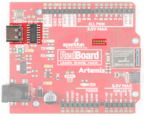
Artemis can be programmed using the standard JTAG interface or with a serial bootloader. You'll find a USB connector for serial bootloading with the CH340 or a JTAG footprint for more advanced programming and debugging, on a variety of dev boards from SparkFun. For more information on ARM programming, including JTAG interfaces, check out our ARM Programming Tutorial.
SparkFun Bootloader
We've designed a baud rate flexible bootloader that is run at each power on reset. What does baud rate flexible mean exactly? The computer and bootloader initiate communication at 9600bps, then agree to go to a faster baud rate to transfer the bulk of the binary data. This enables upload speeds up to 921600bps; significantly reducing upload times. A flexible rate allows computer systems that may have problems at higher rates to select the rate that works best. This bootloader is the preferred method for uploading sketches and user code that needs quick and reliable means of getting new code onto the Artemis.
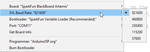
Once you've selected an Artemis target board additional menu options will appear the next time you open the Tools menu. The SVL Baud Rate options will allow you to change the upload speed. 921600bps is the recommended speed as it's extremely fast to update new sketches. However, there are some platforms (Linux flavors) where the standard CH340 USB to serial drivers don't operate well at speeds higher than 115200. So if you run into upload problems, consider reducing the upload speed. For more information about upload issues, see this forum post and consider upgrading with these drivers for Mac OSX or these for Linux.
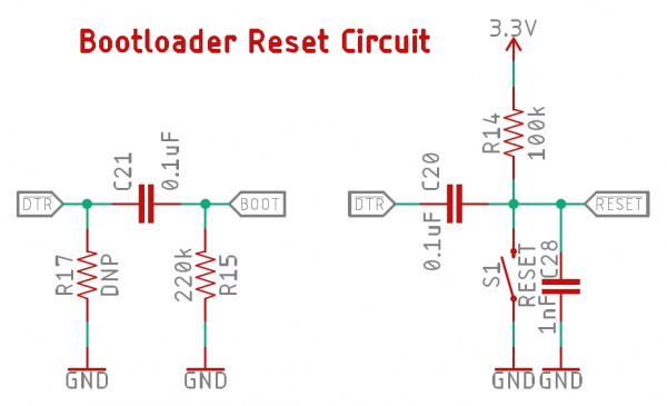
Just like the classic Arduino Uno, Arduino Mega, etc, the bootloader is activated by resetting the board. A single 0.1uF capacitor between DTR and reset is all that is needed to cause the Artemis to reset and enter bootload mode. If no new firmware is detected within a short amount of time (50ms), user code is run.
If you're into niche electrical engineering discussions on things like bootloaders, you can read more about the Artemis bootloader here.
Factory Bootloader
In addition to the SparkFun Artemis bootloader, we program every Artemis with the Ambiq factory Secure Bootloader (SBL). This bootloader is best used for low-level updates of devices that need to have a secure provenance. The bootloader is activated at reset if pin 47 is high and communicates at 115200. The bootloader will then wait indefinitely for new binary data. We provide a python tool as well as an executable to communicate with this bootloader.
This style of bootloading is slightly different from bootloaders that you may be accustomed to. The STK500 bootloader that runs on most ATmega328 based Arduinos is run automatically at reset, then times out and the user’s code is run. The Artemis bootloader is similar but requires an extra pin (the Bootload pin) to be held high. To make using Artemis as cheap and easy as possible we’ve designed a simple RC circuit that can be implemented on your design using USB-to-serial ICs with the bare minimum control pins (the CH340E has only RTS) and still allow for factory bootloader activation. If you suspect you will need to modify the SparkFun Artemis Bootloader (described above) or if you need to use the secure bootload toolchain, the circuit above can be used to bootload using a single pin (DTR or RTS is supported). This single-pin reset and bootload solution is ideal for any USB to serial implementation that has control pins exposed (CH340, CP210x, FT232, etc).
To load new code onto your Artemis module using the Ambiq bootloader toolchain select the Ambiq Secure Bootloader option in the Arduino Tools->Bootloader menu. These tools will modify your binary and package them with various security headers. The code will load at 115200bps and may fail. Hit upload again if the process fails.
How the Single Pin RC Circuit Works
By pulling DTR (or RTS) low, the module is reset. After 10ms, DTR is pushed high in software. This causes the bootload pin to be high for 100ms allowing the bootloader to run. Opening of a serial port causes DTR to go low causing the module to reset, but because DTR stays low during normal serial operations the module does not enter the SBL and instead proceeds to run the SparkFun Artemis Bootloader.
We have modified the Ambiq python bootload tool so that both DTR and RTS are driven at the same time, and in the same way, so you can use either RTS or DTR to bootload the Artemis. Our Ambiq SBL tools then drive DTR/RTS high to enter the the factory bootloader.
If you prefer, the bootload pin can be broken out to a button. When the user holds the button and resets the board the Artemis will enter bootload mode and stay there until a bootload cycle completes or a reset occurs. This method works well but requires the user’s interaction every time new code needs to be loaded.
Troubleshooting
If your product is not working as you expected or you need technical assistance or information, head on over to the SparkFun Technical Assistance page for some initial troubleshooting.
If you don't find what you need there, the SparkFun Forums are a great place to find and ask for help. If this is your first visit, you'll need to create a Forum Account to search product forums and post questions.
SparkFun Artemis Forums
I accidentally used the Ambiq bootloader. Now the SparkFun Variable Loader doesn't work. What do I do?
You just couldn't help yourself and you loaded code with the Ambiq bootloader. That's ok! To get your module re-loaded with SparkFun SVL bootloader follow these steps:
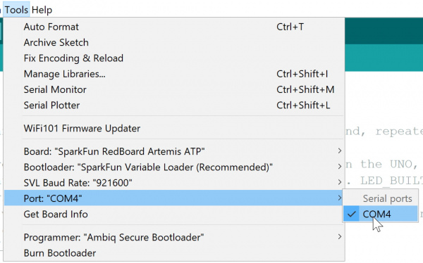
Step 1: Select the right board and COM port in Arduino.
Double check that you have the correct board and COM port selected on the Tools menu. COM 4 is shown in the above image but your COM port may be different.
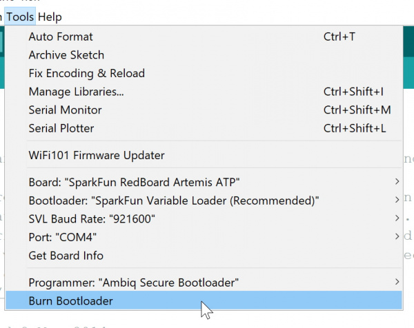
Step 2: Select Burn Bootloader from Tools menu
This will cause Arduino to use the Ambiq factory bootloader to re-load the SparkFun Variable Loader over serial.
Step 3: Change your Bootload Tool to SVL
Let's not do that again, ok? Change the Bootloader back to SVL. Now all your sketches will upload much faster.
Resources and Going Further
Here's a list of quick links to the resources provided in this tutorial:
- Artemis Integration Guide
- Apollo3 DataSheet (PDF)
- Pin Function Map
- Ambiq SDK/HAL
- JTAG Tools
- Artemis Bootloader GitHub
- SparkFun Arduino Apollo3 GitHub
- ARM Programming Tutorial
- Ambiq
Ready to use Artemis inside Arduino? Checkout the Artemis Development with Arduino tutorial.
Are you more comfortable with a make file and an IDE? Checkout the tutorial on how to setup the Ambiq Apollo3 SDK.
And lastly, Artemis has been designed and proven to work with our entire range of 50+ Qwiic boards. Be sure to check out and get inspired by what's possible by just plugging in the sensors and outputs you need to build something amazing!
Check out some of these Artemis/Apollo3 related boards and tutorials:
Installing Board Definitions in the Arduino IDE
SparkFun expLoRaBLE Hookup Guide
Qwiic ToF Imager - VL53L5CX Hookup Guide
Getting Started with Machinechat
Or check out these blog posts.
