Designing with MicroMod
 Nate
Nate 
How to Design a MicroMod Carrier Board
Start with a known good carrier board; the MicroMod Machine Learning Carrier Board is a good example.
The core of the carrier board is the MicroMod M.2 connector, standoff and screw.

We carefully designed the standoff to be reflowable and compatible with the 4.2mm high M.2 connector so that carrier boards can have a limited number of components underneath the Processor Board. Additionally, the screw was chosen to be slightly larger (M2.5) with a Phillips head so that users will have the best experience possible. We recommend checking that you have a #00, #0, or #1 Phillips head driver available. If not, our classic SparkFun reversible mini-screw driver or the fancier pocket screw driver set work great.
For those folks that don't use EAGLE the datasheets including footprints follow:
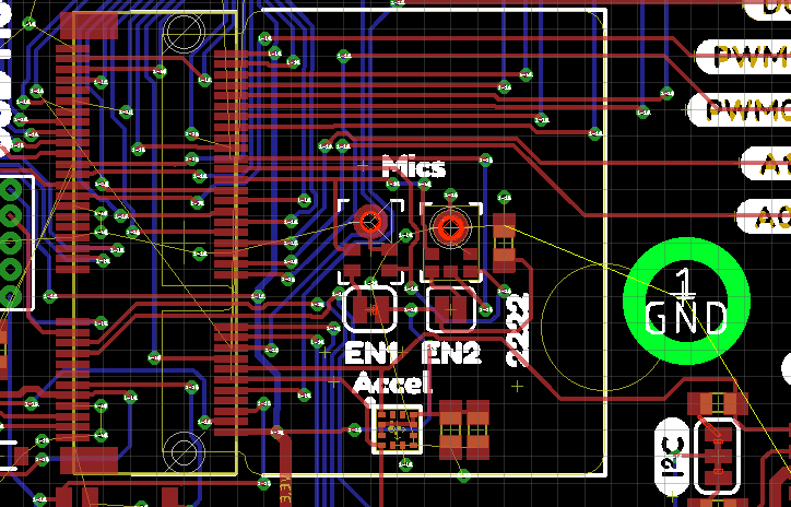
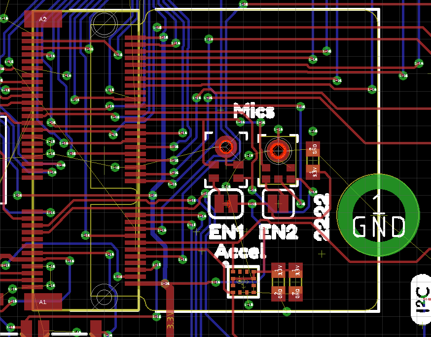
Open up the SparkFun Eagle library and navigate to the 'SparkFun-MicroMod' library. The SMD reflowable standoff is a separate component (found in the 'SparkFun-Hardware' library) from the MicroMod connector so that we can track the parts correctly in Sparkle (the SparkFun's in house ERP system). The connector has a circle where the standoff needs to fall. It needs to be close but not micron perfect. We currently plan to only have 22x22mm MicroMods Processor Boards (note the ‘2222’ text) but this may grow in the future.
We currently recommend using the AP7361C 3.3V 1A linear regulator. In addition, please include the zener and pullup on the enable pin. This allows a MicroMod Processor Board to turn off the main power supply when necessary, enabling considerable power savings. The zener protects the MicroMod Processor Board from damage to its GPIO from VIN.
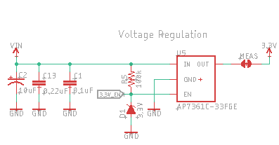
Note the MEAS jumper below. This allows for cutting and inline current measuring. Note the BYP jumper. This allows the user to bypass the PTC and increase current use beyond 2A PTC cut off if supported by their power supply.

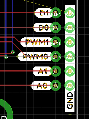
Interface pins should be grouped together but their location on the board is not specified.
 |
 |
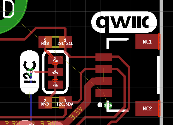
A Qwiic connector with pullups and a logo should be put on every carrier board. Note the thick 0.022” 3.3V trace enabling 2A delivered to the Qwiic bus.
Components under the MicroMod Processor Board are allowed. Be careful of component height! Any component placed under MicroMod with 4.2mm height connector (the standard connector we stock) must be less than 1.9mm +/-0.1mm tall. No Artemis (too tall), yes SOT-23-5, yes CH340C/E. Double check the height of the components on the bottom of all MicroMod Processor Boards.
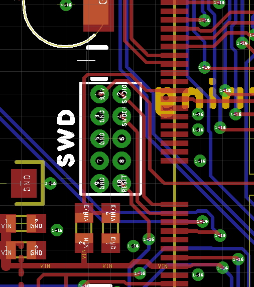
All carrier boards should have a Serial Wire Debug (SWD) port. Not all processor support SWD but many do.
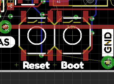
Add a reset button and consider adding a boot button. Currently, the boot input is not utilized on many Processor Boards but should be included for future use. We prefer the SMD button with the 5.2mm actuator (feels great!).
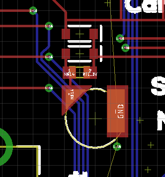
Consider adding RTC/low power backup to your board. The RTC backup battery configuration shown is pretty well tested. It’s compact, SMD compatible, and provides 1mAh of capacity. Your application may be high power (a motor driver) where RTC doesn’t make sense. It’s ok to leave off.
Now add anything you may need to your carrier board for your specific application. LiPo charging, DB9, RFID, whatever. The power of MicroMod and the challenge to you is to consider how your added peripherals are going to play with the various MicroMod Processor Boards. Adding a serial device is straightforward, most all Processor Boards will have TX/RX1. Adding a PDM microphone or 4 bit high speed (Quad SPI) display takes more consideration.
Routing is straightforward. Match the length of any high speed traces such as USB D+/D-, USB HOST D+/D-. Consider using 7mil trace/space with 0.012” drills. Ues 0.022” traces for up to 2A power buses. Smaller traces down to 0.0035mil and 0.2mm drills are allowed but highly unlikely we’ll need it. Four layer boards are cheap these days but again, highly unlikely we’ll need it. Carrier boards should be much less complex because all the complexity should be pushed into the Processor Board.
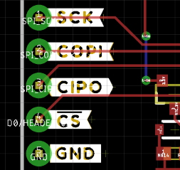
Pull-ups on Chip Select (CS) pins: Pull-ups live with the peripheral. So if the carrier board has a SPI device on the board (SD, sensor, etc), that device needs to have a pull up on the CS pin. If the CS line is simply brought out to a PTH header on the edge of a board it does not need a pull-up (that pull-up should live on the peripheral that gets soldered to the SPI pins). Use a 100k where possible but the value can be changed as the peripheral’s datasheet specifies.