Designing with MicroMod
 Nate
Nate 
How to Design a Function Board
What's in a Function Board?
A Function Board is a modular PCB made to plug into an M.2 connector. Similar in theory to the Processor board (plug and play), but targeted at peripherals for the processor board. The function boards are made to interconnect with Processor Boards on a larger main board. This creates an ecosystem in which no soldering iron is required for multiple embedded systems to interact smoothly and efficiently.
Physical Dimensions and Layout
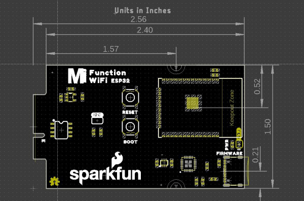
The Function Board comes in a single size that is 65mm X 38mm (2.56" x 1.5"). The PCB inserts into a M.2 connector and as a result is 0.8mm thick, half the thickness of a standard PCB.
 |
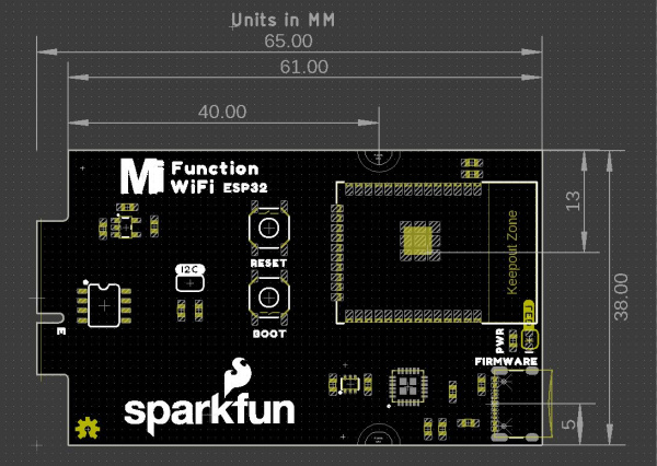 |
| Dimensions in Inches | Dimensions in Millimeters |
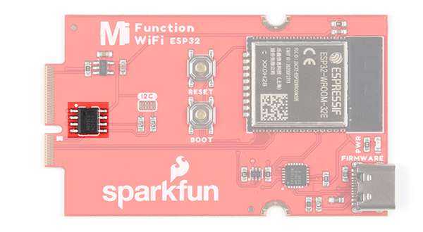
The edge opposite the card edge always includes any connectors needed by the Function Board. For example, the WiFi Function Board includes a USB-C connector for uploading AT Command Firmware to the ESP32; the LoRa board includes an SMA connector for an antenna.
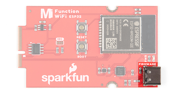
This helps with ease of use, but also for placing a Function with in a case. Speaking of ease of use, connectors should sit at some measurement within the Function board's PCB that doesn't require five decimal points of precision.
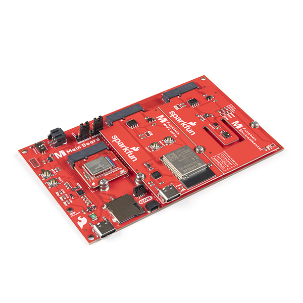
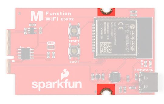
There are and must be at least two standoffs for securing the Function Board down to keep the board from moving when plugging in cables on the card edge.
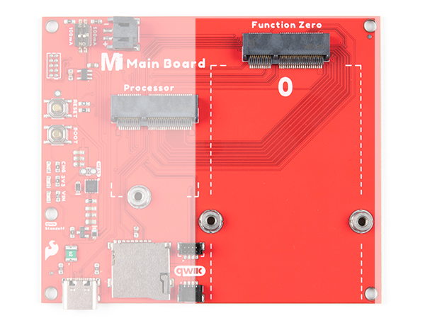
You can see the complementary female standoffs on the Main Board - Single that secure the Function Board to the PCB.
M.2 Card Pinout
The M.2 pinout includes many of the major buses: Serial Peripheral Interface (SPI), Inter-Integrated Circuit (I2C), Serial, USB Host, and the Control Area Network (CAN) Bus. There are eight digital pins with a number of dedicated overlapped functionalities at the lower enumerated pin numbers. For example F0 is a dedicated interrupt, F1 includes a dedicated Chip Select pin for the SPI bus, and F2 is a dedicated Pulse Width Modulation (PWM) pin. Aside from the general purpose pins, there is a single analog pin A0 and finally, a power enable pin. The power enable pin's intended use is to allow power to the function board to be easily switched on and off. On SparkFun's Function boards we simply use popcorn voltage regulators to facilitate power, passing the power enable pin to the card's edge, making it easy to shut off power.
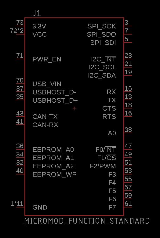
The MicroMod Function Board symbol and footprint can be found within the SparkFun Eagle Libraries Repository within the SparkFun-Micromod.lib. The device name is MicroMod-Function which includes the Function Board under the "MICROMOD-FUNCTION-STANDARD" variant, and the M.2 connector under the "MICROMOD-FUNCTION-MAIN" variant.
The Parts
This might go without saying, but the Function Board should have all the included parts necessary to support any ICs on it. For example, if the intention is for the Function Boards to be a datalogger, consider putting an SD Card socket on it.
Additionally we've included an EEPROM on each of the Function Boards and it contains basic information about the Function Board.
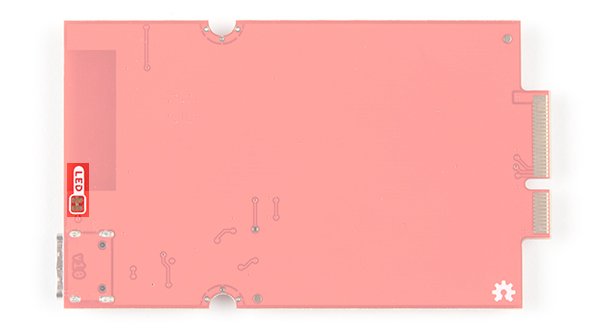
The MicroMod ecosystem always wants to support low power applications as much as possible. If your Function Board has any LEDs than include jumpers to remove power from them.