Calibrating Your Odometry Sensor
Introduction
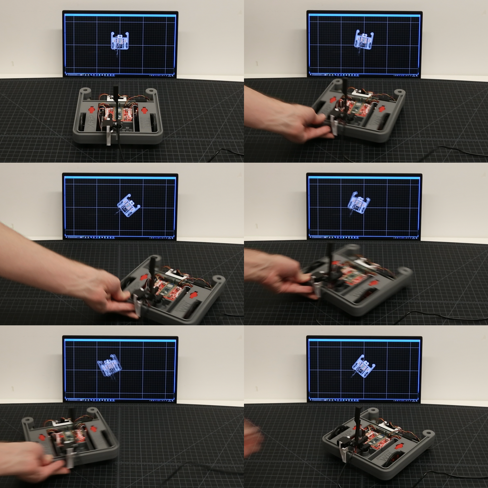
The SparkFun Qwiic Optical Tracking Odometry Sensor empowers you to elevate your robot's navigation capabilities with exceptional precision and streamlined integration. This compact, all-in-one sensor leverages the power of the PAA5160E1 chip from PixArt Imaging Inc., delivering accurate dual-axis motion data across various hard floor surfaces. But that's not all! This sensor boasts a powerful built-in 6-axis Inertial Measurement Unit (IMU) and an onboard microcontroller that performs real-time sensor fusion and tracking algorithms.
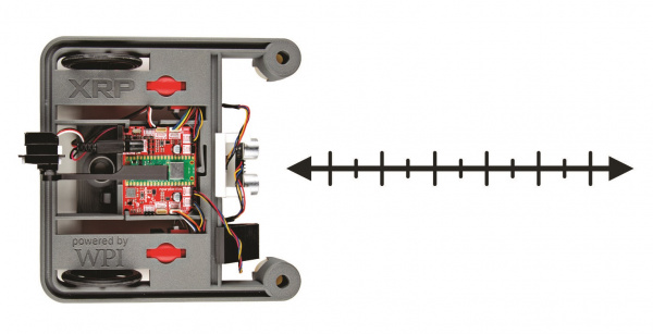
In this tutorial, we will be going over how to calibrate your Qwiic Optical Tracking Odometry Sensor (or "OTOS") with Arduino and Python Examples. While we recommend using the OTOS with our XRP robotics platform (specifically for FTC teams), following this guide, you will be able to use the Odometry Sensor with any robot you feel comfortable with!
If you are looking for the full Hookup Guide for the SparkFun Qwiic Optical Tracking Odometry Sensor, click the button bellow. This guide only covers sensor calibration to get you started, while the full Hookup Guide goes over every detail of the sensor.
Hardware Needed
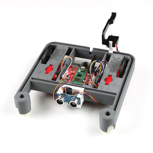
To follow along with this tutorial, you may need the following materials. You may not need everything though depending on what you have and what robotics platform you are using. Again, while we recommend the XRP Kit, the choice is ultimately yours. Add it to your cart, read through the guide, and adjust the cart as necessary.
Software Setup
Arduino
We've written a library to get you started with the SparkFun Optical Tracking Odometry Sensor. You can obtain this library through the Arduino Library Manager by searching for "SparkFun Qwiic OTOS Arduino Library" and installing the latest version from SparkFun. If you prefer downloading libraries manually, you can grab them from the GitHub Repository.
Python
In addition to the library provided above, we have written a Python script that allows you to visualize an XRP in real time. Download via the button below.
Linux/Raspberry Pi Variants
We've written a python package to get you started with the SparkFun Optical Tracking Odometry Sensor. It's been included in the SparkFun Qwiic Python package, which aggregates all Python Qwiic drivers/modules to provide a single entity for Qwiic within a Python environment. The Qwiic_Py GitHub Library ReadMe has more information on the Qwiic Python package.
If you already have your Qwiic Python package installed, you can update it with the following command:
pip install --upgrade sparkfun-qwiic
If you don't have the Qwiic Python package installed already, you can install it with the following command:
pip install sparkfun-qwiic
If you prefer to install just this package, use the following command:
pip install sparkfun-qwiic-otos
If you prefer downloading the code to build and install the package manually, you can grab them from the GitHub Repository.
If you are working with a Raspberry Pi and are using the new Bookworm distribution of the Raspberry Pi OS, refer to these instructions to setup a virtual environment.
Make sure to include the --system-site-packages flag:python3 -m venv --system-site-packages
Then it is possible to install the packages using pip.
XRP/MicroControllers
If you are working with the XRP or other microcontroller, pip will not work for you. Instead, you'll need to install the Qwiic_I2C_Py driver as well as the Qwiic_OTOS driver.
Install Qwiic_OTOS_Py
Qwiic_I2C_Py is a generic I2C driver we have created to work on various platforms (such as MicroPython). Our Qwiic Python device drivers take advantage of Qwiic_I2C_Py to function correctly on any of the supported platforms, so it is a required dependency to use our OTOS Python driver.
Fist, go to the Qwiic_I2C_Py repository and download it as a .zip file. Once downloaded, extract the qwiic_i2c folder within.
Connect your XRP to your computer over USB, navigate to the XRPCode IDE, and connect to your XRP. For usage information, see the XRPCode User Guide.
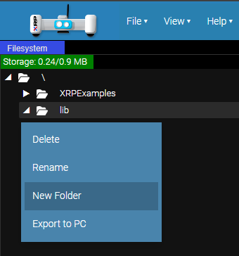
Create a new folder within the lib directory (right-click on the folder), and name it qwiic_i2c.
lib directory qwiic_i2c Upload the files from the previously extracted qwiic_i2c folder into the new folder you just created on the XRP. From the File menu, choose the Upload to XRP option:
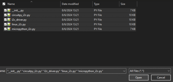
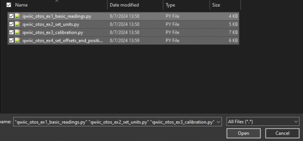
Then select the extracted files:
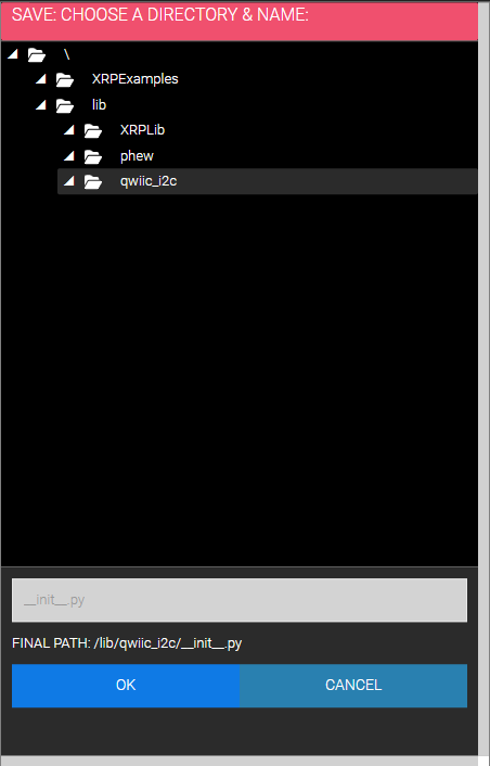
Then choose the newly created qwiic_i2c folder on the XRP:
qwiic_i2c folder Uploading...
You can test to confirm correct installation by typing import qwiic_i2c followed by qwiic_i2c.get_i2c_driver().scan() in the Shell. If no errors are printed, then the Qwiic_I2C_Py driver has been installed correctly!
Install Qwiic_OTOS_Py
Fist, go to the Qwiic_OTOS_Py repository and download just the qwiic_otos.py file.
Connect your XRP to your computer over USB, navigate to the XRPCode editor, and connect to your XRP. For usage information, see the XRPCode User Guide.
Upload the qwiic_otos.py file into the lib folder on the XRP. From the File menu, choose the Upload to XRP option:
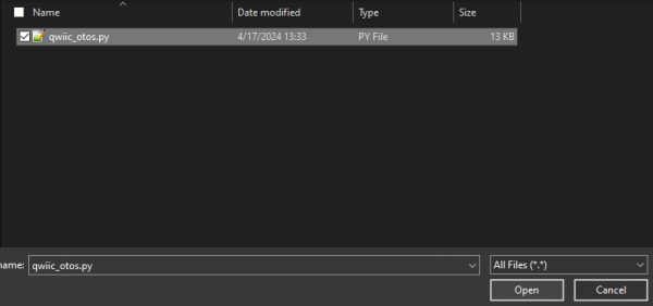
Select the qwiic_otos.py file:
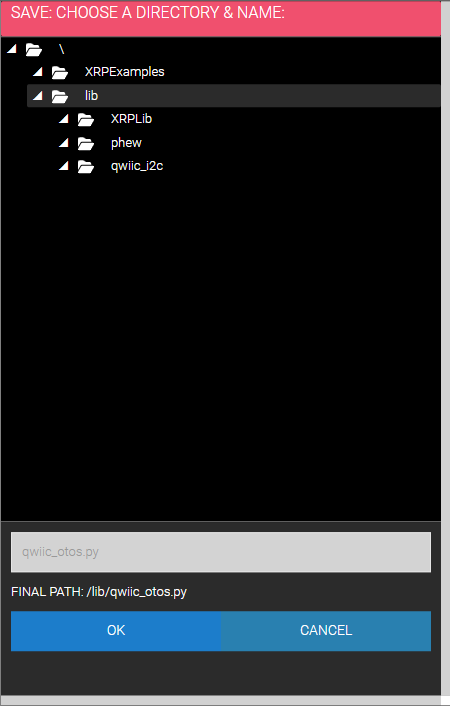
Then select the lib folder on the XRP:
lib folder on the XRP Updating...
You can test to confirm correct installation by typing import qwiic_otos followed by qwiic_otos.QwiicOTOS().is_connected() in the Shell. If no errors are printed, then the Qwiic_OTOS_Py driver has been installed correctly!
Testing the install:
Visualization
In addition to the package provided here, we have written a Python script that allows you to visualize the XRP in real time. Download via the button below.
Arduino Examples & Calibration
Example 1: Basic Readings
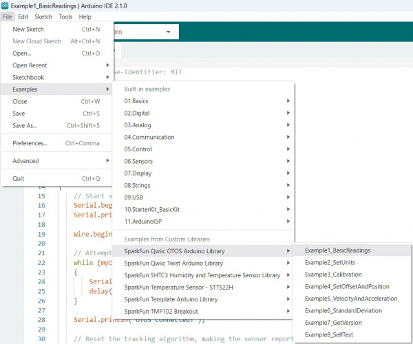
This first example just does some basic measurements to make sure everything is hooked up correctly. To find Example 1, go to File > Examples > SparkFun Qwiic OTOS > Example1_BasicReadings:
Alternatively, you can expand the link below and copy and paste the code into a shiny new Arduino sketch:
/*
    SPDX-License-Identifier: MIT

    Copyright (c) 2024 SparkFun Electronics
*/

/*******************************************************************************
    Example 1 - Basic Readings

    This example demonstrates how to read the position and heading from the
    SparkFun Qwiic Optical Tracking Odometry Sensor (OTOS).

    This example should be used to verify that the OTOS is connected and
    functioning correctly. It will just print the position and heading tracked
    by the OTOS to the serial monitor. It is recommended that you check out the
    other examples before using the OTOS in your own project.
*******************************************************************************/

#include "SparkFun_Qwiic_OTOS_Arduino_Library.h"
#include "Wire.h"

// Create an Optical Tracking Odometry Sensor object
QwiicOTOS myOtos;

void setup()
{
    // Start serial
    Serial.begin(115200);
    Serial.println("Qwiic OTOS Example 1 - Basic Readings");

    Wire.begin();

    // Attempt to begin the sensor
    while (myOtos.begin() == false)
    {
        Serial.println("OTOS not connected, check your wiring and I2C address!");
        delay(1000);
    }

    Serial.println("OTOS connected!");

    Serial.println("Ensure the OTOS is flat and stationary, then enter any key to calibrate the IMU");

    // Clear the serial buffer
    while (Serial.available())
        Serial.read();
    // Wait for user input
    while (!Serial.available())
        ;

    Serial.println("Calibrating IMU...");

    // Calibrate the IMU, which removes the accelerometer and gyroscope offsets
    myOtos.calibrateImu();

    // Reset the tracking algorithm - this resets the position to the origin,
    // but can also be used to recover from some rare tracking errors
    myOtos.resetTracking();
}

void loop()
{
    // Get the latest position, which includes the x and y coordinates, plus the
    // heading angle
    sfe_otos_pose2d_t myPosition;
    myOtos.getPosition(myPosition);

    // Print measurement
    Serial.println();
    Serial.println("Position:");
    Serial.print("X (Inches): ");
    Serial.println(myPosition.x);
    Serial.print("Y (Inches): ");
    Serial.println(myPosition.y);
    Serial.print("Heading (Degrees): ");
    Serial.println(myPosition.h);

    // Wait a bit so we don't spam the serial port
    delay(500);

    // Alternatively, you can comment out the print and delay code above, and
    // instead use the following code to rapidly refresh the data
    // Serial.print(myPosition.x);
    // Serial.print("\t");
    // Serial.print(myPosition.y);
    // Serial.print("\t");
    // Serial.println(myPosition.h);
    // delay(10);
}
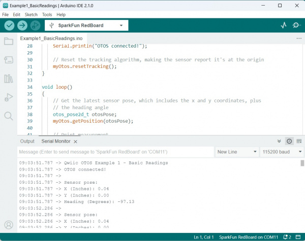
Make sure you've selected the correct board and port in the Tools menu and then hit the upload button. Once the code has finished uploading, go ahead and open a Serial Monitor. You should see something similar to the following.
Example 2: SetUnits
This example sets the desired units for linear and angular measurements. Can be either meters or inches for linear, and radians or degrees for angular. If not set, the default is inches and degrees. Note that this setting is not stored in the sensor, it's part of the library, so you need to set at the start of all your programs.
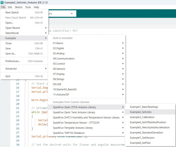
To find Example 2, go to File > Examples > SparkFun Qwiic OTOS > Example2_SetUnits:
Alternatively, you can expand the link below and copy and paste the code into a shiny new Arduino sketch:
/*
    SPDX-License-Identifier: MIT

    Copyright (c) 2024 SparkFun Electronics
*/

/*******************************************************************************
    Example 2 - Set Units

    This example demonstrates how to change the units of the SparkFun Qwiic
    Optical Tracking Odometry Sensor (OTOS).

    The OTOS library defaults to inches and degrees, but you can change the
    units to suit the needs of your project.
*******************************************************************************/

#include "SparkFun_Qwiic_OTOS_Arduino_Library.h"
#include "Wire.h"

// Create an Optical Tracking Odometry Sensor object
QwiicOTOS myOtos;

void setup()
{
    // Start serial
    Serial.begin(115200);
    Serial.println("Qwiic OTOS Example 2 - Set Units");

    Wire.begin();

    // Attempt to begin the sensor
    while (myOtos.begin() == false)
    {
        Serial.println("OTOS not connected, check your wiring and I2C address!");
        delay(1000);
    }

    Serial.println("OTOS connected!");

    Serial.println("Ensure the OTOS is flat and stationary, then enter any key to calibrate the IMU");

    // Clear the serial buffer
    while (Serial.available())
        Serial.read();
    // Wait for user input
    while (!Serial.available())
        ;

    Serial.println("Calibrating IMU...");

    // Calibrate the IMU, which removes the accelerometer and gyroscope offsets
    myOtos.calibrateImu();

    // Set the desired units for linear and angular measurements. Can be either
    // meters or inches for linear, and radians or degrees for angular. If not
    // set, the default is inches and degrees. Note that this setting is not
    // stored in the sensor, it's part of the library, so you need to set at the
    // start of all your programs.
    myOtos.setLinearUnit(kSfeOtosLinearUnitMeters);
    // myOtos.setLinearUnit(kSfeOtosLinearUnitInches);
    myOtos.setAngularUnit(kSfeOtosAngularUnitRadians);
    // myOtos.setAngularUnit(kSfeOtosAngularUnitDegrees);

    // Reset the tracking algorithm - this resets the position to the origin,
    // but can also be used to recover from some rare tracking errors
    myOtos.resetTracking();
}

void loop()
{
    // Get the latest position, which includes the x and y coordinates, plus the
    // heading angle
    sfe_otos_pose2d_t myPosition;
    myOtos.getPosition(myPosition);

    // Print measurement
    Serial.println();
    Serial.println("Position:");
    Serial.print("X (Meters): ");
    Serial.println(myPosition.x, 4);
    Serial.print("Y (Meters): ");
    Serial.println(myPosition.y, 4);
    Serial.print("Heading (Radians): ");
    Serial.println(myPosition.h, 4);

    // Wait a bit so we don't spam the serial port
    delay(500);
}
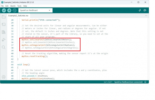
Notice the following code snippet - this is the section of code that allows you to choose your units:
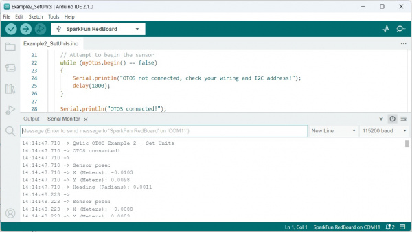
Make sure you've selected the correct board and port in the Tools menu and then hit the upload button. Once the code has finished uploading, go ahead and open a Serial Monitor. You should see something similar to the following.
Example 3: Calibration
The data from the OTOS will likely have minor scaling errors that can be calibrated out. This is especially important for the angular scalar, because an incorrect angle measurement causes the linear measurements to be rotated by the wrong angle in the firmware, which can lead to very inaccurate tracking.
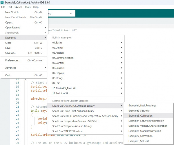
To find Example 3, go to File > Examples > SparkFun Qwiic OTOS > Example3_Calibration:
Alternatively, you can expand the link below and copy and paste the code into a shiny new Arduino sketch:
/*
    SPDX-License-Identifier: MIT

    Copyright (c) 2024 SparkFun Electronics
*/

/*******************************************************************************
    Example 3 - Calibration

    This example demonstrates how to calibrate the SparkFun Qwiic Optical
    Tracking Odometry Sensor (OTOS).

    This example should be used to calibrate the linear and angular scalars of
    the OTOS to get the most accurate tracking performance. The linear scalar
    can be used to compensate for scaling issues with the x and y measurements,
    while the angular scalar can be used to compensate for scaling issues with
    the heading measurement. Note that if the heading measurement is off, that
    can also cause the x and y measurements to be off, so it's recommended to
    calibrate the angular scalar first.
*******************************************************************************/

#include "SparkFun_Qwiic_OTOS_Arduino_Library.h"
#include "Wire.h"

// Create an Optical Tracking Odometry Sensor object
QwiicOTOS myOtos;

void setup()
{
    // Start serial
    Serial.begin(115200);
    Serial.println("Qwiic OTOS Example 3 - Calibration");

    Wire.begin();

    // Attempt to begin the sensor
    while (myOtos.begin() == false)
    {
        Serial.println("OTOS not connected, check your wiring and I2C address!");
        delay(1000);
    }

    Serial.println("OTOS connected!");

    Serial.println("Ensure the OTOS is flat and stationary, then enter any key to calibrate the IMU");

    // Clear the serial buffer
    while (Serial.available())
        Serial.read();
    // Wait for user input
    while (!Serial.available())
        ;

    Serial.println("Calibrating IMU...");

    // The IMU on the OTOS includes a gyroscope and accelerometer, which could
    // have an offset. Note that as of firmware version 1.0, the calibration
    // will be lost after a power cycle; the OTOS performs a quick calibration
    // when it powers up, but it is recommended to perform a more thorough
    // calibration at the start of all your programs. Note that the sensor must
    // be completely stationary and flat during calibration! When calling
    // calibrateImu(), you can specify the number of samples to take and whether
    // to wait until the calibration is complete. If no parameters are provided,
    // it will take 255 samples and wait until done; each sample takes about
    // 2.4ms, so about 612ms total
    myOtos.calibrateImu();

    // Alternatively, you can specify the number of samples and whether to wait
    // until it's done. If you don't want to wait, you can asynchronously check
    // how many samples remain with the code below. Once zero samples remain,
    // the calibration is done!
    // myOtos.calibrateImu(255, false);
    // bool done = false;
    // while(done == false)
    // {
    //     // Check how many samples remain
    //     uint8_t samplesRemaining;
    //     myOtos.getImuCalibrationProgress(samplesRemaining);

    //     // If 0 samples remain, the calibration is done
    //     if(samplesRemaining == 0)
    //         done = true;
    // }

    // Here we can set the linear and angular scalars, which can compensate for
    // scaling issues with the sensor measurements. Note that as of firmware
    // version 1.0, these values will be lost after a power cycle, so you will
    // need to set them each time you power up the sensor. They can be any value
    // from 0.872 to 1.127 in increments of 0.001 (0.1%). It is recommended to
    // first set both scalars to 1.0, then calibrate the angular scalar, then
    // the linear scalar. To calibrate the angular scalar, spin the robot by
    // multiple rotations (eg. 10) to get a precise error, then set the scalar
    // to the inverse of the error. Remember that the angle wraps from -180 to
    // 180 degrees, so for example, if after 10 rotations counterclockwise
    // (positive rotation), the sensor reports -15 degrees, the required scalar
    // would be 3600/3585 = 1.004. To calibrate the linear scalar, move the
    // robot a known distance and measure the error; do this multiple times at
    // multiple speeds to get an average, then set the linear scalar to the
    // inverse of the error. For example, if you move the robot 100 inches and
    // the sensor reports 103 inches, set the linear scalar to 100/103 = 0.971
    myOtos.setLinearScalar(1.0);
    myOtos.setAngularScalar(1.0);

    // Reset the tracking algorithm - this resets the position to the origin,
    // but can also be used to recover from some rare tracking errors
    myOtos.resetTracking();
}

void loop()
{
    // Get the latest position, which includes the x and y coordinates, plus the
    // heading angle
    sfe_otos_pose2d_t myPosition;
    myOtos.getPosition(myPosition);

    // Print measurement
    Serial.println();
    Serial.println("Position:");
    Serial.print("X (Inches): ");
    Serial.println(myPosition.x);
    Serial.print("Y (Inches): ");
    Serial.println(myPosition.y);
    Serial.print("Heading (Degrees): ");
    Serial.println(myPosition.h);

    // Wait a bit so we don't spam the serial port
    delay(500);

}
Make sure you've selected the correct board and port in the Tools menu and then hit the upload button. Once the code has finished uploading, go ahead and open a Serial Monitor.
Calibrating your bot requires you to move it around a bit. First, set both scalars to 1.0, then calibrate the angular scalar, then the linear scalar.
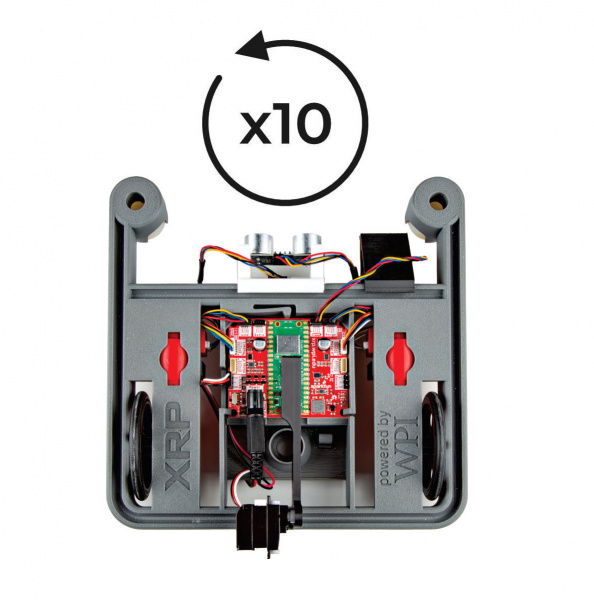
To calibrate the angular scalar, spin the robot by multiple rotations (eg. 10) to get a precise error, then set the scalar to the inverse of the error. Remember that the angle wraps from -180 to 180 degrees, so for example, if after 10 rotations counterclockwise(positive rotation), the sensor reports -15 degrees, the required scalar would be 3600/3585 = 1.004.
To calibrate the linear scalar, move the robot a known distance and measure the error; do this multiple times at multiple speeds to get an average, then set the linear scalar to the inverse of the error. For example, if you move the robot 100 inches and the sensor reports 103 inches, set the linear scalar to 100/103 = 0.971.
Example 4: SetOffsetAndPosition
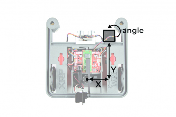
This example shows how to set the offset for the sensor relative to the center of the robot. The units default to inches and degrees, but if you want to use different units, make sure you specify them before setting the offset. Without setting the offset, the OTOS will report the coordinates of itself. If the offset is set, the OTOS will instead report the coordinates of the center of your robot.
Note that the OTOS typically starts tracking from the origin, but if your robot starts at some other location, or you have another source of location information from another sensor that's more accurate, you can send the current location to the OTOS and it will continue tracking from there.
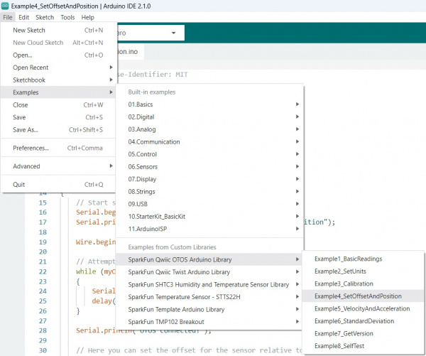
To find Example 4, go to File > Examples > SparkFun Qwiic OTOS > Example4_SetOffsetAndPosition:
Alternatively, you can expand the link below and copy and paste the code into a shiny new Arduino sketch:
/*
    SPDX-License-Identifier: MIT

    Copyright (c) 2024 SparkFun Electronics
*/

/*******************************************************************************
    Example 4 - Set Offset and Position

    This example demonstrates how to set the offset and position of the SparkFun
    Qwiic Optical Tracking Odometry Sensor (OTOS).

    If your OTOS is mounted to a robot and is not centered, you can specify the
    offset for the sensor relative to the center of the robot; rather than
    returning the position of the sensor, the OTOS will calculate and return the
    position of the robot's center. If you know where your robot is located,
    such as the starting location or from another sensor, you can send that
    position to the OTOS and it will continue to track from there.
*******************************************************************************/

#include "SparkFun_Qwiic_OTOS_Arduino_Library.h"
#include "Wire.h"

// Create an Optical Tracking Odometry Sensor object
QwiicOTOS myOtos;

void setup()
{
    // Start serial
    Serial.begin(115200);
    Serial.println("Qwiic OTOS Example 4 - Set Offset and Position");

    Wire.begin();

    // Attempt to begin the sensor
    while (myOtos.begin() == false)
    {
        Serial.println("OTOS not connected, check your wiring and I2C address!");
        delay(1000);
    }

    Serial.println("OTOS connected!");

    Serial.println("Ensure the OTOS is flat and stationary, then enter any key to calibrate the IMU");

    // Clear the serial buffer
    while (Serial.available())
        Serial.read();
    // Wait for user input
    while (!Serial.available())
        ;

    Serial.println("Calibrating IMU...");

    // Calibrate the IMU, which removes the accelerometer and gyroscope offsets
    myOtos.calibrateImu();

    // Assuming you've mounted your sensor to a robot and it's not centered,
    // you can specify the offset for the sensor relative to the center of the
    // robot. The units default to inches and degrees, but if you want to use
    // different units, specify them before setting the offset! Note that as of
    // firmware version 1.0, these values will be lost after a power cycle, so
    // you will need to set them each time you power up the sensor. For example, if
    // the sensor is mounted 5 inches to the left (negative X) and 10 inches
    // forward (positive Y) of the center of the robot, and mounted 90 degrees
    // clockwise (negative rotation) from the robot's orientation, the offset
    // would be {-5, 10, -90}. These can be any value, even the angle can be
    // tweaked slightly to compensate for imperfect mounting (eg. 1.3 degrees).
    sfe_otos_pose2d_t offset = {-5, 10, -90};
    myOtos.setOffset(offset);

    // Reset the tracking algorithm - this resets the position to the origin,
    // but can also be used to recover from some rare tracking errors
    myOtos.resetTracking();

    // After resetting the tracking, the OTOS will report that the robot is at
    // the origin. If your robot does not start at the origin, or you have
    // another source of location information (eg. vision odometry), you can set
    // the OTOS location to match and it will continue to track from there.
    sfe_otos_pose2d_t currentPosition = {0, 0, 0};
    myOtos.setPosition(currentPosition);
}

void loop()
{
    // Get the latest position, which includes the x and y coordinates, plus the
    // heading angle
    sfe_otos_pose2d_t myPosition;
    myOtos.getPosition(myPosition);

    // Print measurement
    Serial.println();
    Serial.println("Position:");
    Serial.print("X (Inches): ");
    Serial.println(myPosition.x);
    Serial.print("Y (Inches): ");
    Serial.println(myPosition.y);
    Serial.print("Heading (Degrees): ");
    Serial.println(myPosition.h);

    // Wait a bit so we don't spam the serial port
    delay(500);

}
If the sensor is mounted 5 inches to the left (negative X) and 10 inches forward (positive Y) of the center of the robot, and mounted 90 degrees clockwise (negative rotation) from the robot's orientation, the offset would be {-5, 10, -90}. These can be any value, even the angle can be tweaked slightly to compensate for imperfect mounting (eg. 1.3 degrees).
These four examples cover the basics - there are more examples to explore in the library!
Python Examples & Calibration
Download Examples
First, go to the Qwiic_OTOS_Py repository, open the examples folder, and download the example files you want to run.
Connect your XRP to your computer over USB, navigate to the XRPCode editor, and connect to your XRP. For usage information, see the XRPCode User Guide.
Upload the example files into the root directory (/), or directory of your choice, on the XRP. Begin by finding the Upload to XRP option:
Upload to XRP option in the File Menu Select the files to upload:
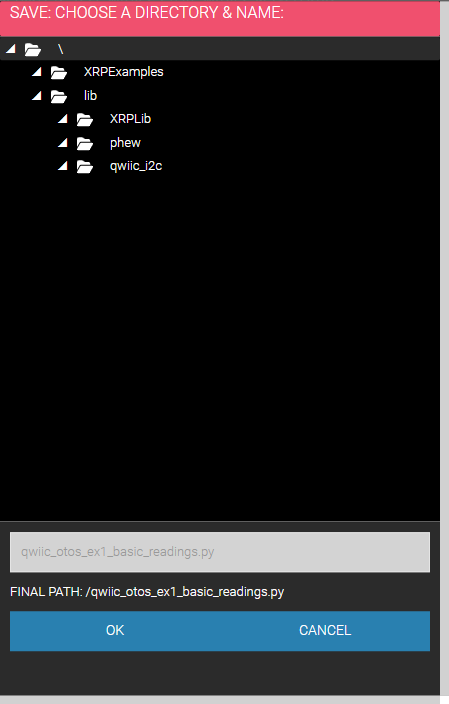
Select the root directory (/), or directory of your choice, on the XRP:
Click the OK button and wait for the files to upload and save:
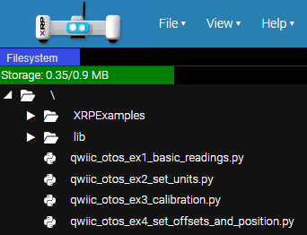
You should then see the examples in the Filesystem panel on the left:
Example 1: Basic Readings
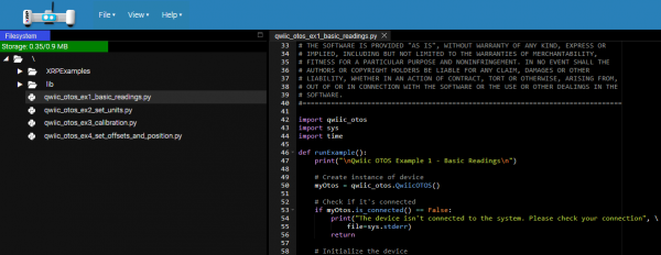
This first example just does some basic measurements to make sure everything is hooked up correctly. Assuming you uploaded this example in the procedure above, double-click qwiic_otos_ex1_basic_readings.py in the Filesystem panel on the left:
qwiic_otos_ex1_basic_readings.py XRP File Location Alternatively, you can expand the link below and copy and paste the code into a shiny new file:
#!/usr/bin/env python
#-------------------------------------------------------------------------------
# qwiic_otos_ex1_basic_readings.py
#
# This example demonstrates how to read the position and heading from the
# SparkFun Qwiic Optical Tracking Odometry Sensor (OTOS).
#
# This example should be used to verify that the OTOS is connected and
# functioning correctly. It will just print the position and heading tracked
# by the OTOS to the serial monitor. It is recommended that you check out the
# other examples before using the OTOS in your own project.
#-------------------------------------------------------------------------------
# Written by SparkFun Electronics, May 2024
#
# This python library supports the SparkFun Electroncis Qwiic ecosystem
#
# More information on Qwiic is at https://www.sparkfun.com/qwiic
#
# Do you like this library? Help support SparkFun. Buy a board!
#===============================================================================
# Copyright (c) 2023 SparkFun Electronics
#
# Permission is hereby granted, free of charge, to any person obtaining a copy
# of this software and associated documentation files (the "Software"), to deal
# in the Software without restriction, including without limitation the rights
# to use, copy, modify, merge, publish, distribute, sublicense, and/or sell
# copies of the Software, and to permit persons to whom the Software is
# furnished to do so, subject to the following conditions:
#
# The above copyright notice and this permission notice shall be included in all
# copies or substantial portions of the Software.
#
# THE SOFTWARE IS PROVIDED "AS IS", WITHOUT WARRANTY OF ANY KIND, EXPRESS OR
# IMPLIED, INCLUDING BUT NOT LIMITED TO THE WARRANTIES OF MERCHANTABILITY,
# FITNESS FOR A PARTICULAR PURPOSE AND NONINFRINGEMENT. IN NO EVENT SHALL THE
# AUTHORS OR COPYRIGHT HOLDERS BE LIABLE FOR ANY CLAIM, DAMAGES OR OTHER
# LIABILITY, WHETHER IN AN ACTION OF CONTRACT, TORT OR OTHERWISE, ARISING FROM,
# OUT OF OR IN CONNECTION WITH THE SOFTWARE OR THE USE OR OTHER DEALINGS IN THE
# SOFTWARE.
#===============================================================================

import qwiic_otos
import sys
import time

def runExample():
    print("\nQwiic OTOS Example 1 - Basic Readings\n")

    # Create instance of device
    myOtos = qwiic_otos.QwiicOTOS()

    # Check if it's connected
    if myOtos.is_connected() == False:
        print("The device isn't connected to the system. Please check your connection", \
            file=sys.stderr)
        return

    # Initialize the device
    myOtos.begin()

    print("Ensure the OTOS is flat and stationary during calibration!")
    for i in range(5, 0, -1):
        print("Calibrating in %d seconds..." % i)
        time.sleep(1)

    print("Calibrating IMU...")

    # Calibrate the IMU, which removes the accelerometer and gyroscope offsets
    myOtos.calibrateImu()

    # Reset the tracking algorithm - this resets the position to the origin,
    # but can also be used to recover from some rare tracking errors
    myOtos.resetTracking()

    # Main loop
    while True:
        # Get the latest position, which includes the x and y coordinates, plus
        # the heading angle
        myPosition = myOtos.getPosition()

        # Print measurement
        print()
        print("Position:")
        print("X (Inches): {}".format(myPosition.x))
        print("Y (Inches): {}".format(myPosition.y))
        print("Heading (Degrees): {}".format(myPosition.h))

        # Wait a bit so we don't spam the serial port
        time.sleep(0.5)

        # Alternatively, you can comment out the print and delay code above, and
        # instead use the following code to rapidly refresh the data
        # print("{}\t{}\t{}".format(myPosition.x, myPosition.y, myPosition.h))
        # time.sleep(0.01)

if __name__ == '__main__':
    try:
        runExample()
    except (KeyboardInterrupt, SystemExit) as exErr:
        print("\nEnding Example")
        sys.exit(0)
Then click the run button in the top right corner:
You should see the following output in the Shell:
Move the sensor around to see how the coordinates change!
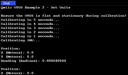
Example 2: Set Units
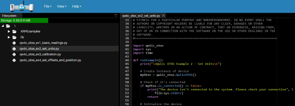
This example sets the desired units for linear and angular measurements. Can be either meters or inches for linear, and radians or degrees for angular. If not set, the default is inches and degrees. Note that this setting is not stored in the sensor, it's part of the library, so you need to set at the start of all your programs. Assuming you uploaded this example in the procedure above, double-click qwiic_otos_ex2_set_units.py in the Filesystem panel on the left:
qwiic_otos_ex2_set_units.py XRP File Location Alternatively, you can expand the link below and copy and paste the code into a shiny new file and upload to the XRP as described above.
#!/usr/bin/env python
#-------------------------------------------------------------------------------
# qwiic_otos_ex2_set_units.py
#
# This example demonstrates how to change the units of the SparkFun Qwiic
# Optical Tracking Odometry Sensor (OTOS).

# The OTOS library defaults to inches and degrees, but you can change the
# units to suit the needs of your project.
#-------------------------------------------------------------------------------
# Written by SparkFun Electronics, May 2024
#
# This python library supports the SparkFun Electroncis Qwiic ecosystem
#
# More information on Qwiic is at https://www.sparkfun.com/qwiic
#
# Do you like this library? Help support SparkFun. Buy a board!
#===============================================================================
# Copyright (c) 2023 SparkFun Electronics
#
# Permission is hereby granted, free of charge, to any person obtaining a copy
# of this software and associated documentation files (the "Software"), to deal
# in the Software without restriction, including without limitation the rights
# to use, copy, modify, merge, publish, distribute, sublicense, and/or sell
# copies of the Software, and to permit persons to whom the Software is
# furnished to do so, subject to the following conditions:
#
# The above copyright notice and this permission notice shall be included in all
# copies or substantial portions of the Software.
#
# THE SOFTWARE IS PROVIDED "AS IS", WITHOUT WARRANTY OF ANY KIND, EXPRESS OR
# IMPLIED, INCLUDING BUT NOT LIMITED TO THE WARRANTIES OF MERCHANTABILITY,
# FITNESS FOR A PARTICULAR PURPOSE AND NONINFRINGEMENT. IN NO EVENT SHALL THE
# AUTHORS OR COPYRIGHT HOLDERS BE LIABLE FOR ANY CLAIM, DAMAGES OR OTHER
# LIABILITY, WHETHER IN AN ACTION OF CONTRACT, TORT OR OTHERWISE, ARISING FROM,
# OUT OF OR IN CONNECTION WITH THE SOFTWARE OR THE USE OR OTHER DEALINGS IN THE
# SOFTWARE.
#===============================================================================

import qwiic_otos
import sys
import time

def runExample():
    print("\nQwiic OTOS Example 2 - Set Units\n")

    # Create instance of device
    myOtos = qwiic_otos.QwiicOTOS()

    # Check if it's connected
    if myOtos.is_connected() == False:
        print("The device isn't connected to the system. Please check your connection", \
            file=sys.stderr)
        return

    # Initialize the device
    myOtos.begin()

    print("Ensure the OTOS is flat and stationary during calibration!")
    for i in range(5, 0, -1):
        print("Calibrating in %d seconds..." % i)
        time.sleep(1)

    print("Calibrating IMU...")

    # Calibrate the IMU, which removes the accelerometer and gyroscope offsets
    myOtos.calibrateImu()

    # Set the desired units for linear and angular measurements. Can be either
    # meters or inches for linear, and radians or degrees for angular. If not
    # set, the default is inches and degrees. Note that this setting is not
    # stored in the sensor, it's part of the library, so you need to set at the
    # start of all your programs.
    myOtos.setLinearUnit(myOtos.kLinearUnitMeters)
    # myOtos.setLinearUnit(myOtos.kLinearUnitInches)
    myOtos.setAngularUnit(myOtos.kAngularUnitRadians)
    # myOtos.setAngularUnit(myOtos.kAngularUnitDegrees)

    # Reset the tracking algorithm - this resets the position to the origin,
    # but can also be used to recover from some rare tracking errors
    myOtos.resetTracking()

    # Main loop
    while True:
        # Get the latest position, which includes the x and y coordinates, plus
        # the heading angle
        myPosition = myOtos.getPosition()

        # Print measurement
        print()
        print("Position:")
        print("X (Meters): {}".format(myPosition.x))
        print("Y (Meters): {}".format(myPosition.y))
        print("Heading (Radians): {}".format(myPosition.h))

        # Wait a bit so we don't spam the serial port
        time.sleep(0.5)

if __name__ == '__main__':
    try:
        runExample()
    except (KeyboardInterrupt, SystemExit) as exErr:
        print("\nEnding Example")
        sys.exit(0)
Notice the following code snippet - this is the section of code that allows you to choose your units:
Then click the run button in the top right corner:
You should see the following output in the Shell:
Example 3: Calibration
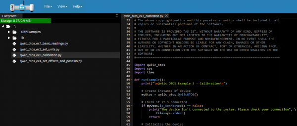
The data from the OTOS will likely have minor scaling errors that can be calibrated out. This is especially important for the angular scalar, because an incorrect angle measurement causes the linear measurements to be rotated by the wrong angle in the firmware, which can lead to very inaccurate tracking. Assuming you uploaded this example in the procedure above, double-click qwiic_otos_ex3_calibration.py in the Filesystem panel on the left:
qwiic_otos_ex3_calibration.py XRP File Location Alternatively, you can expand the link below and copy and paste the code into a shiny new file and upload to the XRP as described above.
#!/usr/bin/env python
#-------------------------------------------------------------------------------
# qwiic_otos_ex3_calibration.py
#
# This example demonstrates how to calibrate the SparkFun Qwiic Optical
# Tracking Odometry Sensor (OTOS).

# This example should be used to calibrate the linear and angular scalars of
# the OTOS to get the most accurate tracking performance. The linear scalar
# can be used to compensate for scaling issues with the x and y measurements,
# while the angular scalar can be used to compensate for scaling issues with
# the heading measurement. Note that if the heading measurement is off, that
# can also cause the x and y measurements to be off, so it's recommended to
# calibrate the angular scalar first.
#-------------------------------------------------------------------------------
# Written by SparkFun Electronics, May 2024
#
# This python library supports the SparkFun Electroncis Qwiic ecosystem
#
# More information on Qwiic is at https:#www.sparkfun.com/qwiic
#
# Do you like this library? Help support SparkFun. Buy a board!
#===============================================================================
# Copyright (c) 2023 SparkFun Electronics
#
# Permission is hereby granted, free of charge, to any person obtaining a copy
# of this software and associated documentation files (the "Software"), to deal
# in the Software without restriction, including without limitation the rights
# to use, copy, modify, merge, publish, distribute, sublicense, and/or sell
# copies of the Software, and to permit persons to whom the Software is
# furnished to do so, subject to the following conditions:
#
# The above copyright notice and this permission notice shall be included in all
# copies or substantial portions of the Software.
#
# THE SOFTWARE IS PROVIDED "AS IS", WITHOUT WARRANTY OF ANY KIND, EXPRESS OR
# IMPLIED, INCLUDING BUT NOT LIMITED TO THE WARRANTIES OF MERCHANTABILITY,
# FITNESS FOR A PARTICULAR PURPOSE AND NONINFRINGEMENT. IN NO EVENT SHALL THE
# AUTHORS OR COPYRIGHT HOLDERS BE LIABLE FOR ANY CLAIM, DAMAGES OR OTHER
# LIABILITY, WHETHER IN AN ACTION OF CONTRACT, TORT OR OTHERWISE, ARISING FROM,
# OUT OF OR IN CONNECTION WITH THE SOFTWARE OR THE USE OR OTHER DEALINGS IN THE
# SOFTWARE.
#===============================================================================

import qwiic_otos
import sys
import time

def runExample():
    print("\nQwiic OTOS Example 3 - Calibration\n")

    # Create instance of device
    myOtos = qwiic_otos.QwiicOTOS()

    # Check if it's connected
    if myOtos.is_connected() == False:
        print("The device isn't connected to the system. Please check your connection", \
            file=sys.stderr)
        return

    # Initialize the device
    myOtos.begin()

    print("Ensure the OTOS is flat and stationary during calibration!")
    for i in range(5, 0, -1):
        print("Calibrating in %d seconds..." % i)
        time.sleep(1)

    print("Calibrating IMU...")

    # The IMU on the OTOS includes a gyroscope and accelerometer, which could
    # have an offset. Note that as of firmware version 1.0, the calibration
    # will be lost after a power cycle; the OTOS performs a quick calibration
    # when it powers up, but it is recommended to perform a more thorough
    # calibration at the start of all your programs. Note that the sensor must
    # be completely stationary and flat during calibration! When calling
    # calibrateImu(), you can specify the number of samples to take and whether
    # to wait until the calibration is complete. If no parameters are provided,
    # it will take 255 samples and wait until done; each sample takes about
    # 2.4ms, so about 612ms total
    myOtos.calibrateImu()

    # Alternatively, you can specify the number of samples and whether to wait
    # until it's done. If you don't want to wait, you can asynchronously check
    # how many samples remain with the code below. Once zero samples remain,
    # the calibration is done!
    # myOtos.calibrateImu(255, False)
    # done = False
    # while(done == False):
    #     # Check how many samples remain
    #     samplesRemaining = myOtos.getImuCalibrationProgress()

    #     # If 0 samples remain, the calibration is done
    #     if(samplesRemaining == 0):
    #         done = True

    # Here we can set the linear and angular scalars, which can compensate for
    # scaling issues with the sensor measurements. Note that as of firmware
    # version 1.0, these values will be lost after a power cycle, so you will
    # need to set them each time you power up the sensor. They can be any value
    # from 0.872 to 1.127 in increments of 0.001 (0.1%). It is recommended to
    # first set both scalars to 1.0, then calibrate the angular scalar, then
    # the linear scalar. To calibrate the angular scalar, spin the robot by
    # multiple rotations (eg. 10) to get a precise error, then set the scalar
    # to the inverse of the error. Remember that the angle wraps from -180 to
    # 180 degrees, so for example, if after 10 rotations counterclockwise
    # (positive rotation), the sensor reports -15 degrees, the required scalar
    # would be 3600/3585 = 1.004. To calibrate the linear scalar, move the
    # robot a known distance and measure the error; do this multiple times at
    # multiple speeds to get an average, then set the linear scalar to the
    # inverse of the error. For example, if you move the robot 100 inches and
    # the sensor reports 103 inches, set the linear scalar to 100/103 = 0.971
    myOtos.setLinearScalar(1.0)
    myOtos.setAngularScalar(1.0)

    # Reset the tracking algorithm - this resets the position to the origin,
    # but can also be used to recover from some rare tracking errors
    myOtos.resetTracking()

    # Main loop
    while True:
        # Get the latest position, which includes the x and y coordinates, plus
        # the heading angle
        myPosition = myOtos.getPosition()

        # Print measurement
        print()
        print("Position:")
        print("X (Inches): {}".format(myPosition.x))
        print("Y (Inches): {}".format(myPosition.y))
        print("Heading (Degrees): {}".format(myPosition.h))

        # Wait a bit so we don't spam the serial port
        time.sleep(0.5)

if __name__ == '__main__':
    try:
        runExample()
    except (KeyboardInterrupt, SystemExit) as exErr:
        print("\nEnding Example")
        sys.exit(0)
Then click the run button in the top right corner:
Calibrating your bot requires you to move it around a bit. First, set both scalars to 1.0, then calibrate the angular scalar, then the linear scalar.
To calibrate the angular scalar, spin the robot by multiple rotations (eg. 10) to get a precise error, then set the scalar to the inverse of the error. Remember that the angle wraps from -180 to 180 degrees, so for example, if after 10 rotations counterclockwise(positive rotation), the sensor reports -15 degrees, the required scalar would be 3600/3585 = 1.004.
To calibrate the linear scalar, move the robot a known distance and measure the error; do this multiple times at multiple speeds to get an average, then set the linear scalar to the inverse of the error. For example, if you move the robot 100 inches and the sensor reports 103 inches, set the linear scalar to 100/103 = 0.971.
Example 4: SetOffsetAndPosition
This example shows how to set the offset for the sensor relative to the center of the robot. The units default to inches and degrees, but if you want to use different units, make sure you specify them before setting the offset. Without setting the offset, the OTOS will report the coordinates of itself. If the offset is set, the OTOS will instead report the coordinates of the center of your robot.
Note that the OTOS typically starts tracking from the origin, but if your robot starts at some other location, or you have another source of location information from another sensor that's more accurate, you can send the current location to the OTOS and it will continue tracking from there.
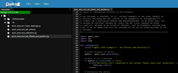
Assuming you uploaded this example in the procedure above, double-click qwiic_otos_ex4_set_offsets_and_position.py in the Filesystem panel on the left:
qwiic_otos_ex4_set_offsets_and_position.py XRP File Location Alternatively, you can expand the link below and copy and paste the code into a shiny new file and upload to the XRP as described above.
#!/usr/bin/env python
#-------------------------------------------------------------------------------
# qwiic_otos_ex4_set_offsets_and_position.py
#
# This example demonstrates how to set the offset and position of the SparkFun
# Qwiic Optical Tracking Odometry Sensor (OTOS).

# If your OTOS is mounted to a robot and is not centered, you can specify the
# offset for the sensor relative to the center of the robot; rather than
# returning the position of the sensor, the OTOS will calculate and return the
# position of the robot's center. If you know where your robot is located,
# such as the starting location or from another sensor, you can send that
# position to the OTOS and it will continue to track from there.
#-------------------------------------------------------------------------------
# Written by SparkFun Electronics, May 2024
#
# This python library supports the SparkFun Electroncis Qwiic ecosystem
#
# More information on Qwiic is at https:#www.sparkfun.com/qwiic
#
# Do you like this library? Help support SparkFun. Buy a board!
#===============================================================================
# Copyright (c) 2023 SparkFun Electronics
#
# Permission is hereby granted, free of charge, to any person obtaining a copy
# of this software and associated documentation files (the "Software"), to deal
# in the Software without restriction, including without limitation the rights
# to use, copy, modify, merge, publish, distribute, sublicense, and/or sell
# copies of the Software, and to permit persons to whom the Software is
# furnished to do so, subject to the following conditions:
#
# The above copyright notice and this permission notice shall be included in all
# copies or substantial portions of the Software.
#
# THE SOFTWARE IS PROVIDED "AS IS", WITHOUT WARRANTY OF ANY KIND, EXPRESS OR
# IMPLIED, INCLUDING BUT NOT LIMITED TO THE WARRANTIES OF MERCHANTABILITY,
# FITNESS FOR A PARTICULAR PURPOSE AND NONINFRINGEMENT. IN NO EVENT SHALL THE
# AUTHORS OR COPYRIGHT HOLDERS BE LIABLE FOR ANY CLAIM, DAMAGES OR OTHER
# LIABILITY, WHETHER IN AN ACTION OF CONTRACT, TORT OR OTHERWISE, ARISING FROM,
# OUT OF OR IN CONNECTION WITH THE SOFTWARE OR THE USE OR OTHER DEALINGS IN THE
# SOFTWARE.
#===============================================================================

import qwiic_otos
import sys
import time

def runExample():
    print("\nQwiic OTOS Example 4 - Set Offsets and Position\n")

    # Create instance of device
    myOtos = qwiic_otos.QwiicOTOS()

    # Check if it's connected
    if myOtos.is_connected() == False:
        print("The device isn't connected to the system. Please check your connection", \
            file=sys.stderr)
        return

    # Initialize the device
    myOtos.begin()

    print("Ensure the OTOS is flat and stationary during calibration!")
    for i in range(5, 0, -1):
        print("Calibrating in %d seconds..." % i)
        time.sleep(1)

    print("Calibrating IMU...")

    # Calibrate the IMU, which removes the accelerometer and gyroscope offsets
    myOtos.calibrateImu()

    # Assuming you've mounted your sensor to a robot and it's not centered,
    # you can specify the offset for the sensor relative to the center of the
    # robot. The units default to inches and degrees, but if you want to use
    # different units, specify them before setting the offset! Note that as of
    # firmware version 1.0, these values will be lost after a power cycle, so
    # you will need to set them each time you power up the sensor. For example,
    # if the sensor is mounted 5 inches to the left (negative X) and 10 inches
    # forward (positive Y) of the center of the robot, and mounted 90 degrees
    # clockwise (negative rotation) from the robot's orientation, the offset
    # would be {-5, 10, -90}. These can be any value, even the angle can be
    # tweaked slightly to compensate for imperfect mounting (eg. 1.3 degrees).
    offset = qwiic_otos.Pose2D(-5, 10, -90)
    myOtos.setOffset(offset)

    # Reset the tracking algorithm - this resets the position to the origin,
    # but can also be used to recover from some rare tracking errors
    myOtos.resetTracking()

    # After resetting the tracking, the OTOS will report that the robot is at
    # the origin. If your robot does not start at the origin, or you have
    # another source of location information (eg. vision odometry), you can set
    # the OTOS location to match and it will continue to track from there.
    currentPosition = qwiic_otos.Pose2D(0, 0, 0)
    myOtos.setPosition(currentPosition)

    # Main loop
    while True:
        # Get the latest position, which includes the x and y coordinates, plus
        # the heading angle
        myPosition = myOtos.getPosition()

        # Print measurement
        print()
        print("Position:")
        print("X (Inches): {}".format(myPosition.x))
        print("Y (Inches): {}".format(myPosition.y))
        print("Heading (Degrees): {}".format(myPosition.h))

        # Wait a bit so we don't spam the serial port
        time.sleep(0.5)

if __name__ == '__main__':
    try:
        runExample()
    except (KeyboardInterrupt, SystemExit) as exErr:
        print("\nEnding Example")
        sys.exit(0)
Then click the run button in the top right corner:
If the sensor is mounted 5 inches to the left (negative X) and 10 inches forward (positive Y) of the center of the robot, and mounted 90 degrees clockwise (negative rotation) from the robot's orientation, the offset would be {-5, 10, -90}. These can be any value, even the angle can be tweaked slightly to compensate for imperfect mounting (eg. 1.3 degrees).
These four examples cover the basics - there are more examples to explore in the GitHub Repo!
Going Further and Other Resources
Below are a few tutorials that may help users familiarize themselves with various aspects of the board.
I2C
Serial Terminal Basics
The SparkFun Optical Tracking Odometry Sensor - PAA5160E1 (Qwiic) takes advantage of the Qwiic connect system. We recommend familiarizing yourself with the Logic Levels and I2C tutorials. Click on the banner above to learn more about Qwiic products.
