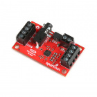
The SparkFun Audio Codec Breakout - WM8960 is a low power, high quality stereo codec with 1W Stereo Class D speaker drivers and headphone drivers. The WM8960 acts as a stereo audio ADC and DAC, and communicates using I2S, a standard audio data protocol (not to be confused with I2C). This audio codec is chock full of features some of which includes advanced on-chip digital signal processing for automatic level control (ALC) for the line or microphone input, programmable gain amplifier (PGA), pop and click suppression, and its ability to configure I2S settings and analog audio path through software via I2C.
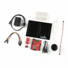
To follow along with this tutorial, you will need the following materials at a minimum. You may not need everything though depending on what you have. Add it to your cart, read through the guide, and adjust the cart as necessary. Note that the wishlist does not include any microphones or speakers.
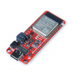
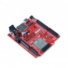
You will need an Arduino microcontroller to configure the WM8960. We recommend the Espressif's ESP32 WROOM. For the scope of this tutorial, we will be using the IoT RedBoard ESP32 - Development Board since it already includes female headers on the board to connect jumper wires to the WM8960.
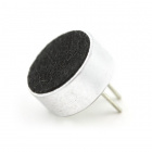
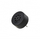
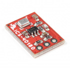
Below is a differential microphone from the catalog that you can connect as a differential microphone input. Note that you will need a resistor and the MICBIAS pin to connect to the eletret microphone.
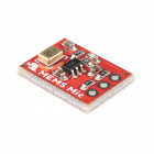
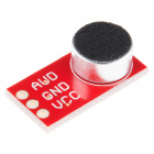
Below are a few electret and MEMS microphones from the catalog that you can connect as a single ended microphone input.
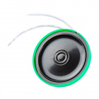
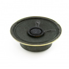
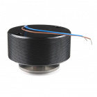
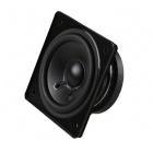
Below are a few speakers from the catalog that you could use as an output. You will want to choose differential speakers like the following listed below (not to be confused by the piezo buzzers). Note that some speakers may perform better than others at certain frequencies while others operate around a certain frequency range. Make sure to check out the speaker's datasheet when choosing a speaker.
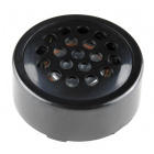
Note that some speakers may be rated as a higher wattage (more than what the Audio Codec's speaker driver can output). Higher wattage speakers will still play sound but they won't be fully powered.
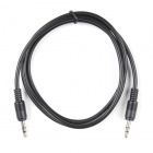
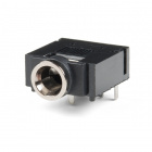
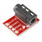
Depending on your setup, you may need an adapter or cable for the TRS audio connection for line level input or headphone output.
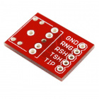
You can also use a TRRS breakout instead of the TRS breakout listed above. RING2 of the TRRS connector also connects to the TRS cable's sleeve. When wiring your circuit up, we recommend connecting to the sleeve in case you have a headphone with a TRRS connector.
You will need a soldering iron, solder, and general soldering accessories for a secure connection when using the plated through hole pads.
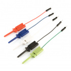
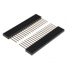
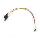
Depending on your setup, you may want to use IC hooks for a temporary connection. However, you will want to solder header pins to connect devices to the plated through holes for a secure connection. Note that you will need to breakaway the male header pins or cut the female header pins down to fit the two rows of 1x16 PTH on the breakout. Of course, you could also solder wire as well.
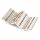
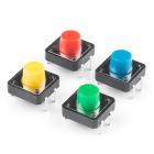
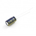
For users that are interested in adding an input to adjust volume or modes, you can add a trimpot and button to the setup. A few of the examples used in this tutorial use the trimpot to adjust. You will need to add a few lines of code if you want to toggle certain modes (i.e. 3D enhance, loopback, etc) or if you decided to use buttons to turn up or down the volume. For advanced users using their own differential microphones, you will need to add a 2.2kΩ resistor in series with each microphone. Other passives like capacitors may also be needed depending on your application.
For those that want to take advantage of the Qwiic enabled devices, you'll want to grab a Qwiic cable.


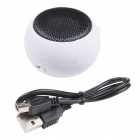
Depending on your setup, you will also need some sort of audio source. This can be from your smartphone or computer. Most of the examples listed in this tutorial will output the audio through the headphones. You will also need to have a pair of headphones with a 3.5mm TRS audio jack on the end.
If you aren't familiar with the MicroMod ecosystem, we recommend reading here for an overview if you decide to take advantage of the Qwiic connector.
 |
| Qwiic Connect System |
If you aren’t familiar with the following concepts, we also recommend checking out a few of these tutorials before continuing. Make sure to check the respective hookup guides for your microcontroller to ensure that you are installing the correct USB-to-serial converter. You may also need to follow additional instructions that are not outlined in this tutorial to install the appropriate software.
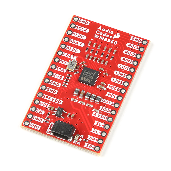
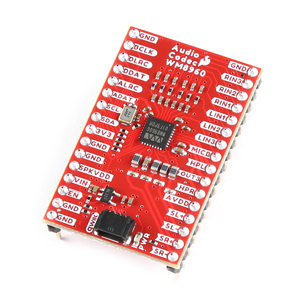
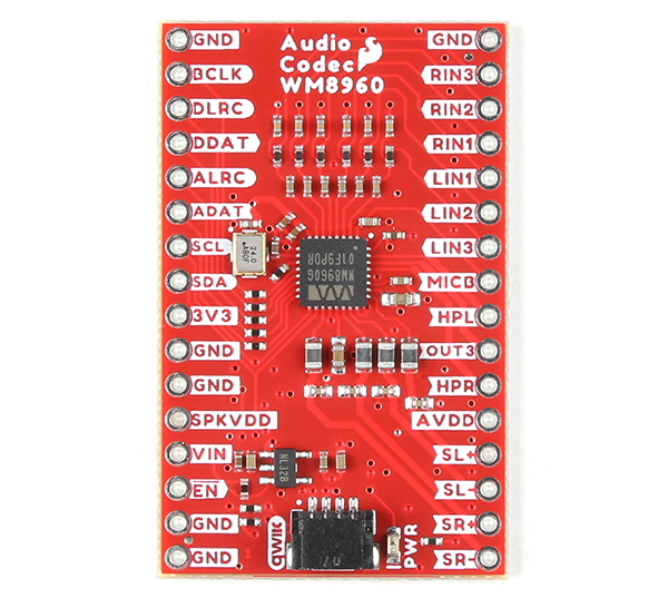
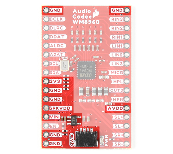
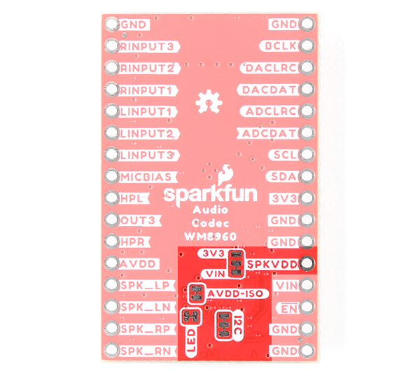
We broke out the pins of the WM8960 onto a breakout board to standard 0.1" spaced PTH. We'll highlight relevant application circuits, hardware, and pins that are broken out in this section.
 |
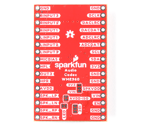 |
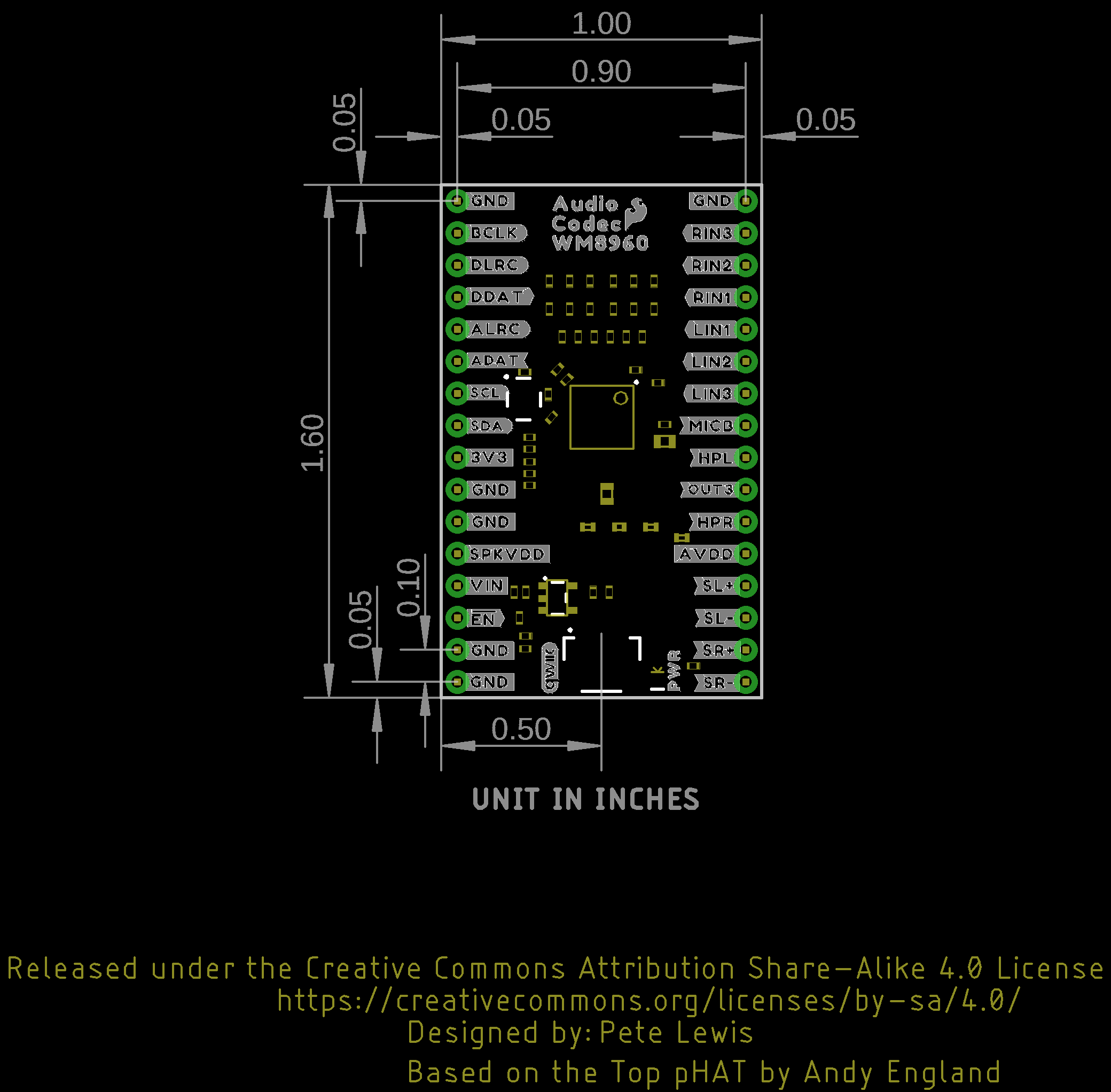
| Top View | Bottom View |
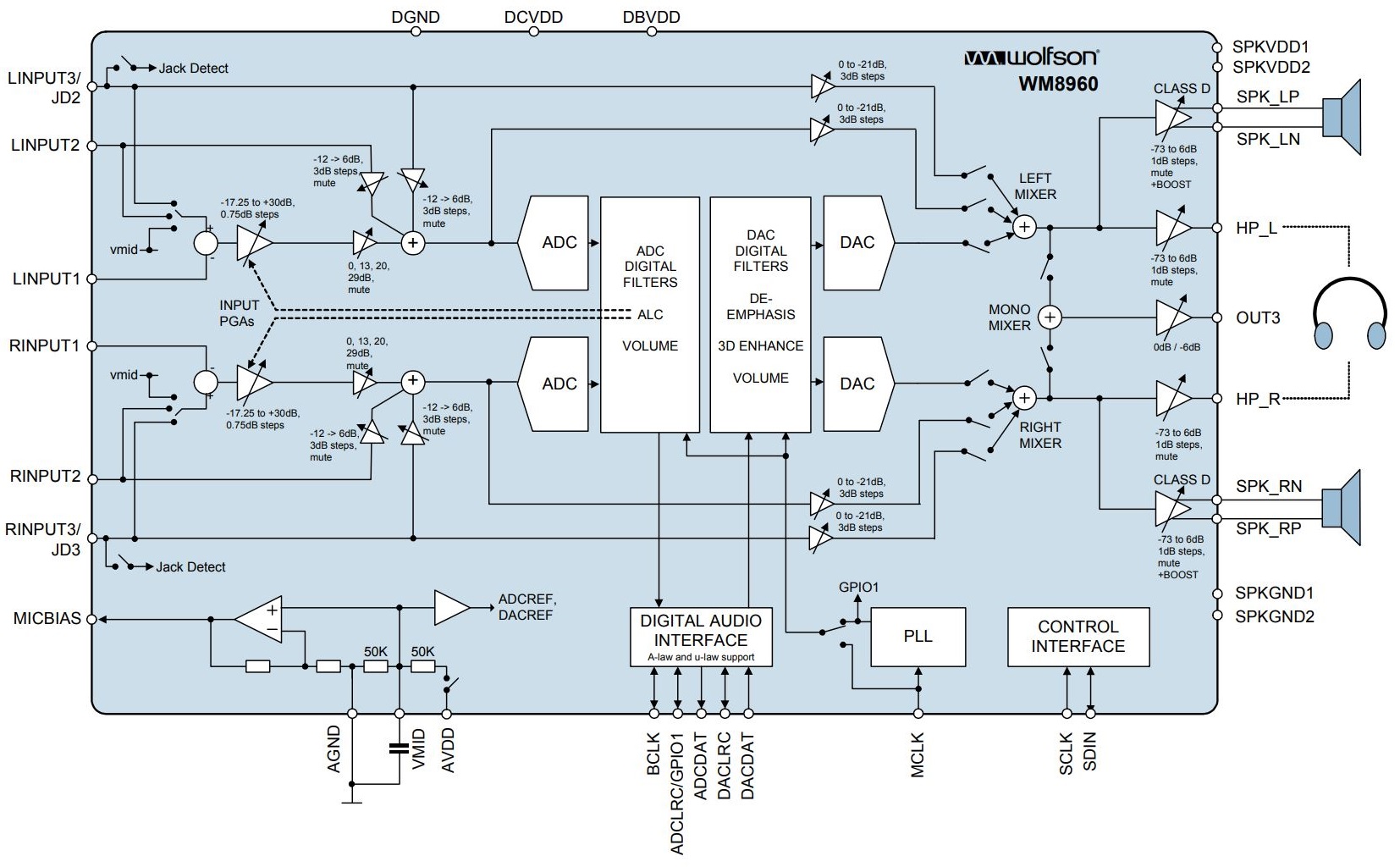
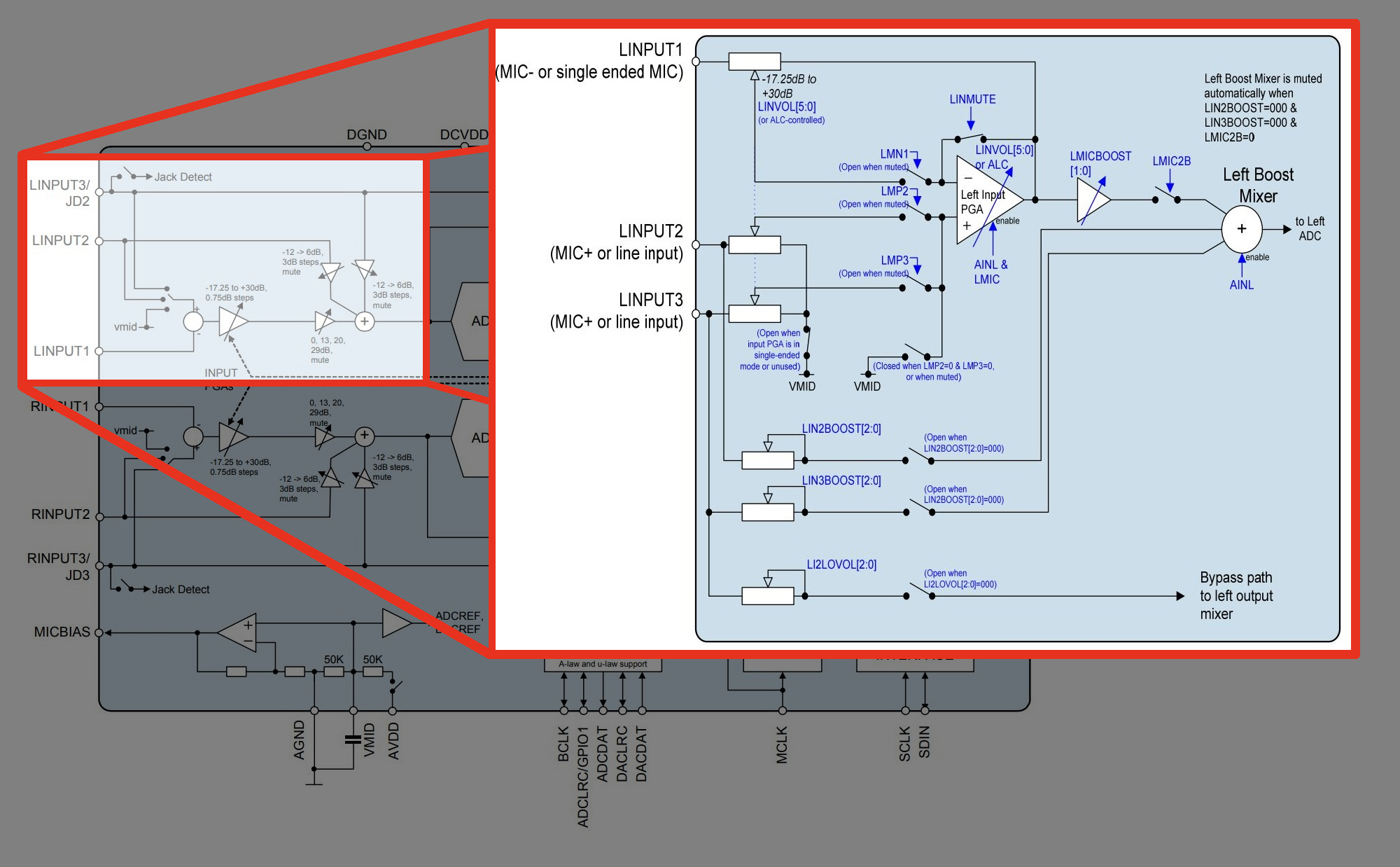
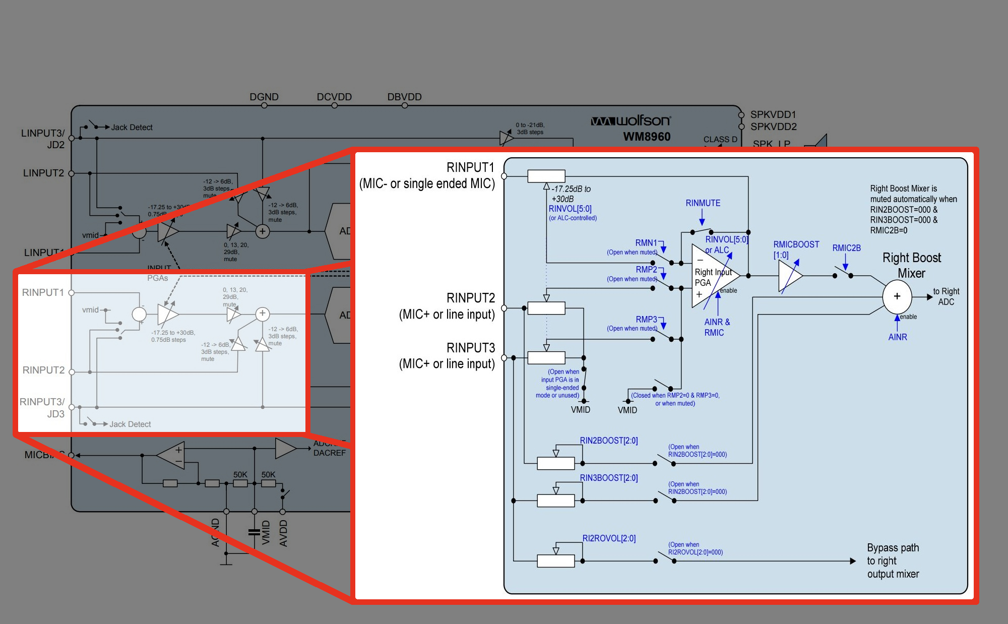
Keep in mind that the WM8960 is chock full of features as you can see from the datasheet's block diagram below. The input and output will depend on your project's needs. We recommend referencing the block diagrams listed in the datasheet to follow along. For more information, check out the datasheet linked in the Resources and Going Further.
There are a variety of power and power-related nets broken out to the Qwiic connector and through hole pads on the edge of the board. The nets consist of the following.
To get started powering the audio codec, you will just need to provide power to the VIN and 3V3 pins. We recommend using your development board's voltages without adjusting the jumpers. For example, the IoT RedBoard - ESP32 Development Board can provide 5V through the female header and 3.3V through the Qwiic connector. Users can connect 5V to the audio codec's VIN pin to power the analog and speaker circuit. To power the digital circuit, users can provide 3.3V by adding a Qwiic cable between the Qwiic connectors. Of course, you will need to also connect your reference voltage for your system. By using the Qwiic cable, you will be connecting GND on both boards.
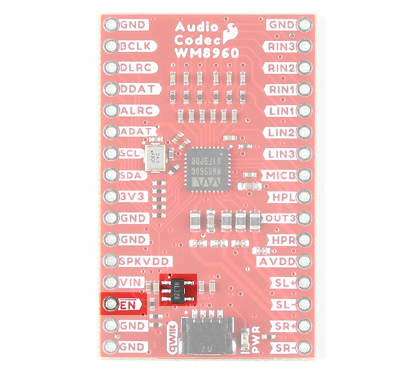
The enable pin (labeled as EN) on the edge of the board is active low. Pulling the pin low will disable the 3.3V voltage regulator XC6222 that is connected to AVDD.
The board breaks out pins for the digital audio interface. This is used for inputting DAC data into the WM8960 and outputting ADC data from the IC.
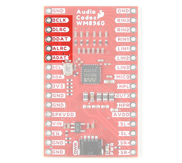
Four audio data formats listed below are supported.
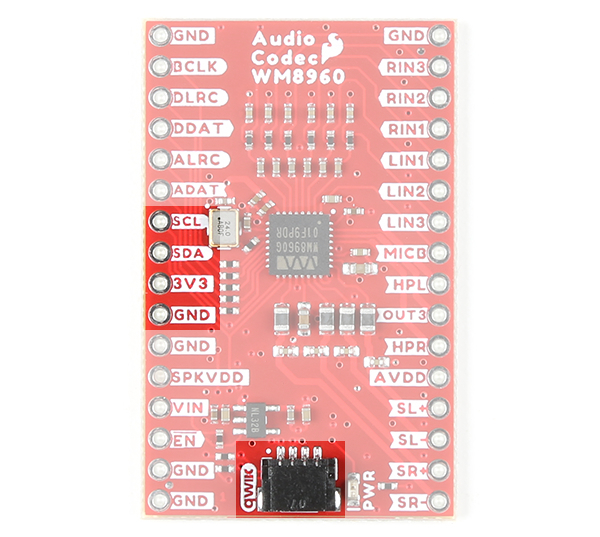
The board includes one Qwiic connector to configure the I2S settings and analog audio path. For users that need to solder directly to the board, the pins are also broken out on the edge PTH. The I2C data and clock lines are also tied to 2.2kΩ pull-up resistors. The default address of the WM8960 is 0x1A. Note that the datasheet shows the address as 0x34h, which is 0x1A shifted left 1 bit and then includes the appended "0" (aka write bit).
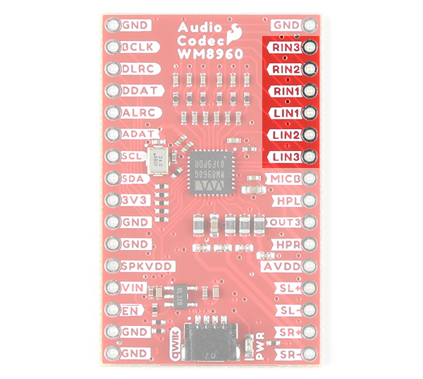
The WM8960 includes 6x flexible analog input pins. These pins can be used for line level or microphone level (balanced or un-balanced). Note that balanced microphones refers to differential microphones while un-balanced microphones refers to single-ended microphones.
Remember the block diagram that was linked earlier just before soldering the headers to the board? The datasheet goes into more detail with the input path for the left and right channel.
Below is a modified image of the block diagram that highlights the input signal path before the left ADC for the left input channels on page 19.
Below is a modified image of the block diagram that highlights the input signal path before the right ADC for the right input channels on page 20.
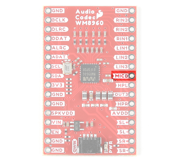
The MICB or MICBIAS provides a low noise reference voltage for biasing eletret condenser microphones (ECMs).
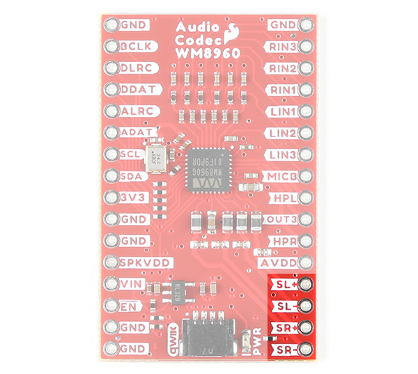
The WM8960 includes differential stereo speaker outputs for the left and right speaker. The speaker is rated as a class D speaker driver and can drive 1W into 8Ω speakers. For users looking to power the speakers with a separate power supply, you can cut the jumper between the pads labeled as SPKVDD and VIN on the back of the board.
The WM8960 can drive 16Ω and 32Ω headphones. The connection will depend on your setup. Make sure to check out the Headphone Output in the datasheet on page 41 for more information.

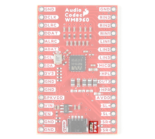
The board includes one LED labeled as PWR. This indicates when there is power on the 3.3V net to power the IC's digital circuit. You can disable it with the jumper on the back of the board.
The following ten jumpers are included on the Audio Codec Breakout - WM8960.
The board dimensions of the Audio Codec Breakout - WM8960 is 1.60" x 1.00".
There are a number of ways to connect to the input and output pins of the WM8960. We will go over each .
Header pins were left off the Audio Codec Breakout to allow users the flexibility of connecting any type of 0.1"-spaced header to the board. Depending on your connections, you may need to solder additional breakout boards and adapters. For temporary connections to the I/O pins, you could use IC hooks to test out the pins. However, you'll need to solder headers or wires of your choice to the board for a secure connection. For the scope of this tutorial, we will be soldering male header pins on the board and wiring the circuit on a breadboard. Here are a few tutorials to connect to the pads depending on your personal preference.
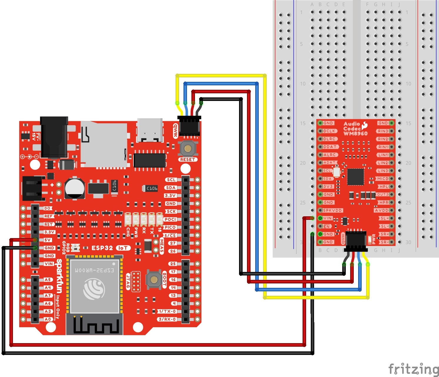
To power the WM8960 appropriately, you will just need to provide power to VIN and the 3V3 pins. As stated in the Hardware Overview: Power, you can take advantage of your development board's voltages without adjusting jumpers. We recommend making the following connection listed in the table.
| Audio Codec - WM8960 | IoT RedBoard - ESP32 |
|---|---|
| VIN | 5V |
| GND | GND (Additional Ground, optional) |
| Qwiic Cable's 3.3V pin (or 3.3V) |
Qwiic Cable's 3.3V pin (or 3.3V) |
| Qwiic Cable's GND pin (or GND) |
Qwiic Cable's GND pin (or GND) |
Using wires and the Qwiic cable to power VIN and 3V3, your circuit should look similar to the circuit diagram below. We will use this method to power the audio codec for the proceeding circuit diagrams.

Depending on your setup, you could provide a separate input voltage to the SPKVDD and VDD. Just make sure to adjust the jumpers on the back as necessary.
To configure the I2S settings or signal path, you will need to connect to the I2C port. Users can save some time wiring this part of the circuit up by adding a Qwiic cable between the audio codec breakout and the IoT RedBoard ESP32. As an alternative, users could also solder to the PTH as well. We recommend making the following connection listed in the table.
| Audio Codec - WM8960 | IoT RedBoard - ESP32 |
|---|---|
| Qwiic Cable's SCL pin (or SCL) |
Qwiic Cable's SCL pin (or SCL) |
| Qwiic Cable's SDA pin (or SDA) |
Qwiic Cable's SDA pin (or SDA) |
| Qwiic Cable's 3.3V pin (or 3.3V) |
Qwiic Cable's 3.3V pin (or 3.3V) |
| Qwiic Cable's GND pin (or GND) |
Qwiic Cable's GND pin (or GND) |
Surprise! Your connection is basically the same as the circuit diagram in the previous section. We just highlighted the circuit connection for I2C data and clock lines here.
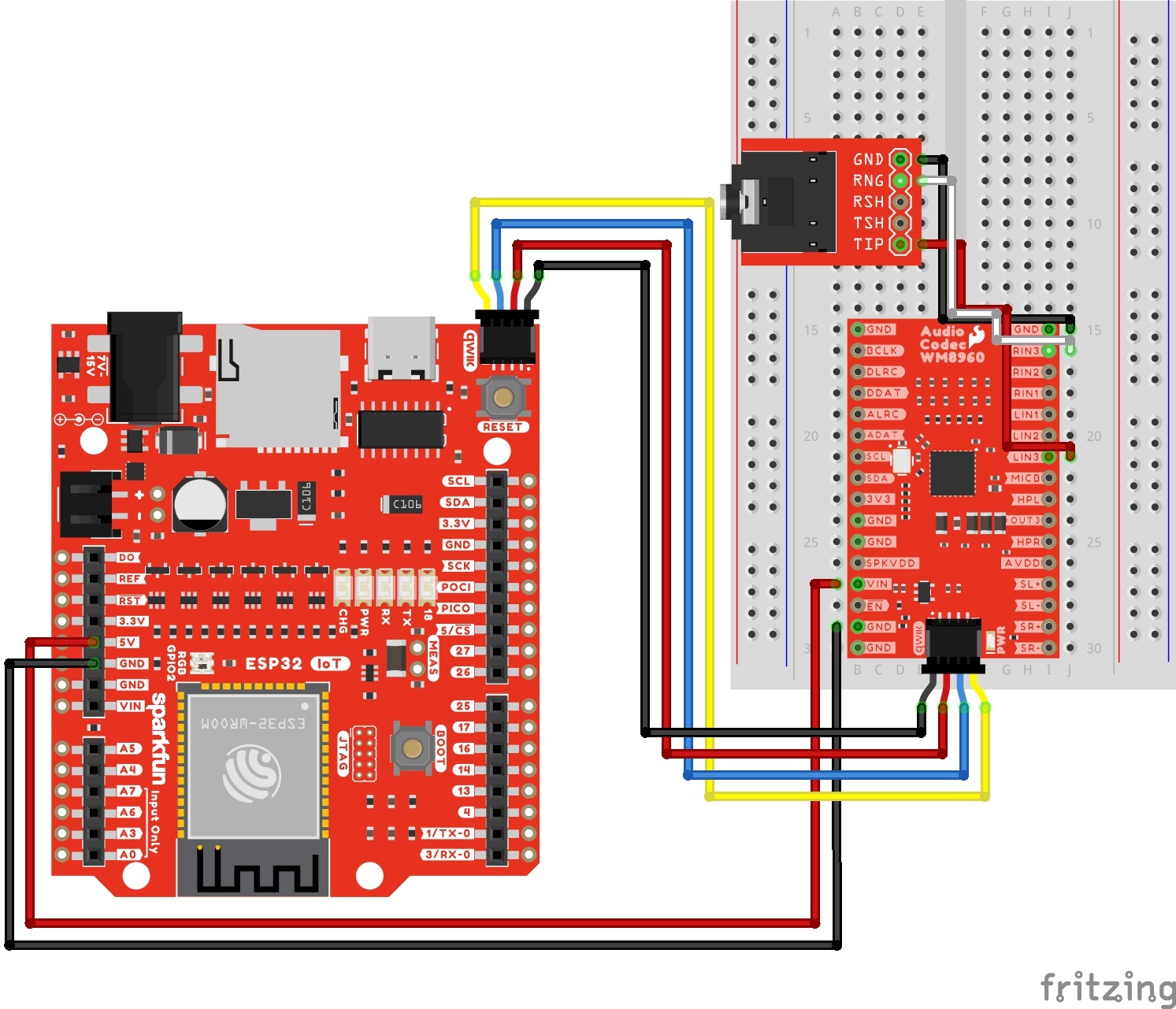
The following connection is for a line level input 3. For simplicity, the table does not include the power and I2C pins.
| Audio Codec - WM8960 | TRS Connector |
|---|---|
| LINPUT3 | Tip |
| RINPUT3 | Ring |
| GND | Sleeve |
Your circuit should look similar to the circuit diagram below.
The following connection is for a line level input 2. For simplicity, the table does not include the power and I2C pins.
| Audio Codec - WM8960 | TRS Connector |
|---|---|
| LINPUT2 | Tip |
| RINPUT2 | Ring |
| GND | Sleeve |
Your circuit should look similar to the circuit diagram below.

The following connection is for a line level input 1. For simplicity, the table does not include the power and I2C pins.
| Audio Codec - WM8960 | TRS Connector |
|---|---|
| LINPUT1 | Tip |
| RINPUT1 | Ring |
| GND | Sleeve |
Your circuit should look similar to the circuit diagram below.

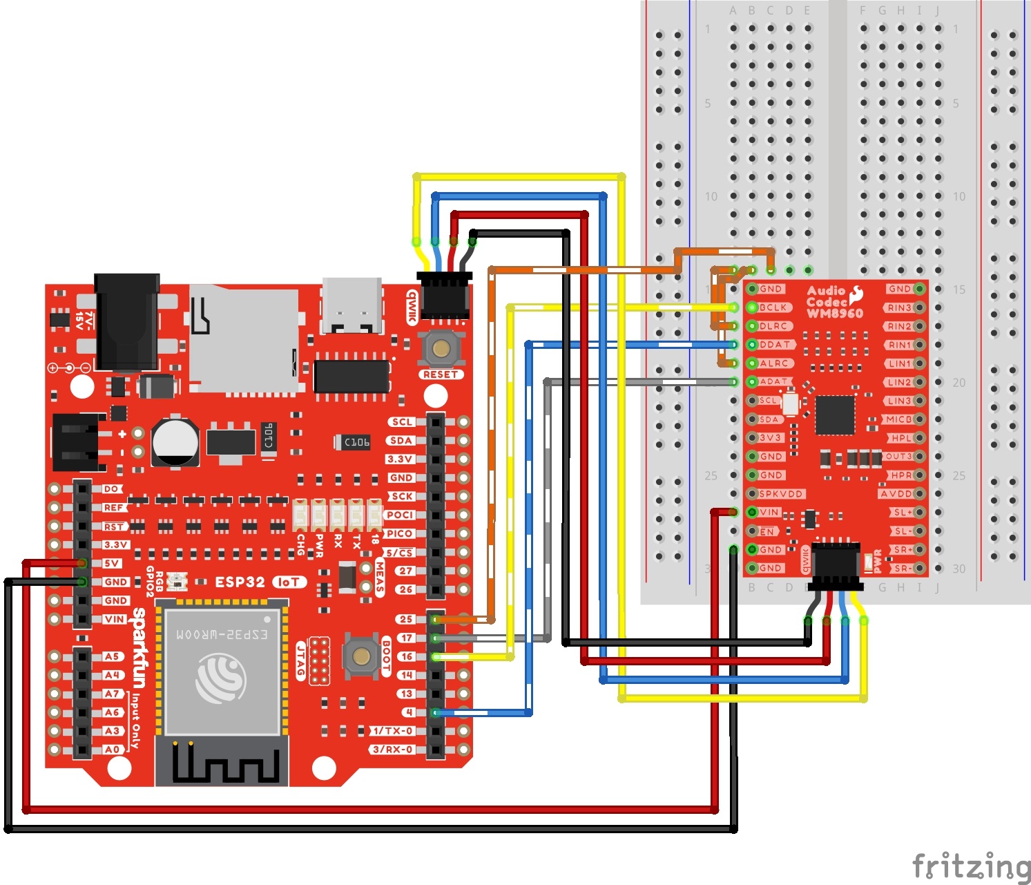
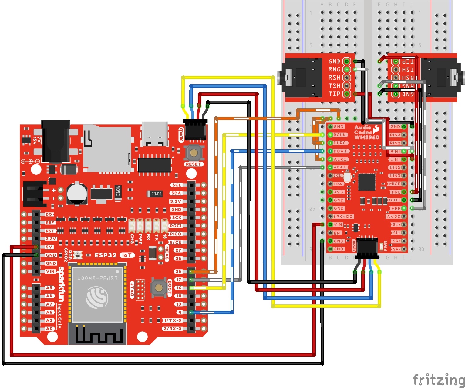
The following connection is for passing an audio source through the ADC and immediately back to the DAC. For simplicity, the table does not include the power and I2C pins. Note that this is for setting the codec as a I2S peripheral.
| Audio Codec - WM8960 | IoT RedBoard - ESP32 |
|---|---|
| DACDAT | 4 |
| BCLK | 16 |
| ADCDAT | 17 |
| DACLRC | 25 |
| ADCLRC | 25 |
Your circuit should look similar to the circuit diagram below.
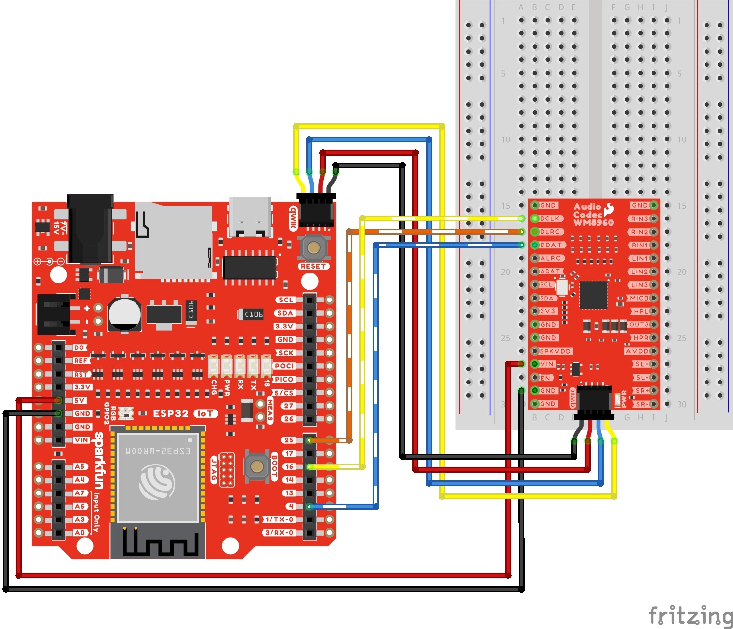
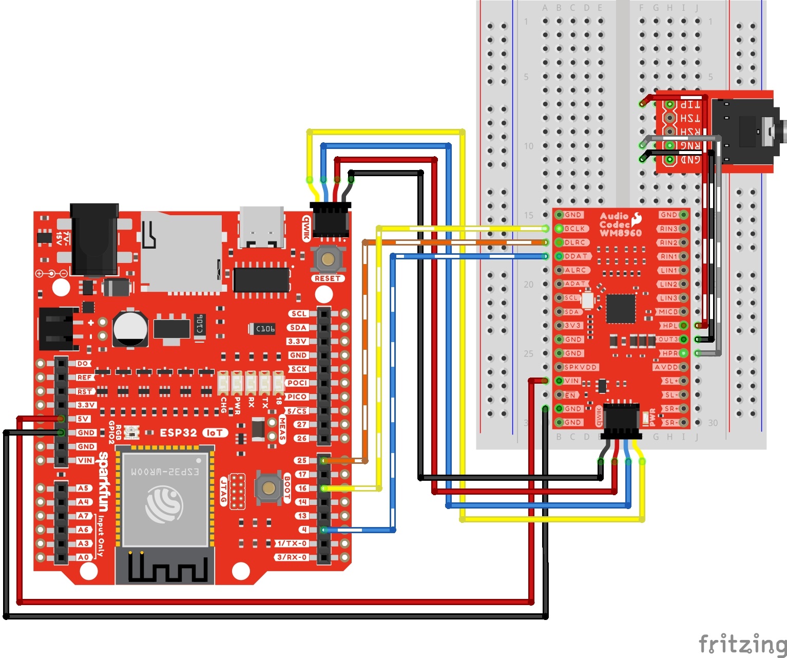
The following connection is for decoding audio. One example is if users connect an audio Bluetooth® device (such as your phone or laptop) to the ESP32 and stream music wirelessly. For simplicity, the table does not include the power and I2C pins. Note that this is for setting the codec as a I2S peripheral.
| Audio Codec - WM8960 | IoT RedBoard - ESP32 |
|---|---|
| DACDAT | 4 |
| BCLK | 16 |
| DACLRC | 25 |
Your circuit should look similar to the circuit diagram below.
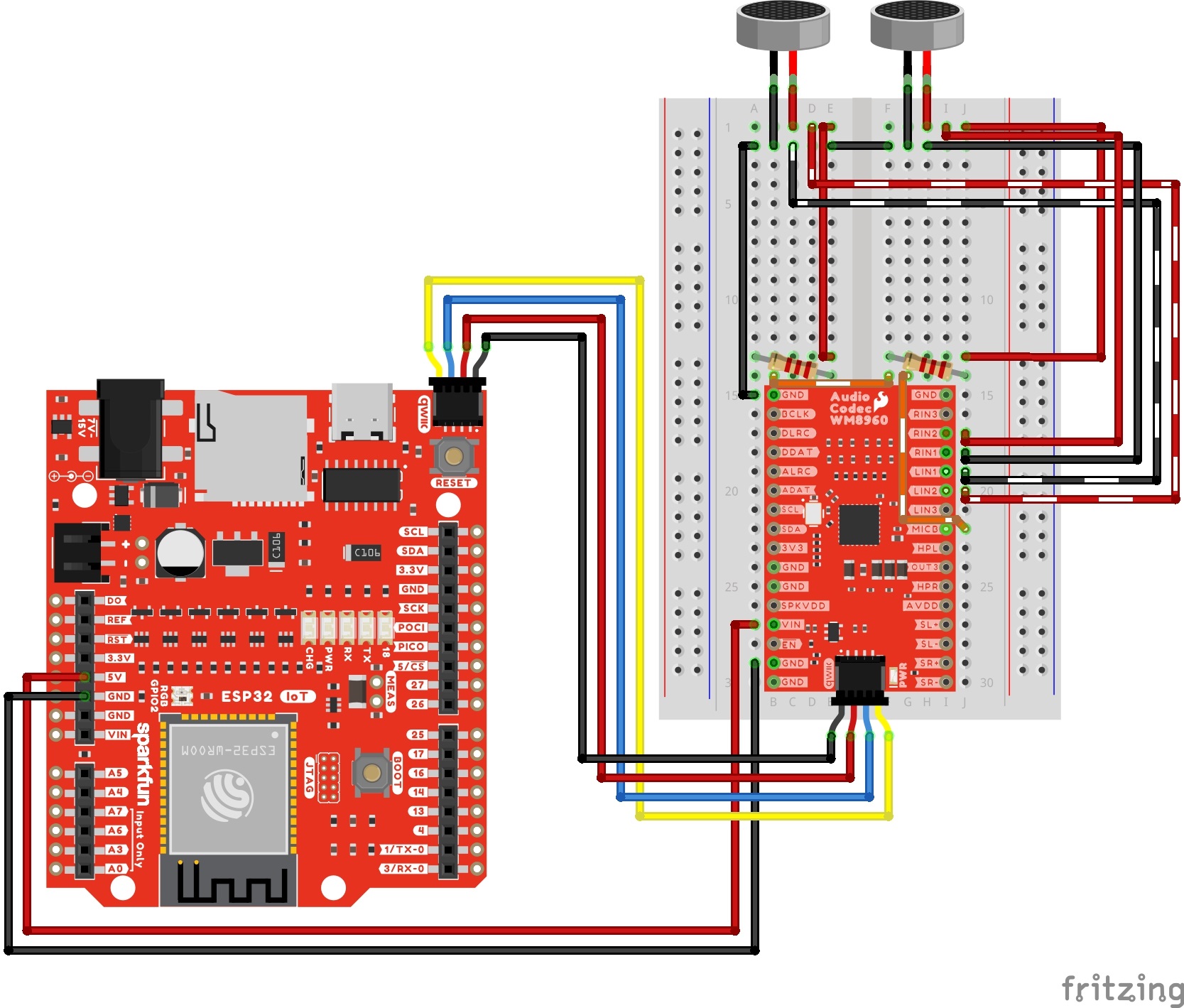
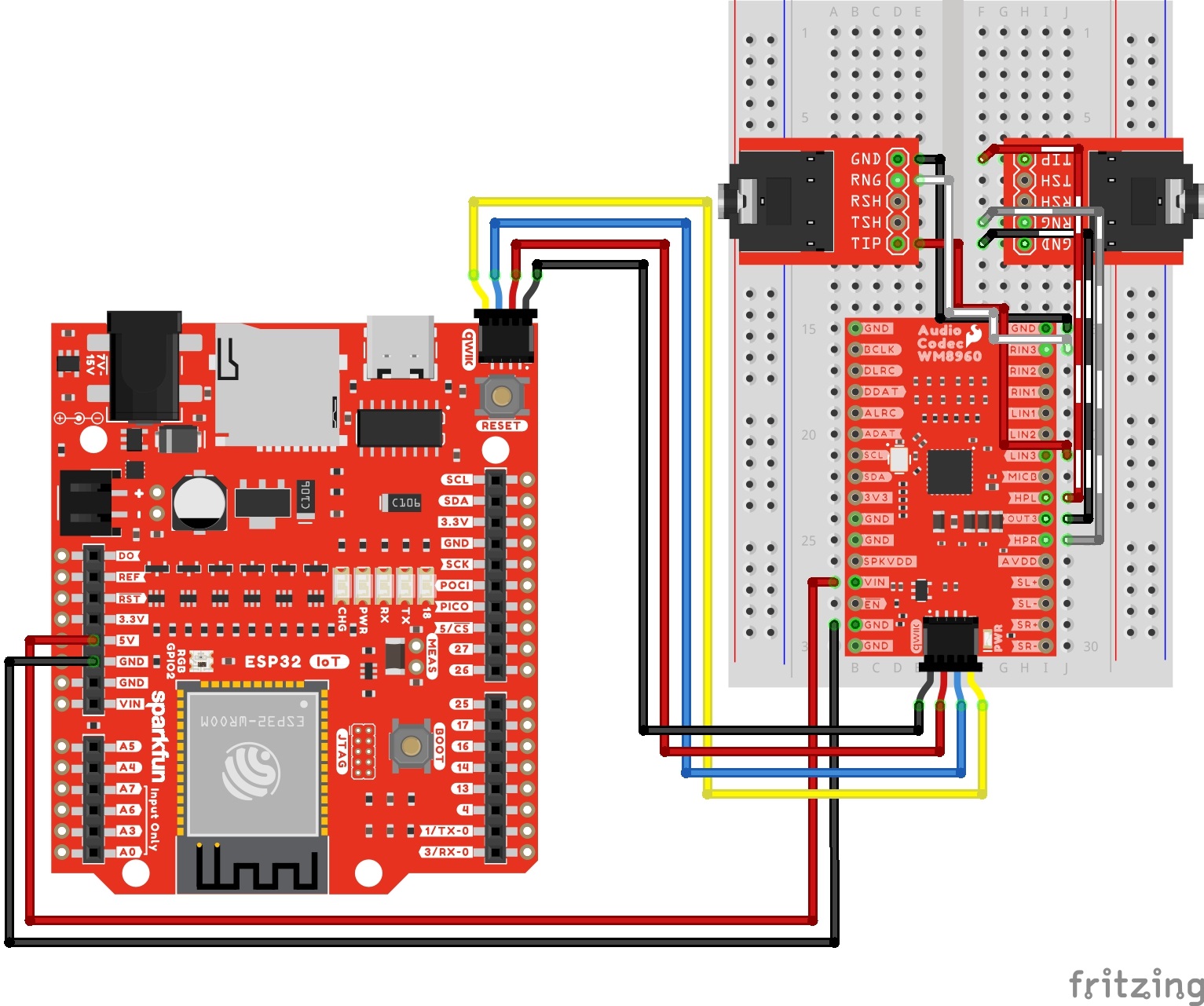
The following connection is for connecting differential microphones to the audio codec. When using a pseudo-differential microphone configuration, make sure to include a 2.2kΩ resistor between the MICBIAS and the + terminals of each differential microphone. You will also need to set voltage on the MICBIAS pin. For simplicity, the table does not include the power and I2C pins.
| Audio Codec - WM8960 | Resistor | Electret Microphone |
|---|---|---|
| GND | Left Mic - | |
| LINPUT1 | Left Mic - | |
| LINPUT2 | Left Mic + | |
| MICBIAS | 2.2kΩ | Right Mic + |
| GND | Right Mic - | |
| LINPUT1 | Right Mic - | |
| LINPUT2 | Right Mic + | |
| MICBIAS | 2.2kΩ | Right Mic + |
Your circuit should look similar to the circuit diagram below.
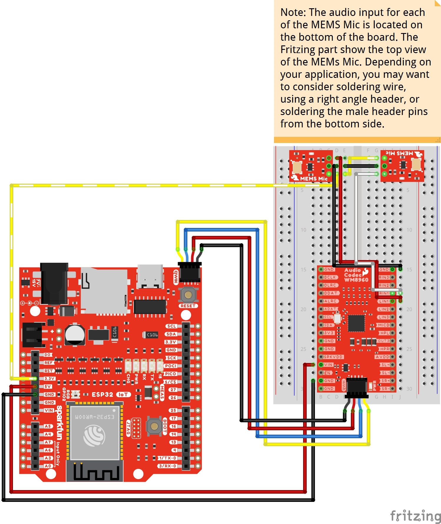
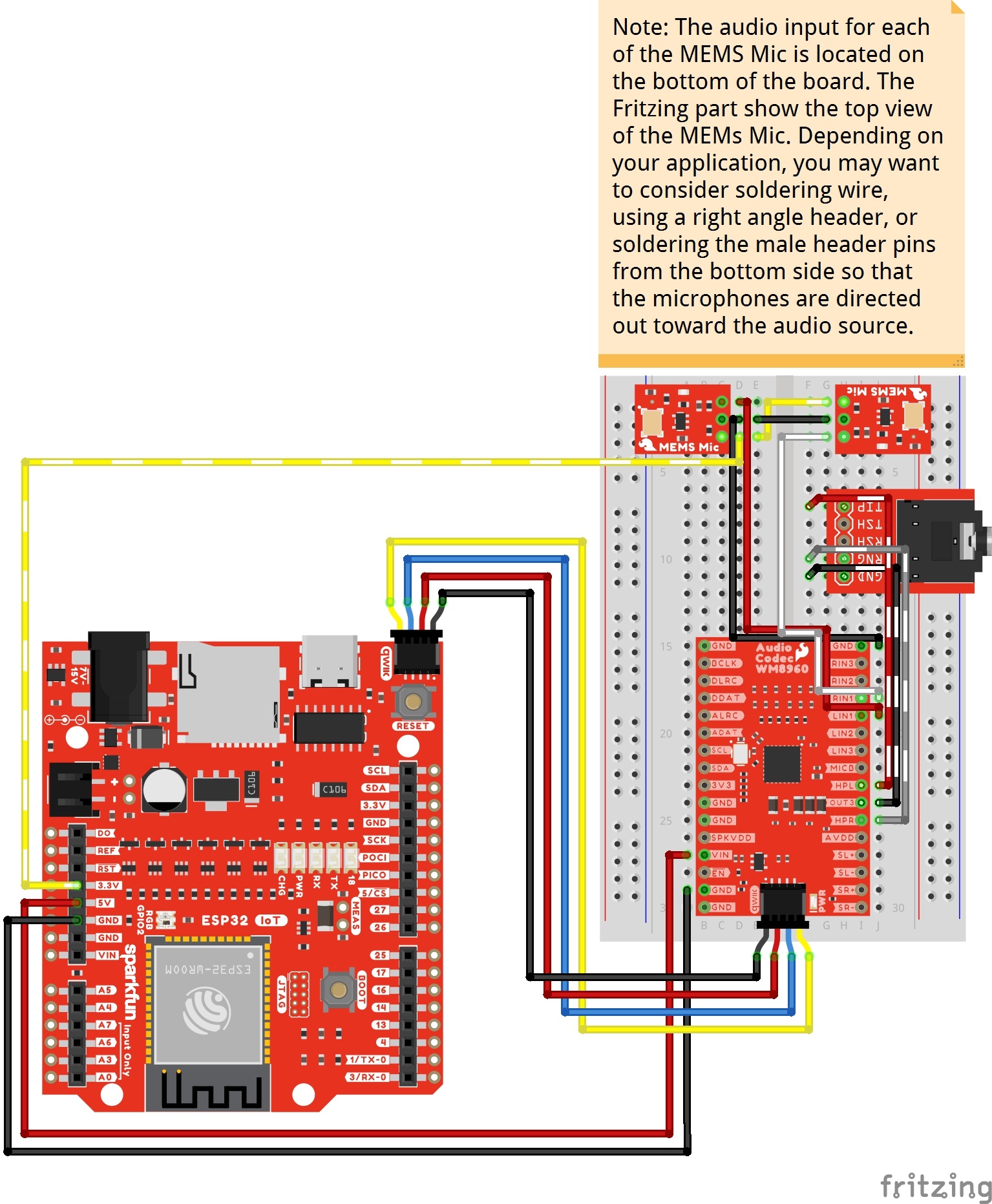
The following connection is for connecting single ended microphones to the audio codec. Instead of using a line level input from the TRS connector, users can also connect unbalanced microphones (these are usually microphones with an amplifier on the breakout boards and have one audio output pin) to the left and right pins of INPUT1. Make sure to also connect power and GND to the boards. For simplicity, the table does not include the power and I2C pins between the ESP32 and WM8960.
| Audio Codec - WM8960 | Single Ended Microphone (Left) | Single Ended Microphone (Right) | IoT RedBoard - ESP32 |
|---|---|---|---|
| Qwiic Cable's GND pin (or GND) |
GND | GND | GND |
| LINPUT1 | AUD | ||
| RINPUT1 | AUD | ||
| Qwiic Cable's 3.3V pin (or 3.3V) |
3.3V | 3.3V | 3.3V |
Your circuit should look similar to the circuit diagram below.
Based on the recommended output configuration from the datasheet, we will be using a capless headphone output in this tutorial.
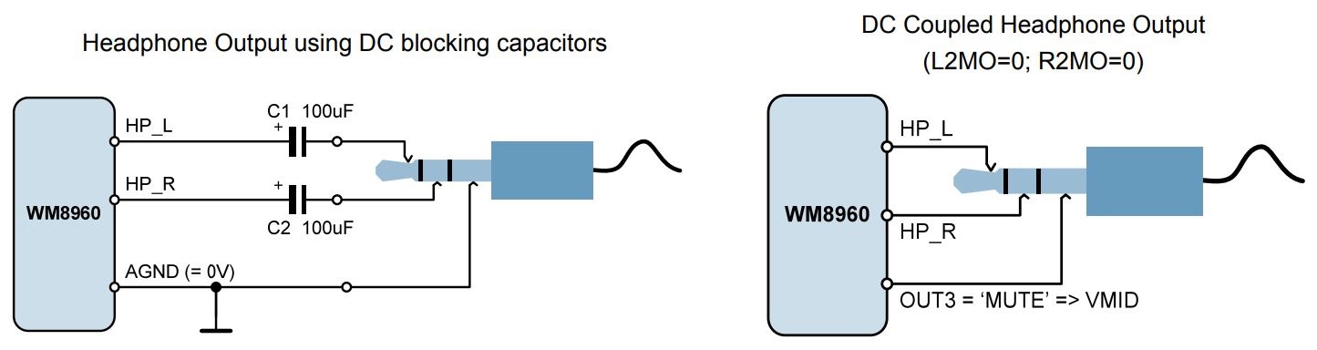
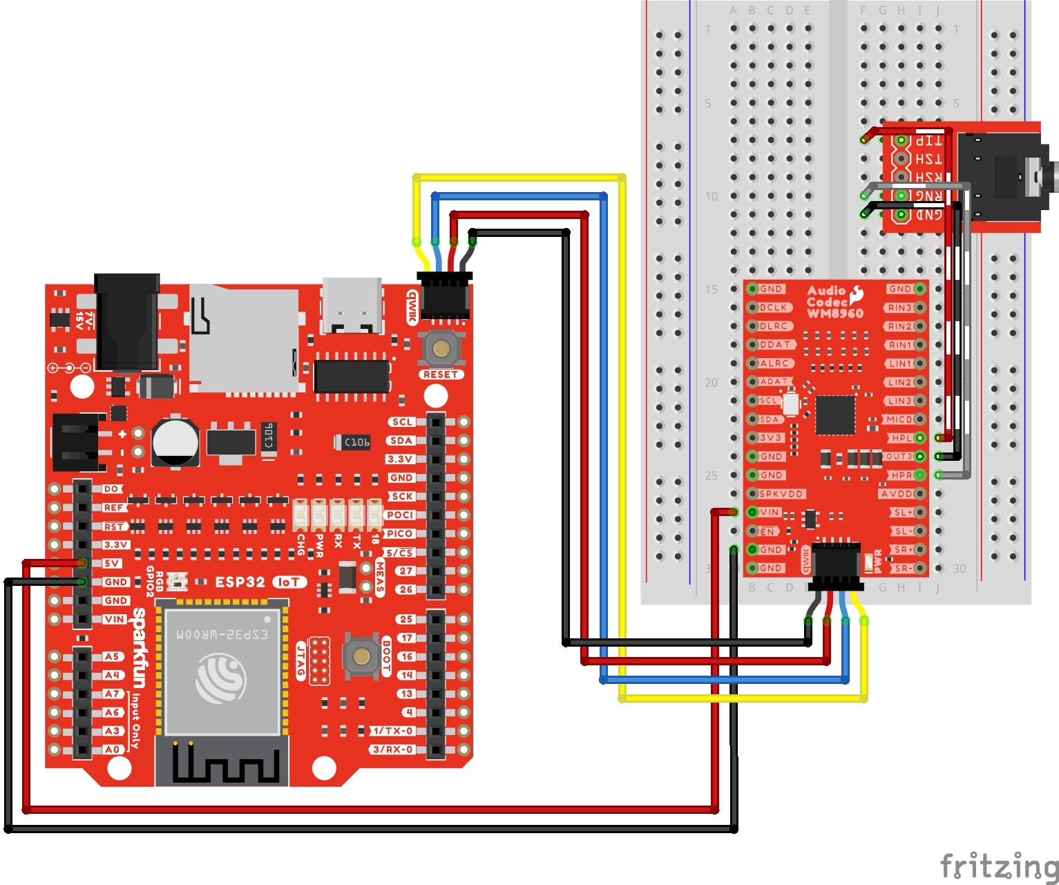
The following connection is for connecting headphones to the audio codec's headphone output. For simplicity, the table does not include the power and I2C pins.
| Audio Codec - WM8960 | TRS Connector |
|---|---|
| HPL | Tip |
| HPR | Ring |
| OUT3 | Sleeve |
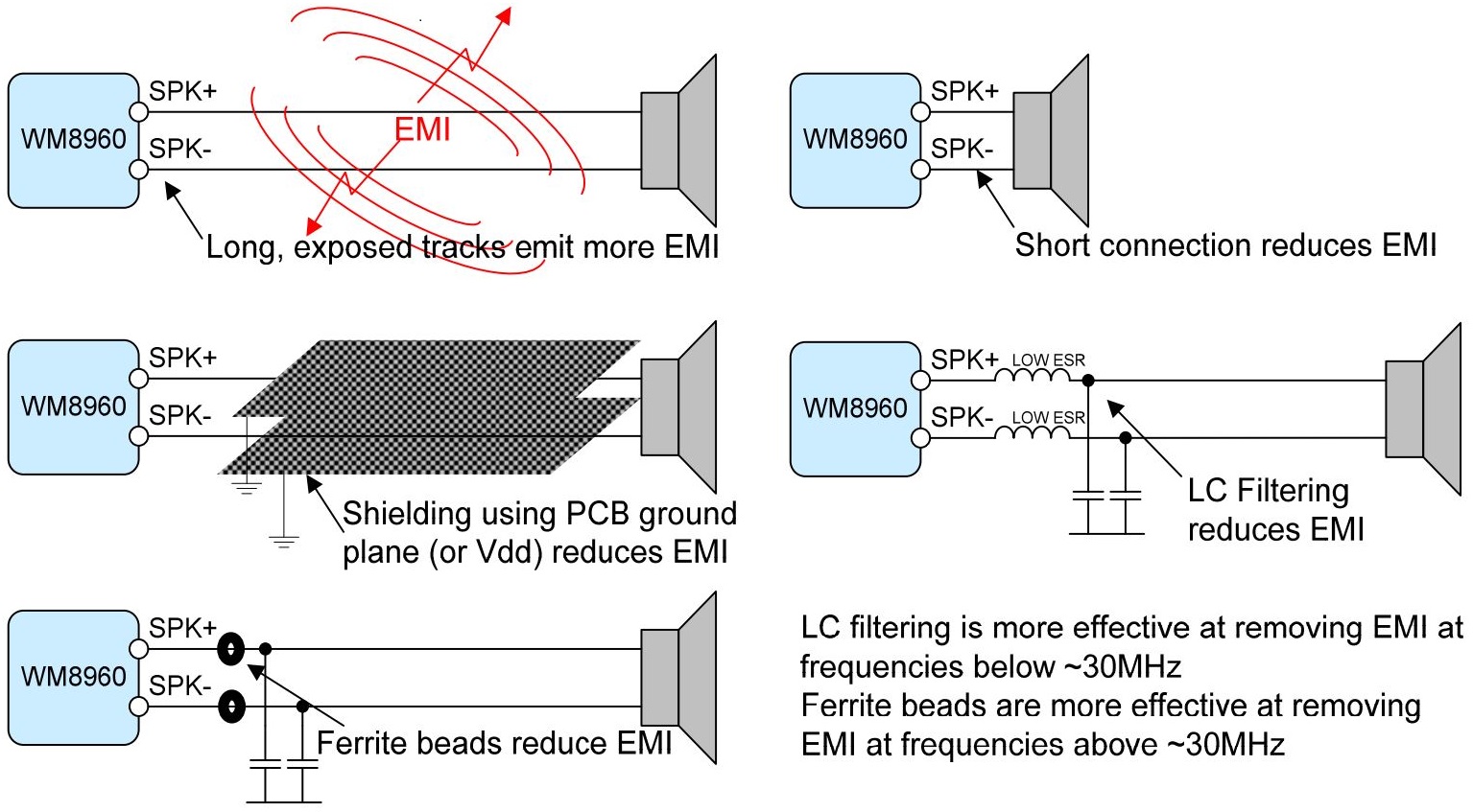
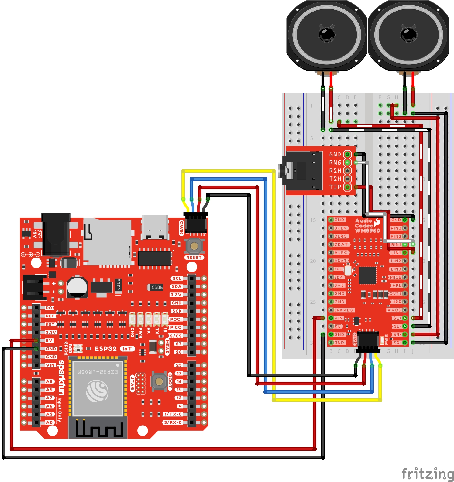
There are a few recommended speaker output configurations from the datasheet to minimize the speaker connection losses due to series resistance and EMI. For a basic setup, we will be using a short wire connection between the audio codec's breakout board and each differential speaker. For those that require long exposed track and want to go the extra mile, users can build an LC filter circuit, add ferrite beads, or shield the wires using PCB ground plane (or Vdd).
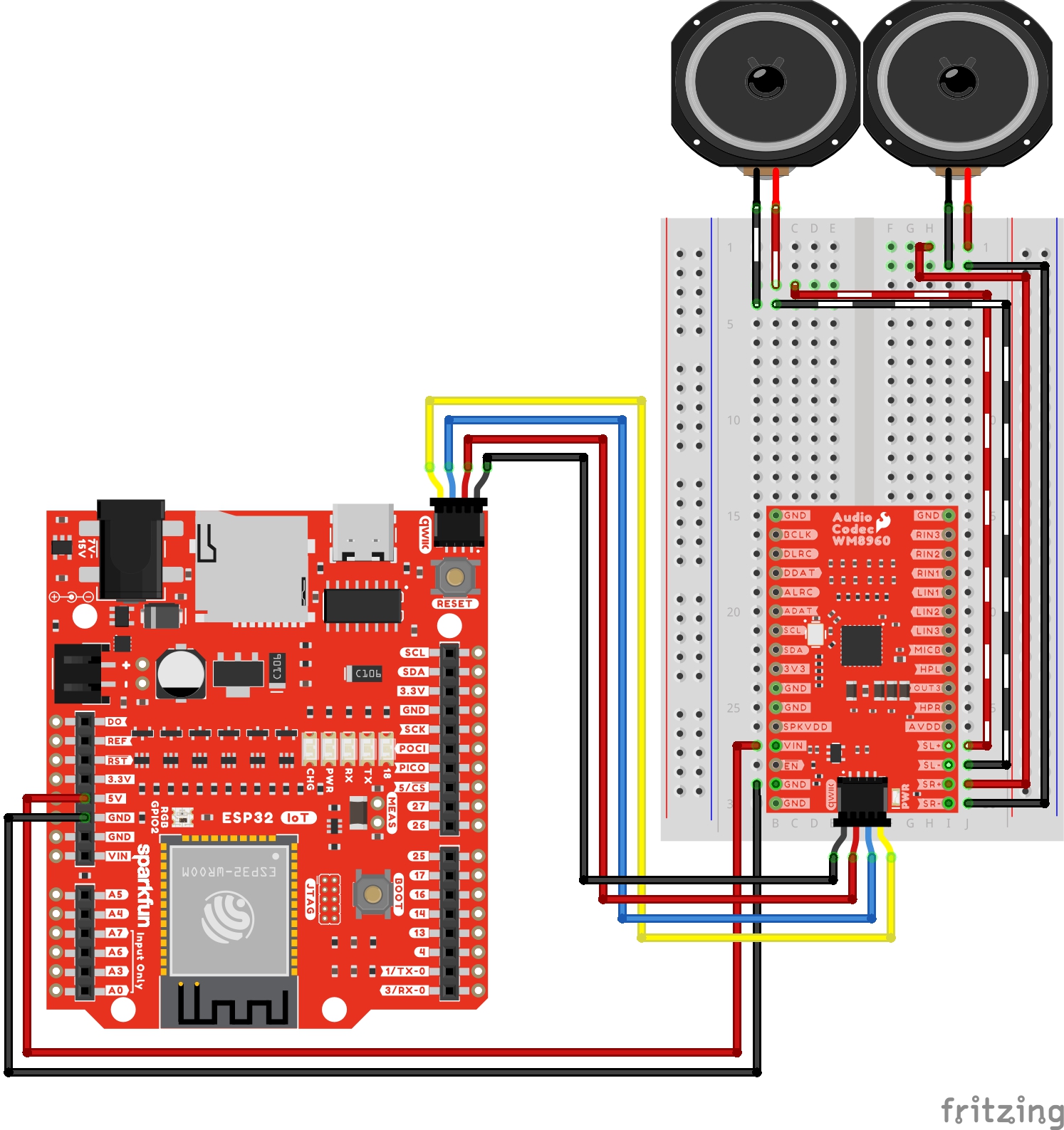
The following connection is for connecting speakers to the audio codec's speaker output channels. For simplicity, the table does not include the power and I2C pins.
| Audio Codec - WM8960 | Speakers |
|---|---|
| SL+ | Speaker Left + |
| SL- | Speaker Left - |
| SR+ | Speaker Right + |
| SR+ | Speaker Right - |
We'll assume that you installed the necessary board files and drivers for your development board. In this case, we used the IoT RedBoard - ESP32 which uses the CH340 USB-to-serial converter. If you are using a Processor Board, make sure to check out its hookup guide for your Processor Board.
The SparkFun Arduino library can be downloaded with the Arduino library manager by searching 'SparkFun Audio Codec Breakout WM8960' or you can grab the zip here from the GitHub repository to manually install.
In this example, we will pass a line level audio source into the WM8960's line input 3 port. The signal will go through the mixers and gain stages of the audio codec. For this output, we will be sending the audio to the headphones.
Connect power, I2C, line input 3 port, and the headphone output as explained earlier. Your circuit should look similar to the circuit diagram below.
Connect a USB cable into your IoT RedBoard ESP32 and a TRS cable from your audio source (e.g. MP3 player, smartphone, or computer) into the audio connector. Then connect your headphones to the output. For those that are sensitive to sounds, you may want to hear the example output before inserting the headphones into your ears.
From the menu, select the following: File > Examples > SparkFun WM8960 Arduino Library > Example_01_Volume. If you have not already, select your Board (in this case the SparkFun ESP32 IoT RedBoard), and associated COM port. Then hit the upload button.
Open the Arduino Serial Monitor and set it to 115200 baud to view the serial output. Then hit the play button on your audio source. Make sure that the volume from the audio source is turned up. You should hear some music from the headphones. After every 5 seconds, the volume will decrease until it is muted.
If you waited too long to hit the play button, the audio codec may have already muted the track. Try hitting the reset button on the IoT RedBoard to restart the example since it executes the code once.
In this example, we will pass a line level audio source into the WM8960's line input 2 port. The signal will go through the mixers and gain stages of the audio codec like the previous example. For the output we will be sending the audio to the headphones as well.
Connect power, I2C, line input 2 port, and the headphone output as explained earlier. Your circuit should look similar to the circuit diagram below.

If you have not already, insert a USB cable into your IoT RedBoard ESP32 and a TRS cable from your audio source (e.g. MP3 player, smartphone, or computer) into the audio connector. Then connect your headphones to the output. For those that are sensitive to sounds, you may want to hear the example output before inserting the headphones into your ears.
From the menu, select the following: File > Examples > SparkFun WM8960 Arduino Library > Example_02_INPUT2. If you have not already, select your Board (in this case the SparkFun ESP32 IoT RedBoard), and associated COM port. Then hit the upload button.
Open the Arduino Serial Monitor and set it to 115200 baud to view the serial output. Then hit the play button on your audio source. Make sure that the volume from the audio source is turned up. You should hear some music from the headphones. Compared to the first example, this just sets the volume once.
Similar to the past two examples, we will pass the line level audio source into the WM8960's line input 1 port. As an alternative, users can also wire up single ended microphones to input 1 instead of using a line level audio source from the TRS connector. The signal will go through the mixers and gain stages of the audio codec. Again, we will be sending the audio to the headphone output.
Connect power, I2C, line input 1, and the headphone output as explained earlier. Your circuit should look similar to the circuit diagram below.

Connect a USB cable into your IoT RedBoard ESP32 and a TRS cable from your audio source (e.g. MP3 player, smartphone, or computer) into the audio connector. Then connect your headphones to the output. For those that are sensitive to sounds, you may want to hear the example output before inserting the headphones into your ears.
Input 1 also has the ability to allow single ended microphones to the left and right inputs. As an alternative, you can also connect single ended electret or MEMS microphones to these pins. Connect power, I2C, single ended microphones, and the headphone output as explained earlier. Your circuit should look similar to the circuit diagram below.
Connect a USB cable into your IoT RedBoard ESP32. Then connect your headphones to the output. For those that are sensitive to sounds, you may want to hear the example output before inserting the headphones into your ears.
From the menu, select the following: File > Examples > SparkFun WM8960 Arduino Library > Example_03_INPUT1. If you have not already, select your Board (in this case the SparkFun ESP32 IoT RedBoard), and associated COM port. Then hit the upload button.
Open the Arduino Serial Monitor and set it to 115200 baud to view the serial output. Then hit the play button on your audio source if you are using a TRS connector. Make sure that the volume from the audio source is turned up. You should hear some music from the headphones. This is basically the same as the previous two examples but now we are using input 1.
In this example, we will pass a line level audio source into the WM8960's line input 1 port. The signal will go through the mixers and gain stages of the audio codec. For the output, we will be sending the audio to a pair of differential speakers.
Connect power, I2C, line input 1, and the speakers on the output channels as explained earlier. Your circuit should look similar to the circuit diagram below.
If you have not already, insert a USB cable into your IoT RedBoard ESP32 and a TRS cable from your audio source (e.g. MP3 player, smartphone, or computer) into the audio connector.
From the menu, select the following: File > Examples > SparkFun WM8960 Arduino Library > Example_04_Speaker. If you have not already, select your Board (in this case the SparkFun ESP32 IoT RedBoard), and associated COM port. Then hit the upload button.
Open the Arduino Serial Monitor and set it to 115200 baud to view the serial output. Then hit the play button on your audio source. Make sure that the volume from the audio source is turned up. You should hear some music from the speakers.
In this example, we will pass a line level audio source into the WM8960's line input 1 port. The signal will go through the mixers and gain stages of the audio codec. What's different in this example is that we will also turn on loopback so that the ADC is fed directly to the DAC. The output of the DAC will then be sent to the headphone output.
Connect power, I2C, line input 1, and the headphone output as explained earlier. Your circuit should look similar to the circuit diagram below.
If you have not already, insert a USB cable into your IoT RedBoard ESP32 and a TRS cable from your audio source (e.g. MP3 player, smartphone, or computer) into the audio connector. Then connect your headphones to the output. For those that are sensitive to sounds, you may want to hear the example output before inserting the headphones into your ears.
From the menu, select the following: File > Examples > SparkFun WM8960 Arduino Library > Example_05_Loopback. If you have not already, select your Board (in this case the SparkFun ESP32 IoT RedBoard), and associated COM port. Then hit the upload button.
Open the Arduino Serial Monitor and set it to 115200 baud to view the serial output. Then hit the play button on your audio source. Make sure that the volume from the audio source is turned up. You should hear some music from the headphones.
In this example, we will pass a line level audio source into the WM8960's line input 1 port. The audio source will go through the mixers and gain stages into the ADC. With the loopback turned on, the ADC is sent directly to the DAC and output to the headphone output. In the loop() function, turn on and off the 3D enhance feature every 5 seconds.
Connect power, I2C, line input 1, and the headphone output as explained earlier. Your circuit should look similar to the circuit diagram below.
Connect a USB cable into your IoT RedBoard ESP32 and a TRS cable from your audio source (e.g. MP3 player, smartphone, or computer) into the audio connector. Then connect your headphones to the output. For those that are sensitive to sounds, you may want to hear the example output before inserting the headphones into your ears.
From the menu, select the following: File > Examples > SparkFun WM8960 Arduino Library > Example_06_3D_Enhance. If you have not already, select your Board (in this case the SparkFun ESP32 IoT RedBoard), and associated COM port. Then hit the upload button.
Open the Arduino Serial Monitor and set it to 115200 baud to view the serial output when the 3D enhance mode is enabled. Then hit the play button on your audio source. Make sure that the volume from the audio source is turned up. Experience the virtual surround sound!
in this example, we will set the microphone bias voltage and measure the voltage. This is for advanced users looking to add a differential microphone to the microphone input pins.
Connect power and I2C. as explained earlier. Then grab a multimeter with alligator clips and M/M jumper wires. Connect the wires to MICBIAS and GND to measure the voltage. Your circuit should look similar to the circuit diagram below.
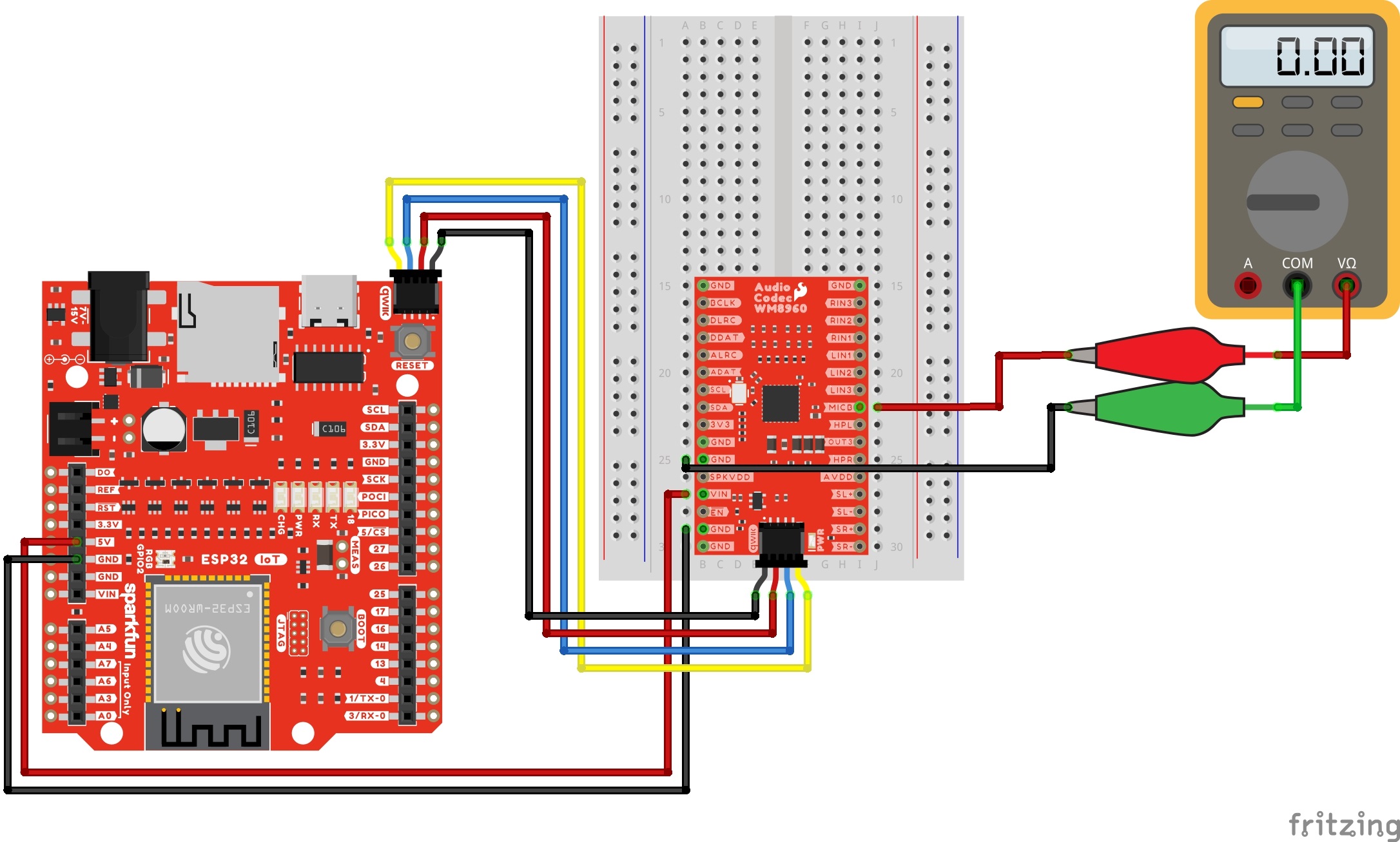
If you have not already, insert a USB cable into your IoT RedBoard ESP32.
From the menu, select the following: File > Examples > SparkFun WM8960 Arduino Library > Example_07_MicBias. If you have not already, select your Board (in this case the SparkFun ESP32 IoT RedBoard), and associated COM port. Then hit the upload button.
Open the Arduino Serial Monitor and set it to 115200 baud to view the serial output. Measuring the output with a multimeter, the voltage should be similar to the voltages that were set for the MICBIAS pin. After 3 seconds, the pin will be disabled. If you missed the window to measure the MICBIAS voltage, hit the reset button the IoT RedBoard to run the example again.
If you are satisfied with your MICBIAS voltage, head over to example 14 to add a resistor in series with each electret microphone.
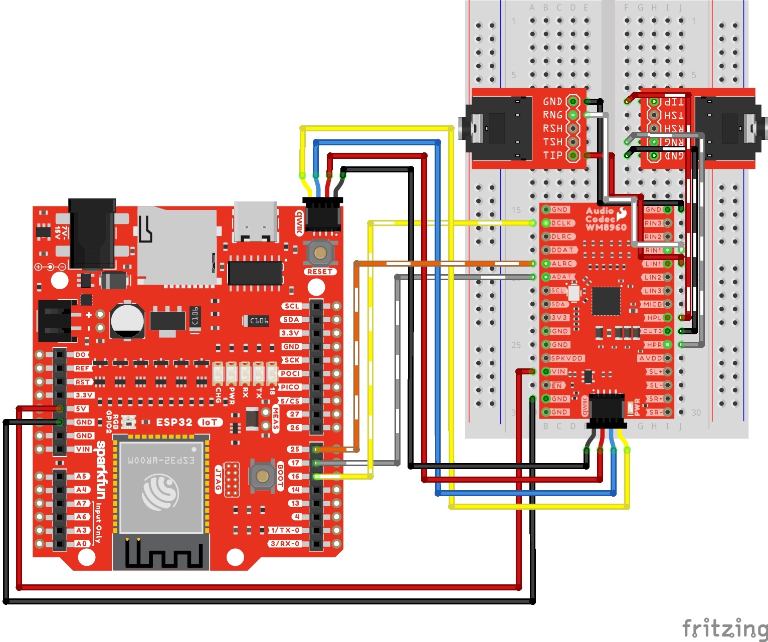
In this example, we will pass a line level audio source into the WM8960's line input 1 port. The signal will go through the mixers and gain stages of the codec. The audio will be read from the ADC via I2S and then immediately sent back to the DAC via I2S. The output of the DAC will then be sent to the headphone output.
Connect power, I2C, line input 3, and the headphone output as explained earlier. Your circuit should look similar to the circuit diagram below.
Connect a USB cable into your IoT RedBoard ESP32 and a TRS cable from your audio source (e.g. MP3 player, smartphone, or computer) into the audio connector. Then connect your headphones to the output. For those that are sensitive to sounds, you may want to hear the example output before inserting the headphones into your ears.
From the menu, select the following: File > Examples > SparkFun WM8960 Arduino Library > Example_08_I2S_Passthrough. If you have not already, select your Board (in this case the SparkFun ESP32 IoT RedBoard), and associated COM port. Then hit the upload button.
Open the Arduino Serial Monitor and set it to 115200 baud to view the serial output. Then hit the play button on your audio source. Make sure that the volume from the audio source is turned up. You should hear some music from the headphones.
In this example, we will wirelessly connect a Bluetooth audio source and use the IoT RedBoard ESP32 as a Bluetooth audio sink. Once the audio codec is set as an I2S peripherial, the ESP32 will receive audio and play it back via I2S. Once the WM8960 receives the I2S audio, it will be sent to the DAC and then the headphone output.
Connect power, I2C, I2S, and the headphone output as explained earlier. Your circuit should look similar to the circuit diagram below.
Connect a USB cable into your IoT RedBoard ESP32. Turn on the Bluetooth on your audio source (e.g. MP3 player, smartphone, or computer). Then connect your headphones to the output. For those that are sensitive to sounds, you may want to hear the example output before inserting the headphones into your ears.
From the menu, select the following: File > Examples > SparkFun WM8960 Arduino Library > Example_09_I2S_Bluetooth. If you have not already, select your Board (in this case the SparkFun ESP32 IoT RedBoard), and associated COM port. Then hit the upload button.
Open the Arduino Serial Monitor and set it to 1152000 baud to view the serial output. On your phone, pair and connect to the ESP32's Bluetooth. In this case, the name of the ESP32's Bluetooth is called "myCodec". Then hit the play button on your audio source. Make sure that the volume from the audio source is turned up. You should hear some music from the headphones.
Try adding a battery to the mix to untether the circuit from your computer. Do a little dance or flip and rock to the beat of the music! Of course, you'll want to be careful of the wires while moving around. For a more secure connection, you could take a solderable breadboard or an Arduino shield and manually wire the circuit together
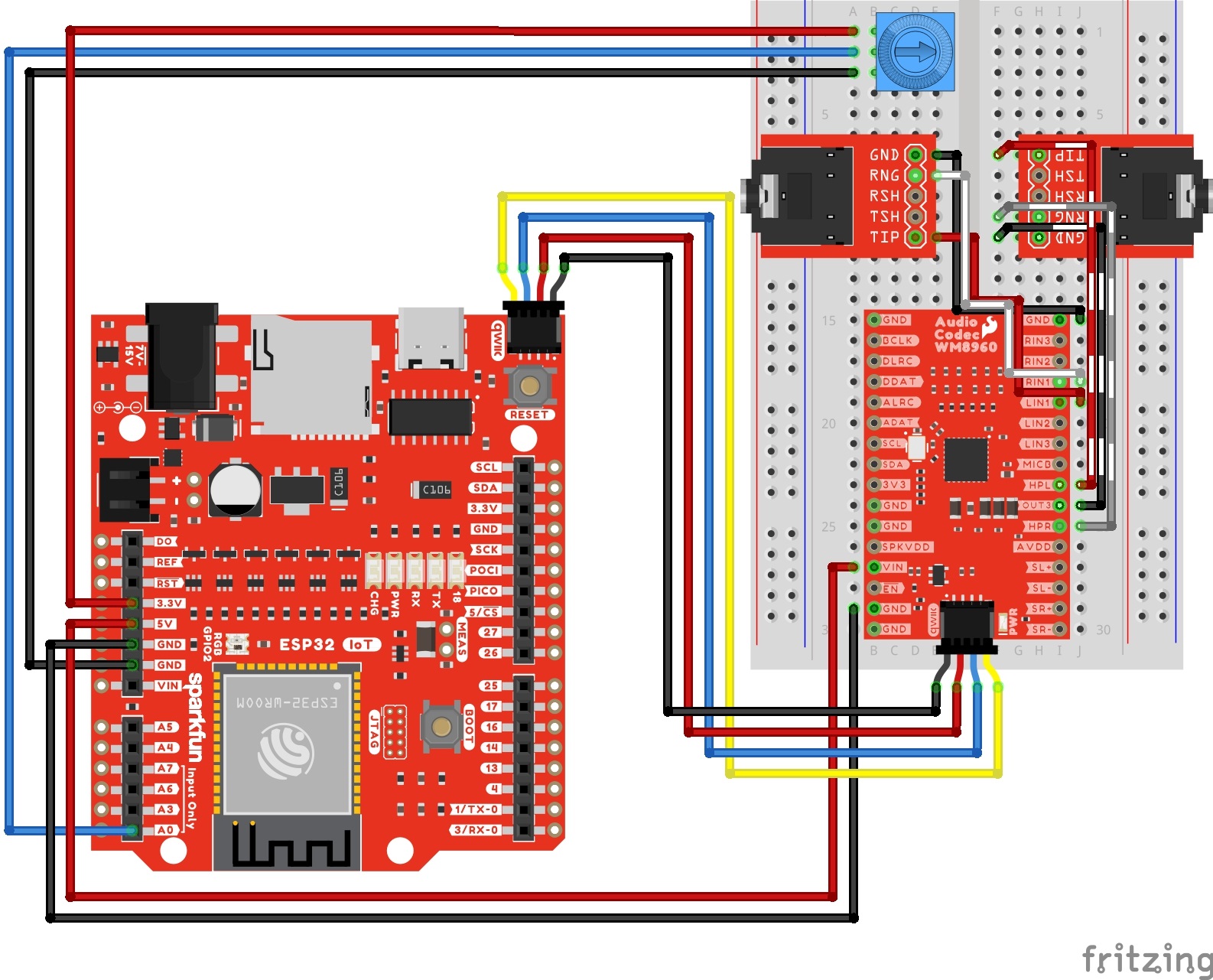
This example is pretty much example 5. The difference is that we are adding a trim pot to the ESP32's analog input and using the measurement to adjust the codec's ADC digital volume.
Connect power, I2C, line input 1, trim pot, and the headphone output. Your circuit should look similar to the circuit diagram below.
If you have not already, insert a USB cable into your IoT RedBoard ESP32 and a TRS cable from your audio source (e.g. MP3 player, smartphone, or computer) into the audio connector. Then connect your headphones to the output. For those that are sensitive to sounds, you may want to hear the example output before inserting the headphones into your ears.
From the menu, select the following: File > Examples > SparkFun WM8960 Arduino Library > Example_10_AdcGain. If you have not already, select your Board (in this case the SparkFun ESP32 IoT RedBoard), and associated COM port. Then hit the upload button.
Open the Arduino Serial Monitor and set it to 115200 baud to view the serial output. Then hit the play button on your audio source. Make sure that the volume from the audio source is turned up. You should hear some music from the headphones. Adjust the volume to your desired setting by rotating the trim pot clockwise or counterclockwise.
This example is similar to example 3. However, we will be connecting to reading I2S audio from the ADC and plotting the audio samples on the Arduino Serial Plotter.
Connect power, I2C, I2S, line input 1, and the headphone output. Your circuit should look similar to the circuit diagram below.
If you have not already, insert a USB cable into your IoT RedBoard ESP32 and a TRS cable from your audio source (e.g. MP3 player, smartphone, or computer) into the audio connector. Then connect your headphones to the output. For those that are sensitive to sounds, you may want to hear the example output before inserting the headphones into your ears.
From the menu, select the following: File > Examples > SparkFun WM8960 Arduino Library > Example_11_VolumePlotter. If you have not already, select your Board (in this case the SparkFun ESP32 IoT RedBoard), and associated COM port. Then hit the upload button.
Open the Arduino Serial Plotter and set it to 115200 baud to view the output. Then hit the play button on your audio source. Make sure that the volume from the audio source is turned up. You should hear some music from the headphones and view the audio samples on the Serial Plotter.
This example builds off of example 5. The difference is that we are adding a trim pot toe the ESP32's analog input and using the measurement to configures the Automatic Level Control (ALC) target value. The ALC will adjust the gain of the PGA input buffer to try and keep the signal level at the target.
Connect power, I2C, line input 1, trim pot, and the headphone output as explained earlier. Your circuit should look similar to the circuit diagram below.
If you have not already, insert a USB cable into your IoT RedBoard ESP32 and a TRS cable from your audio source (e.g. MP3 player, smartphone, or computer) into the audio connector. Then connect your headphones to the output. For those that are sensitive to sounds, you may want to hear the example output before inserting the headphones into your ears.
From the menu, select the following: File > Examples > SparkFun WM8960 Arduino Library > Example_12_AutomaticLevelControl. If you have not already, select your Board (in this case the SparkFun ESP32 IoT RedBoard), and associated COM port. Then hit the upload button.
Open the Arduino Serial Monitor and set it to 115200 baud to view the serial output. Then hit the play button on your audio source. Make sure that the volume from the audio source is turned up. You should hear some music from the headphones.
This example is similar to example 10. The difference is that we are adding a trim pot to the ESP32's analog input and using the measurement to adjust the codec's DAC digital volume.
Connect power, I2C, I2S, line input 1, trim pot, and the headphone output. Your circuit should look similar to the circuit diagram below.
If you have not already, insert a USB cable into your IoT RedBoard ESP32 and a TRS cable from your audio source (e.g. MP3 player, smartphone, or computer) into the audio connector. Then connect your headphones to the output. For those that are sensitive to sounds, you may want to hear the example output before inserting the headphones into your ears.
From the menu, select the following: File > Examples > SparkFun WM8960 Arduino Library > Example_13_DacGain. If you have not already, select your Board (in this case the SparkFun ESP32 IoT RedBoard), and associated COM port. Then hit the upload button.
Open the Arduino Serial Monitor and set it to 115200 baud to view the serial output. Then hit the play button on your audio source. Make sure that the volume from the audio source is turned up. You should hear some music from the headphones. Adjust the volume to your desired setting by rotating the trim pot clockwise or counterclockwise.
Continuing on from example 7, we will use differential microphones as the audio input based on the "pseudo-differential MIC configuration." The example will configure the PGA before passing it to the mixers and gain stages of the codec like the previous examples. The output will be to the headphones.
Connect power, I2C, I2S, differential microphones (each with a 2.2kΩ resistor wired in series with the MICBIAS pin), and the headphone output. Your circuit should look similar to the circuit diagram below.
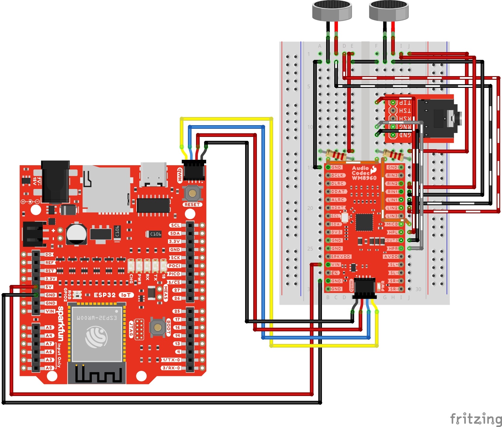
If you have not already, insert a USB cable into your IoT RedBoard ESP32. Then connect your headphones to the output. For those that are sensitive to sounds, you may want to hear the example output before inserting the headphones into your ears.
From the menu, select the following: File > Examples > SparkFun WM8960 Arduino Library > Example_14_Electret_Mics. If you have not already, select your Board (in this case the SparkFun ESP32 IoT RedBoard), and associated COM port. Then hit the upload button.
Open the Arduino Serial Monitor and set it to 115200 baud to view the serial output. Make some noise on the differential microphones. You should hear some audio from the headphones.
Now that you've successfully got your Audio Codec Breakout up and running, it's time to incorporate it into your own project! For more information, check out the resources below:
Looking for more inspiration? Check out these other tutorials related to audio.
learn.sparkfun.com | CC BY-SA 3.0 | SparkFun Electronics | Niwot, Colorado