Proto Pedal Chassis Hookup Guide
 Byron J.,
  MTaylor
Introduction
The Proto Pedal chassis comes with the holes required to interface the PCB, but since different pedal designs use different types of controls, we've left drilling holes for the controls to the builder. This guide will take you through laying out and drilling holes, then painting the chassis.
We'll be drilling a chassis to match the digital Proto Pedal example, which shows an application using a Teensy 3.2 and an Audio Adapter with the Proto Pedal and Proto Pedal Chassis.
Materials
Required:
- The Proto Pedal and Chassis
- A twist drill bit (not spade) that matches the desired hole diameter
- A pilot drill of about 1/8 inch. Make sure it's sharp and fresh!
- A few drill bits between to step up to the desired size.
- Ruler
- Center punch (a large metal screw and hammer will work)
- Variable speed hand drill, wired or cordless
- Clamps, vice, holders
- Some scrap wood blocks
- A pencil
Also Recommended:
- Thin circular file (needle or chain sharpening file)
- Speed square
- Combination square / scribe
- Spring loaded center punch
- Isopropyl Alcohol / Acetone
- Paint
Recommended Reading
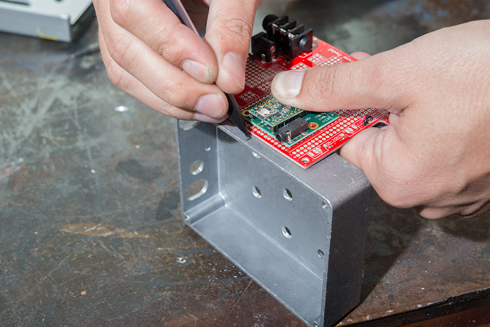
- If got here from the ether, check out the Proto Pedal Assembly and Theory guide which shows how to assemble the circuit board that goes in the case. Make sure to assemble this first.
Laying Out The Holes
Before drilling, we need to figure out where to locate the holes.
This is an exercise in three-dimensional thinking. We need to account for the location of the controls on the panel, as well as the clearance above and below. Above the surface of the pedal, you'll probably want to leave some room around the controls, so you can grab them. Inside the chassis, you need to consider where the internal portion of the control will be located, especially in relation to the taller components on the PCB.
Rough Layout
In this example, we wanted to put five potentiometers on the chassis. We simply moved the knobs around on top of the chassis until we reached a reasonable arrangement. Notice that we're leaving clearance for the TRS jacks.
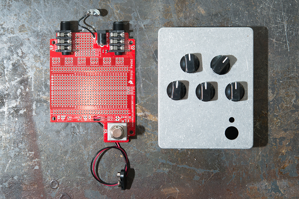
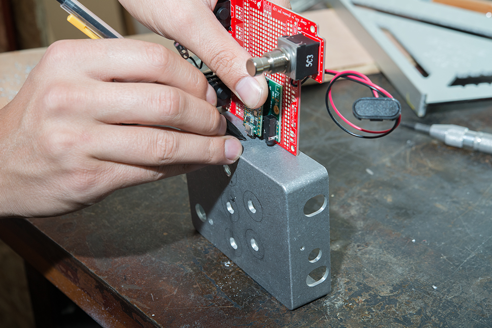
We had the circuit board nearby to use as a reference, to help see where internal objects are are located. We also had the assembled stack of Teensy 3.2 and Audio Adapter nearby, which we test fit several times as we worked. This allowed us to recognize that the stack doesn't stand much above the board, leaving vertical space to place a pot over it.
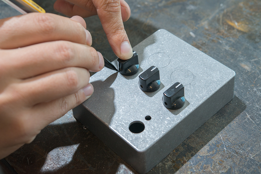
With the knobs in rough proximity of their ultimate destinations, we traced them in pencil, making circles on the box.
More Precise Layout
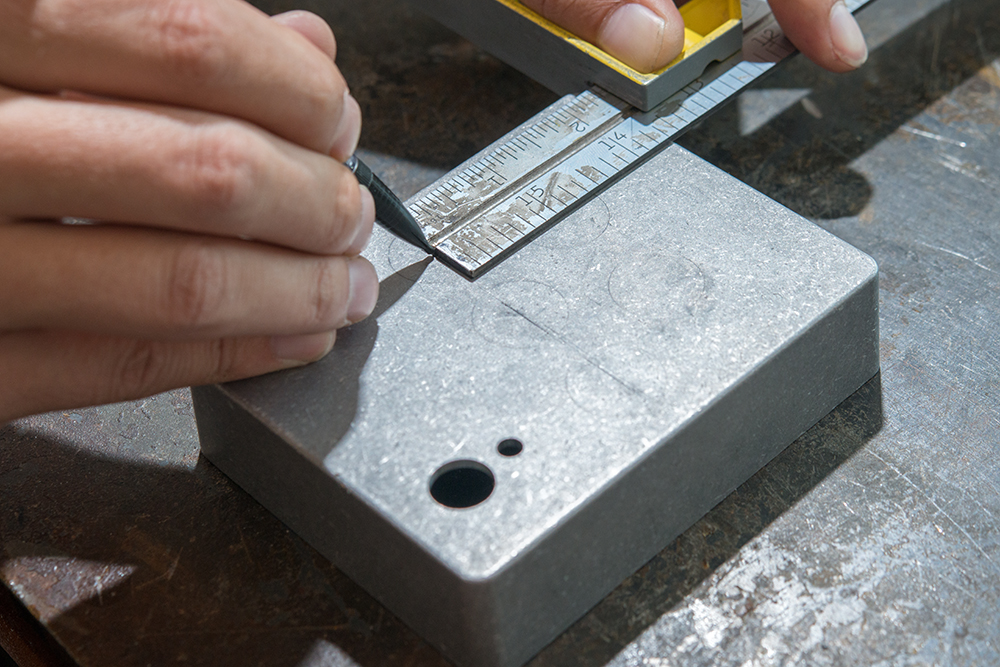
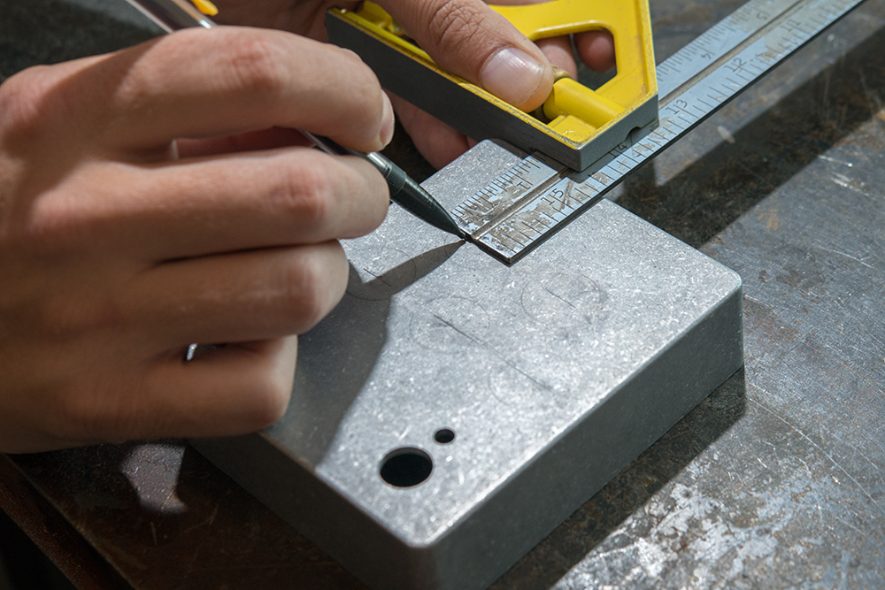
With the knobs removed, we measured the location of their centers from the top edge of the box. We averaged the measurements, so the holes would be in reasonable alignment.
Here we've marking a line 2 1/2 inches from the top edge, using a combination square to insure a consistent distance. If you don't have a square, you can carefully measure two points and draw a line between them.
The top row is an inch closer to the edge, at 1 1/2 inches.
With the lines for the rows drawn, we'll move on to the horizontal position of each pot within the rows.
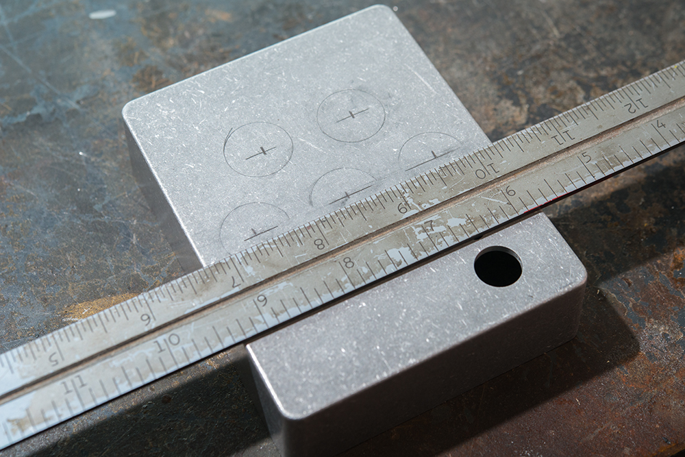
We decided to center these knobs, so we set the ruler on the box such that the edges aligned the same number of subdivisions past the last whole inch, or a little more than 1/4 inch, at 9 1/4 and 5 3/4. Now, the 8 1/2 inch mark is centered horizontally and we can count subdivisions out from there to make sure the holes are equally spaced.
The top row holes were marked 1/2 way between the marks in the bottom row, resulting in a regular "M" shape.
Notice that the rough knob outlines are no longer accurate to the center marks. The outlines were just eye-balled on for aesthetics, while the measured marks insure accuracy.
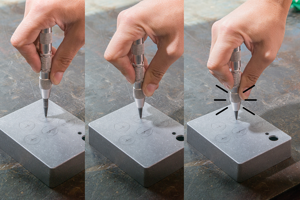
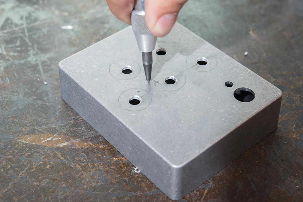
Punching
Punch the center of each hole. This will help guide the drill bit.
If you've never seen a spring loaded center punch before, they're really cool. Just press down until the internal spring is sprung, and it leaves a mark behind. You can get these at most hardware stores.
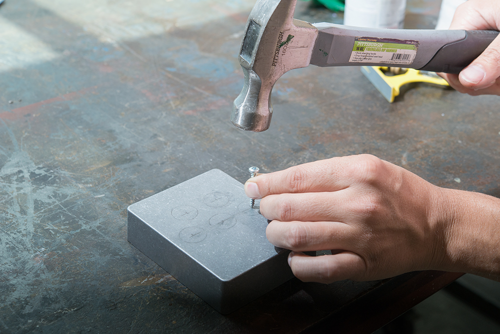
Or if you don't have a center punch, use a large screw and a hammer. Big pan heads work well, but wood deck screws or drywall screws are too pointy.
Now let's get to the real action!
Drilling
When you're happy with your center punch marks, it's time to start drilling.
Drilling Metal
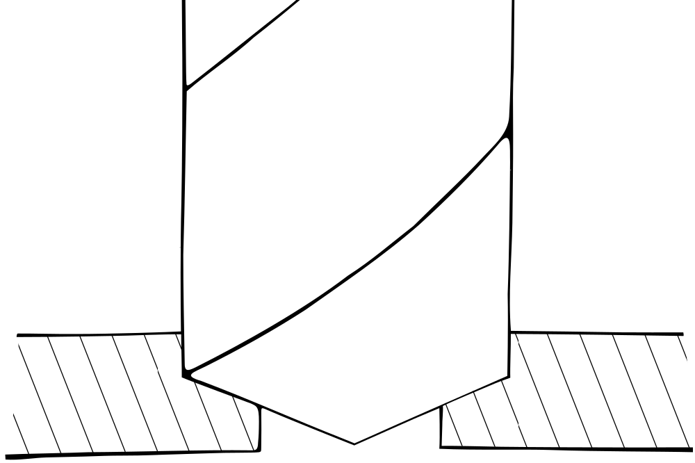
When drilling metal, it's important to start with a small pilot hole, and work progressively up to the desired size. For these holes, they'll be 5/16 inch for the 10k linear potentiometers. Each successive hole should be 25% to 50% larger than it's predecessor.
When drilling metal, use a moderately slow speed, and reasonable pressure. A drill that's too fast can cause the bit to overheat, and is more dangerous if you lose control.
Preparation
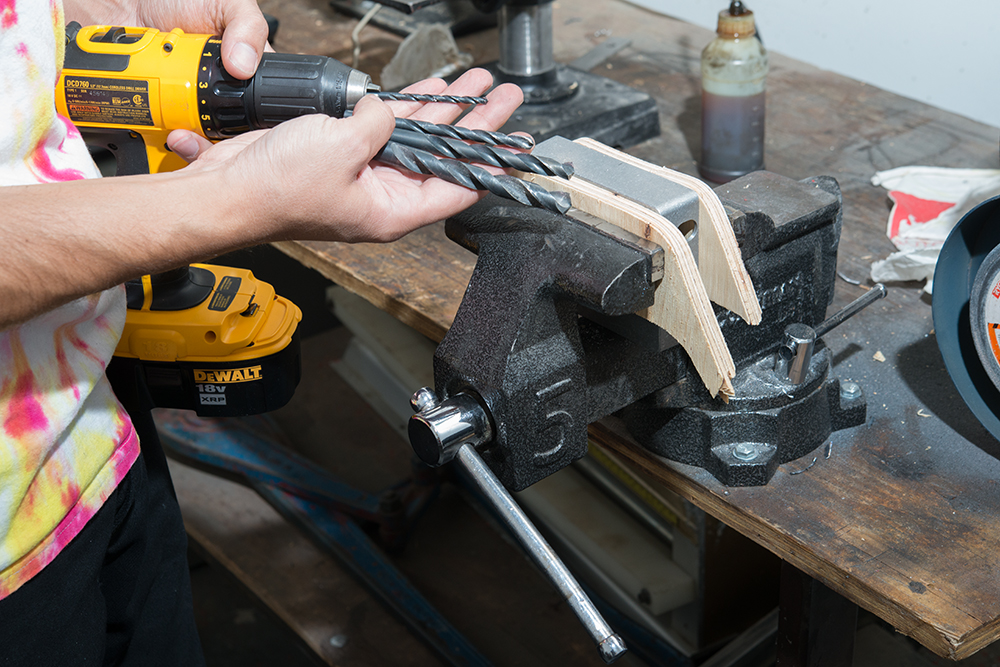
Before drilling, solidly secure the workpiece with a vice or a clamp.
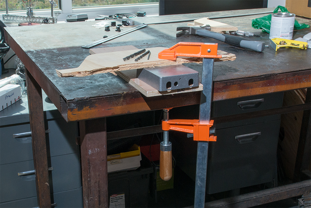
Here, three bits have been selected and the piece is clamped. You may think you can just hold the piece down with your hand, but more often than not it will wedge on the drill bit and spin around, whacking your hand and causing injury (and perhaps damaging the workpiece). Also, use scrap wood to protect the piece from marring, and to provide something soft for the drill bits to crash into when they break through.
Drilling
Start with a small pilot hole. This is the most important drill as it will guide the other holes.

A challenge with using a hand drill is maintaining perpendicularly to the work surface. As a reference, set a square on the piece and use it as a visual guide. Before you start drilling, hold the drill where you think it should go and move your head around like an owl to see that you've got good alignment from all angles.
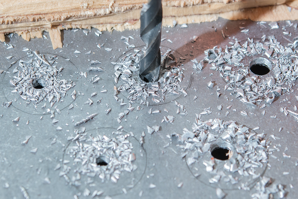
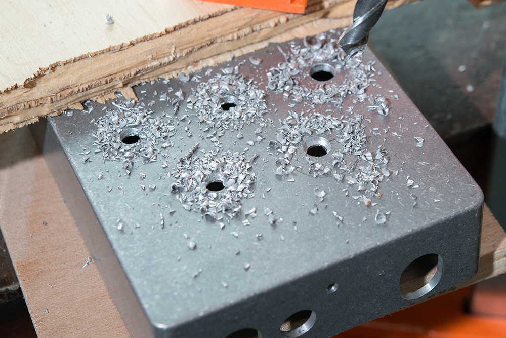
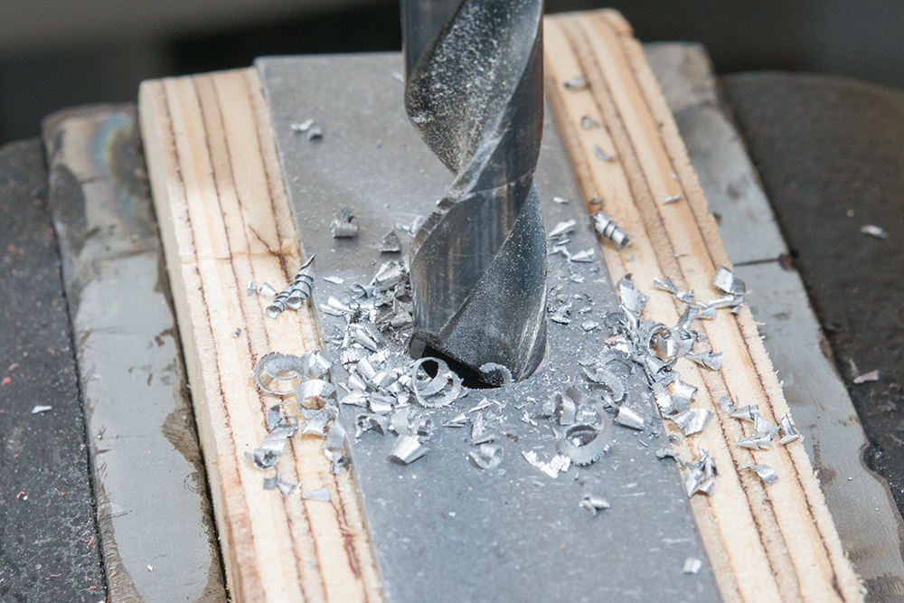
When you're ready, drill with a medium speed and decent pressure. The bit should produce a constant stream of waste material. If it seems like it's just spinning, doublecheck you're not in reverse, try adding more pressure, or slow the drill speed.
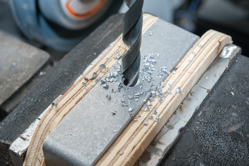
After the pilot holes are complete, move up to the next larger bit, and use it to enlarge each hole. As you move to larger and larger bits, less speed should be required.
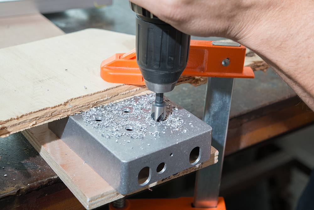
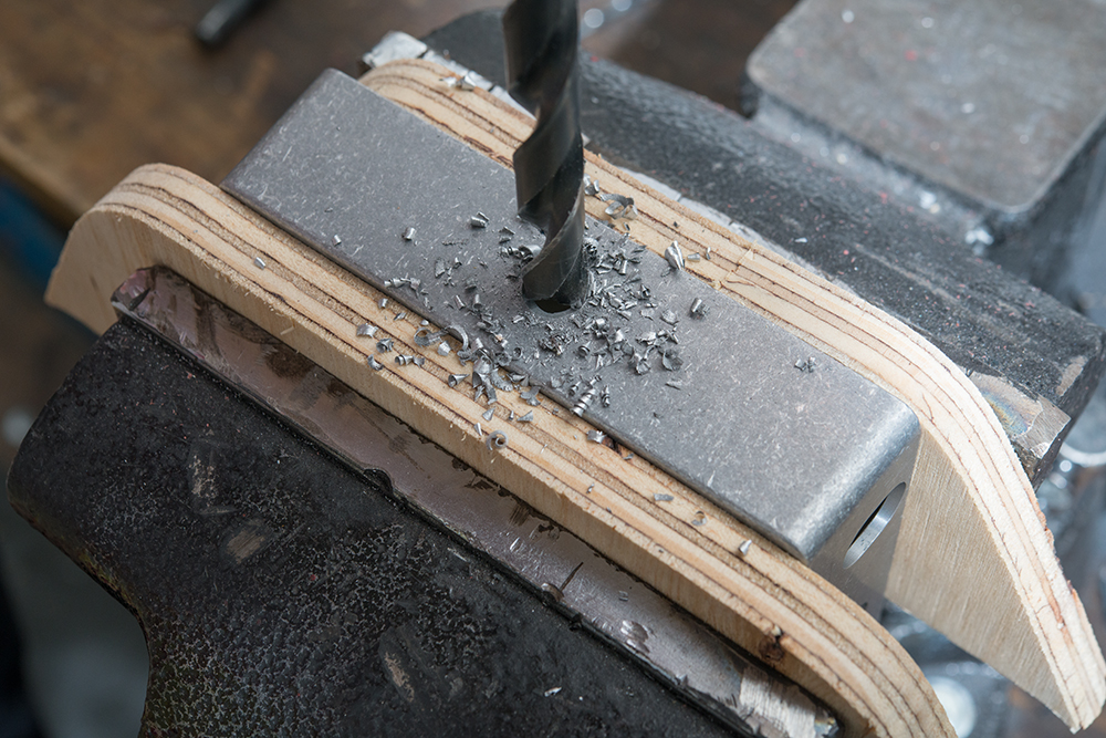
After an intermediate hole, we can drill the final hole, 5/16 inch.
The drill has been stopped partway through to show the overlap detail (lower right).
The drilled holes frequently have a sharp burr around the edge. If you like, you can bevel the edges with a chamfer tool, or clean them up with a file. It's not required, but will get rid of the sharp edges.
Notes for Potentiometers
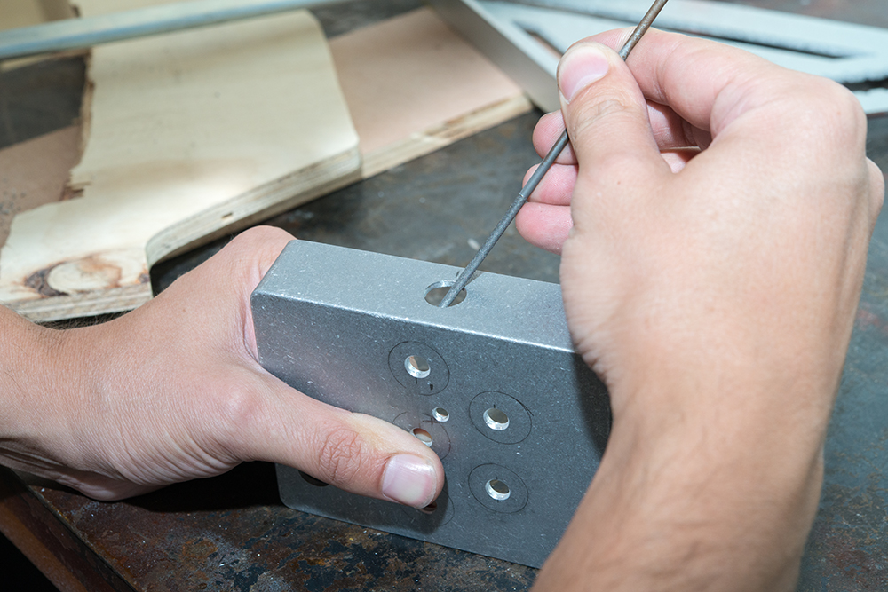
The potentiometers have an alignment / retention boss. You can either drill an extra hole to retain it, or trim it off with a pair of side cutters.

Extra holes for the Teensy
For the Teensy based digital pedal, we're going to add a couple extra holes. The first is one on the side of the chassis for the USB connector, plus a second smaller hole in the top of the pdeal, so we can reach the manual-load button.
As with our initial layout, we're going to do it empirically, using the final parts to gauge where the holes need to be. We started with the USB port, measuring on the left side of the enclosure.
Programming Port
First, choose the location of the programming hole based on where you want the Teensy to be in the pedal. Use the circuit board as a guide, aligning the 1/4 inch jack shoulders to the inside plane.
Approximate the height of the hole by holding the circuit board where it will sit when assembled, and cross the previous mark.
Then, punch a center point, and move on to drilling.
We going all the way up to our largest drill, to accommodate the USB plug molding, making 4 drills overall. This time, were using a vice to hold the workpiece, again using blocks of wood to protect it.
As before, we're working progressively up to the larger drills.
Since this hole is larger, there will be two intermediate drills.
Watch the quality of the waste material. It's a good sign that speeds and pressures are correct when the waste forms into curls rather than little chips. Also, it can be seen here that the overlap is quite small for this large bit. Otherwise, the bit would have a great tendency to catch when getting close to being through.
Once the drilling is complete, we want to chamfer the edges of the hole. The chamfer is more important for this hole, because the sharp edge won't be covered with a control. This time, the hole is as large as the bit were were chamfering with before, so we have to do it manually, with a file.
Reset Switch
We used a similar triangulation process for the hole for the button. Here, there's a mark where it should be, but that is underneath a knob. The hole was moved outside of the knob outlines, and will have to be used at a slight angle.
Since this hole is smaller, we didn't need to step through as many drills.
Painting
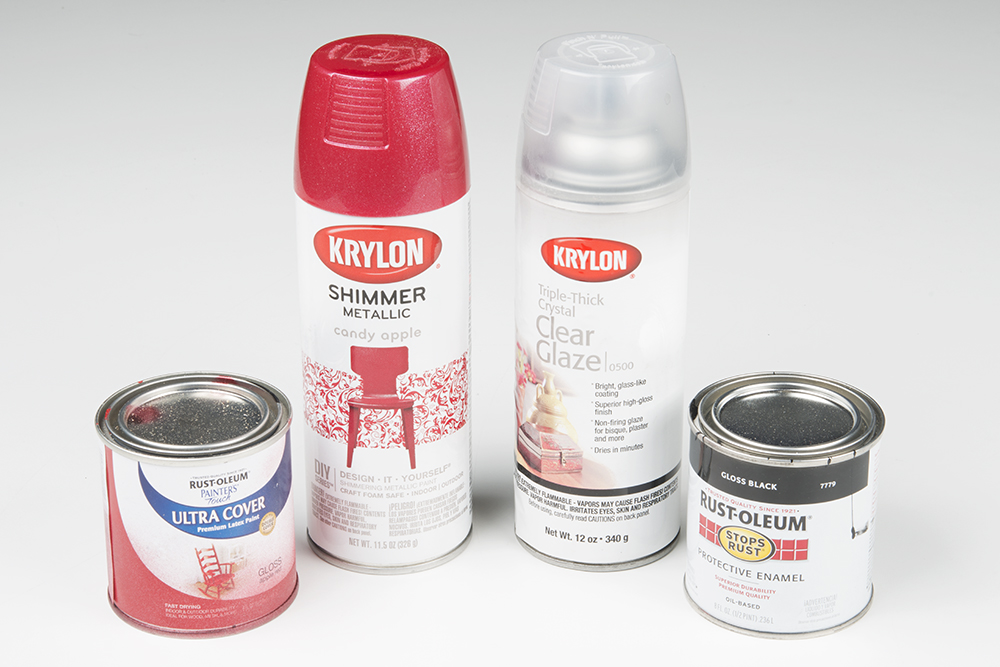
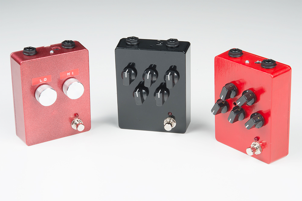
For a finishing touch, you can paint your pedal. We've chosen to try out a couple Rust-Oleum oil-based enamels, which have wildly different properties based on the color, and a spray job using red Krylon Shimmer spray paint, with a clear overcoat.
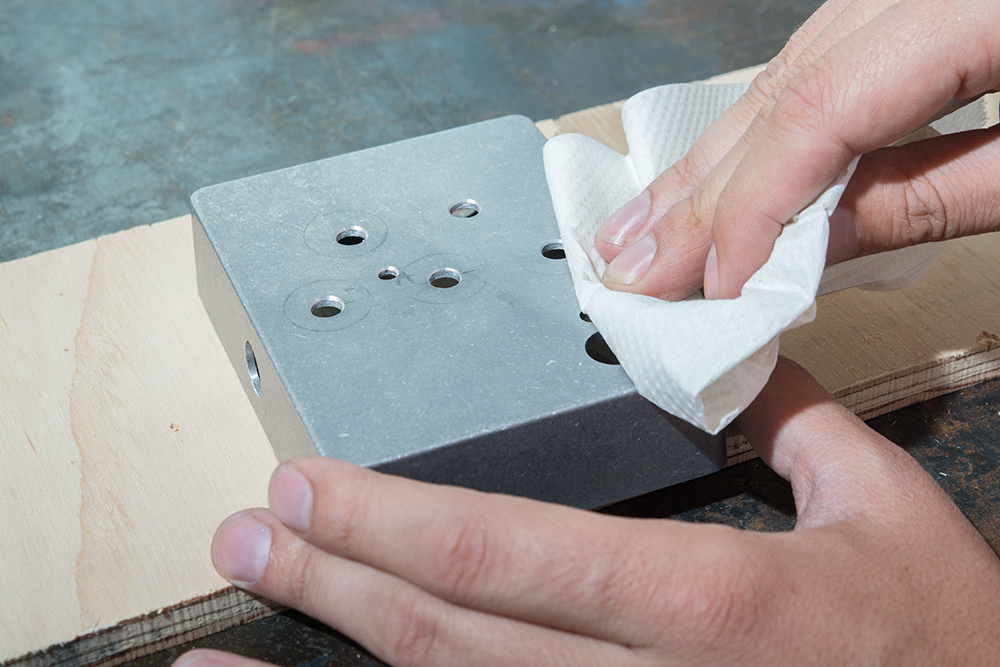
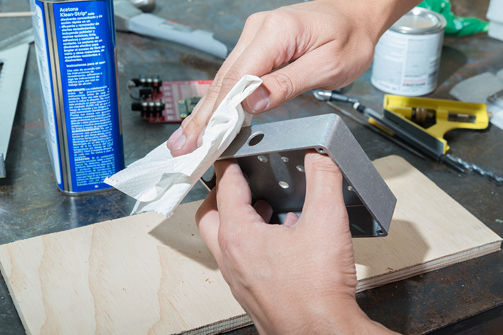
Start by cleaning the case with acetone or isopropyl alcohol. This removes oils and pencil marks.
The liquid paint was applied using a foam applicator wedge.

Painting can be a messy process, and you're likely to get some on your work surface. You can protect against paint slop with a drop cloth, or other scrap materials, such as wood, or cardboard.

You can paint the faces of the screws too, if you wish, but try not to get any into the threaded holes, or they may be difficult to drive.
Painting Results
You can see that the red paint tended to pile up and stay streaky, and needs to be sanded and coated again. This paint should probably be used with a sprayer or thinned out. The black leveled well and could be sanded to a decent finish, but the red refused to level as can be seen above. The Shimmer paint was pretty much fabulous.
Resources and Going Further
Don't know what to put in your case? Try these!
- If you're interested in analog circuitry, check out the analog EQ pedal example project.
- If you're more familiar with writing software and want to design effects by writing programs, check out the programmable digital pedal example.
Have fun decorating and labeling your new proto pedal, and rock on!