$2.75
Do you need to power a project with 12V and 5V from one wall adapter? The ATX power connector breaks out the standard 4-pin computer peripheral port for your 12V and 5V devices!
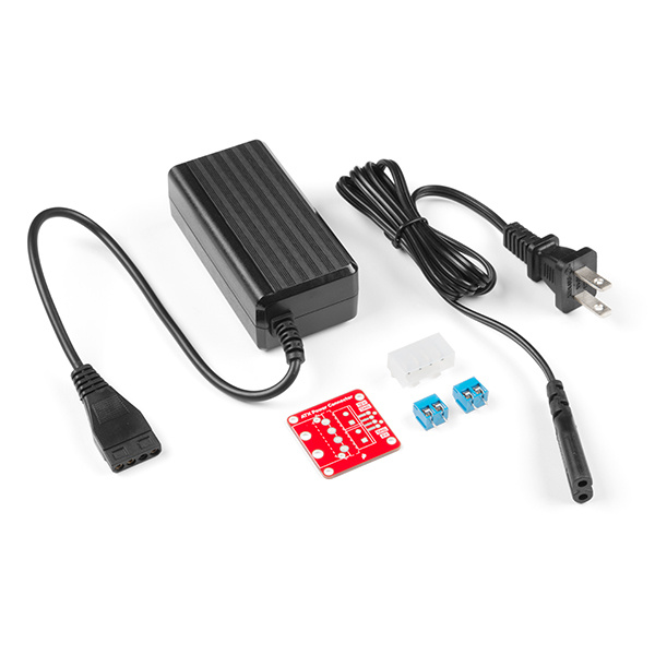
To follow along with this tutorial, you will need the following materials that are included in the kit. The components can be ordered individually if you decide to solder header pins or wires directly to the board. You may not need everything though depending on what you have. Add it to your cart, read through the guide, and adjust the cart as necessary.
You will need a soldering iron, solder, and general soldering accessories.
If you aren’t familiar with the following concepts, we recommend checking out these tutorials before continuing.
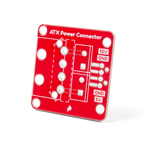
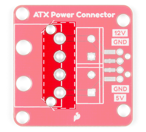
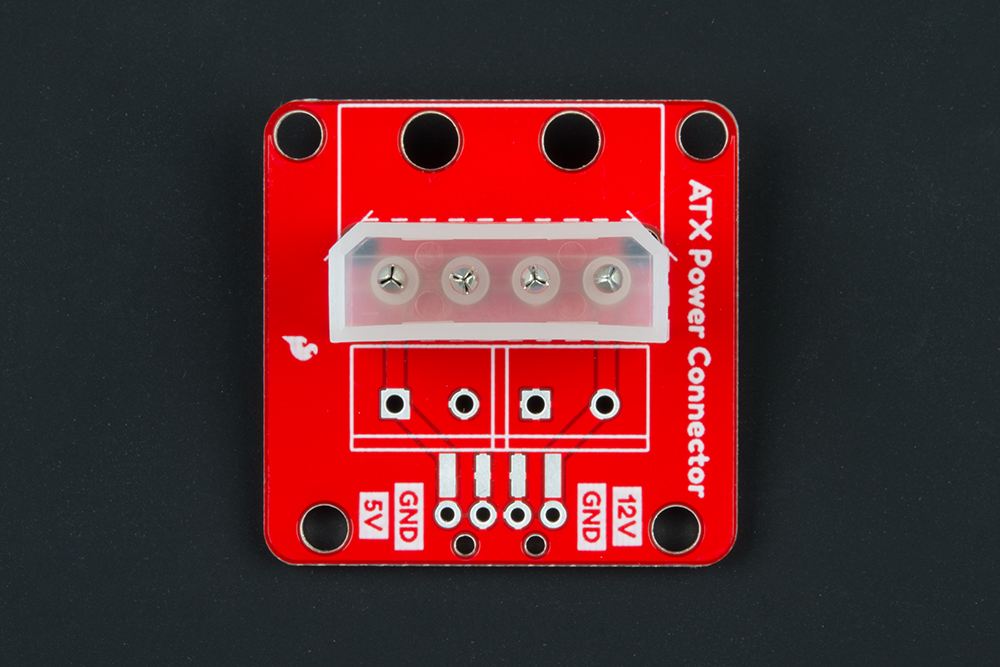
The board has the option of soldering a 4-pin right angle ATX power connector.
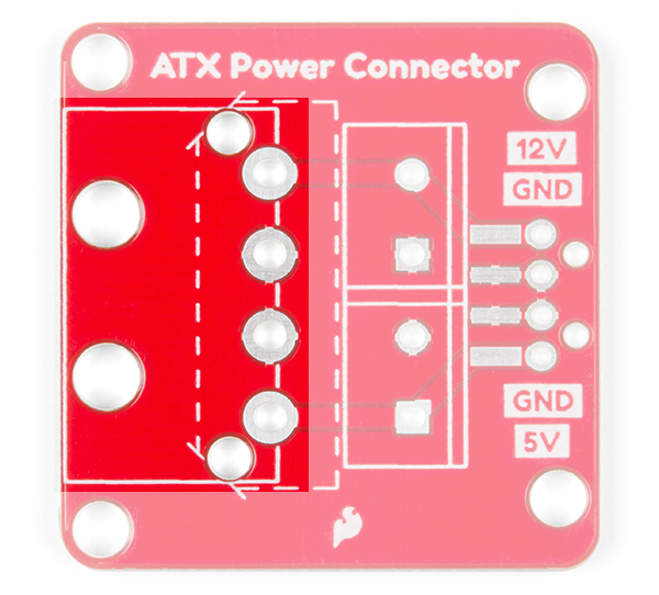
Depending on your application, you may want to add a vertical connector. Have no fear! The PTH pads were adjusted so that a 4-pin vertical connector can be added. Just follow the dashed silkscreen that outlines the perimeter of the connector.
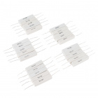
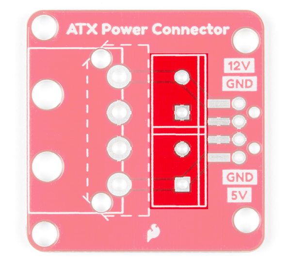
On the output side of the breakout, there is a spot for two 2-pin 5mm screw terminals.
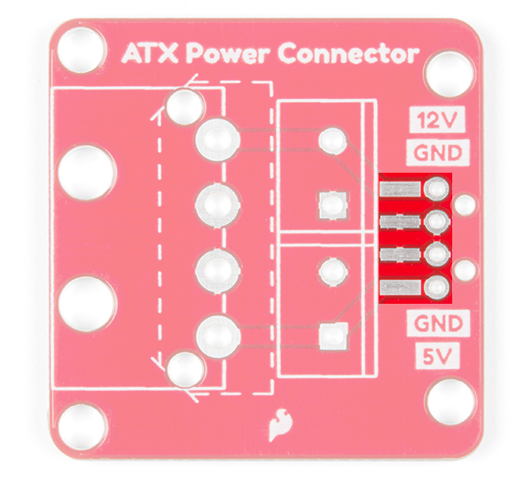
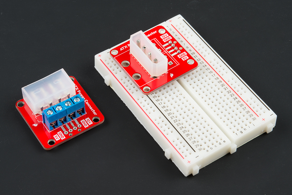
There is also an option of adding vertical or SMD right angle header pins if you need to connect the breakout to a breadboard or jumper wires. Just keep in mind that the amount of current the headers can handle is less than the screw terminals.
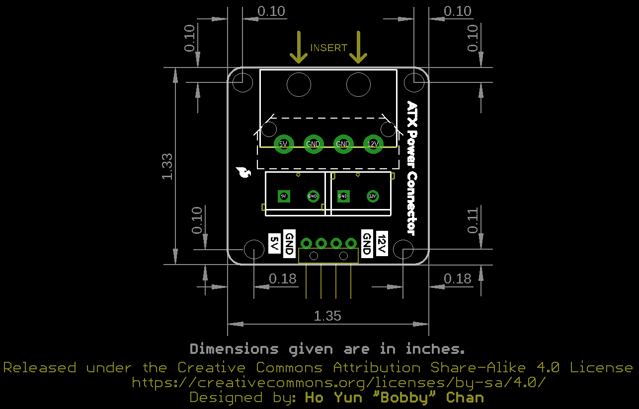
The board is 1.33in x 1.35in and includes four mounting holes to secure the board on a panel or enclosure.
You'll need to solder the connectors of your choice to the breakout. If you have not soldered before, check out our tutorial below for tips!
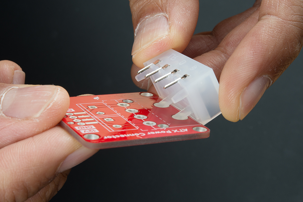
You'll need to decide on an ATX connector to solder on the breakout board. The board is compatible with both right angle and vertical connectors. We'll be using the right angle connector since the board is available in SparkFun's catalog. When inserting the right angle connector, make sure to insert the support legs first before inserting the pins into the through hole pads.
 |
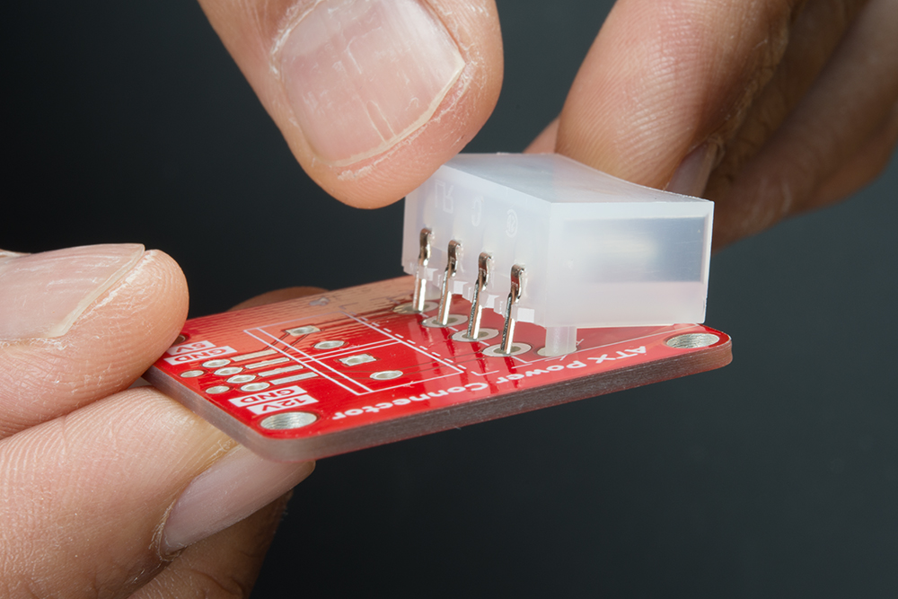 |
| Insert Support Leg into Breakout | Sliding Pins into Breakout |
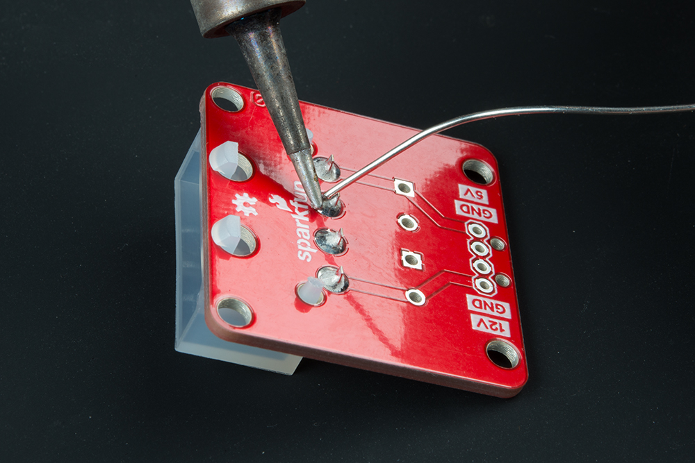
Once you have chosen the ATX connector of your choice, solder each pin to the breakout.
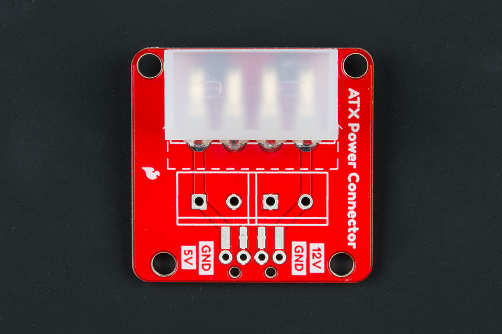
Your board should look similar to the image to the left for the right angle connector. If you happen to have a vertical connector from a different distributor, your board should look similar to the image on the right.
 |
 |
| Right Angle Connector Soldered | Vertical Connector Soldered |
Depending on your application, you can solder screw terminals or header pins to the breakout. With the screw terminals you can easily secure fork connectors or wires. If you choose the screw terminal route, you may need to strip wires before tightening the screws down for each respective pin. Should you decide to solder straight header pins, you can insert the board into a breadboard or protoboard. There is also an option to solder right angle SMD headers to the board as well depending on your application. Below are a few configurations depending on the connector and header that you choose. Remember, the SparkFun catalog only has the right angle connector available.
Below are options where you will encounter the 4-pin connector.
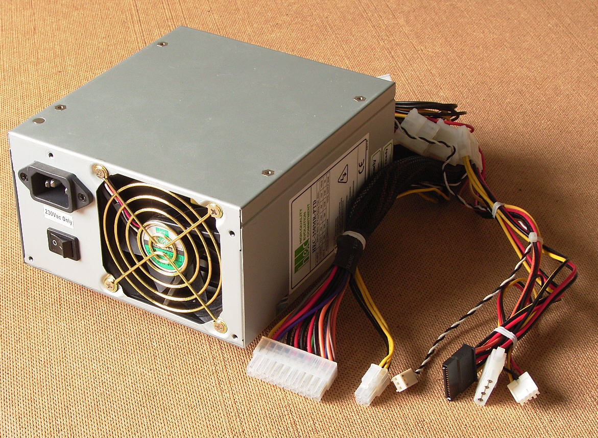
ATX power supplies usually have a number of power connectors available to power components for a desktop computer. The connector of interest in the image below is the second connector from the right. This 4-pin power connector is intended to power 12V and 5V computer peripherals (such as disk drives). Depending on the manufacturer of the power supply, the quantity of each connector can vary. If you want to grab some juice for your project from this type of power supply, you'll need to connect the breakout board to this port.
Certain wall adapters also take advantage of this standard 4-pin port like the 12V/5V (2A) power supply in the catalog. If your project requires either/both 12V and 5V for power you can also connect the breakout board to this power supply.
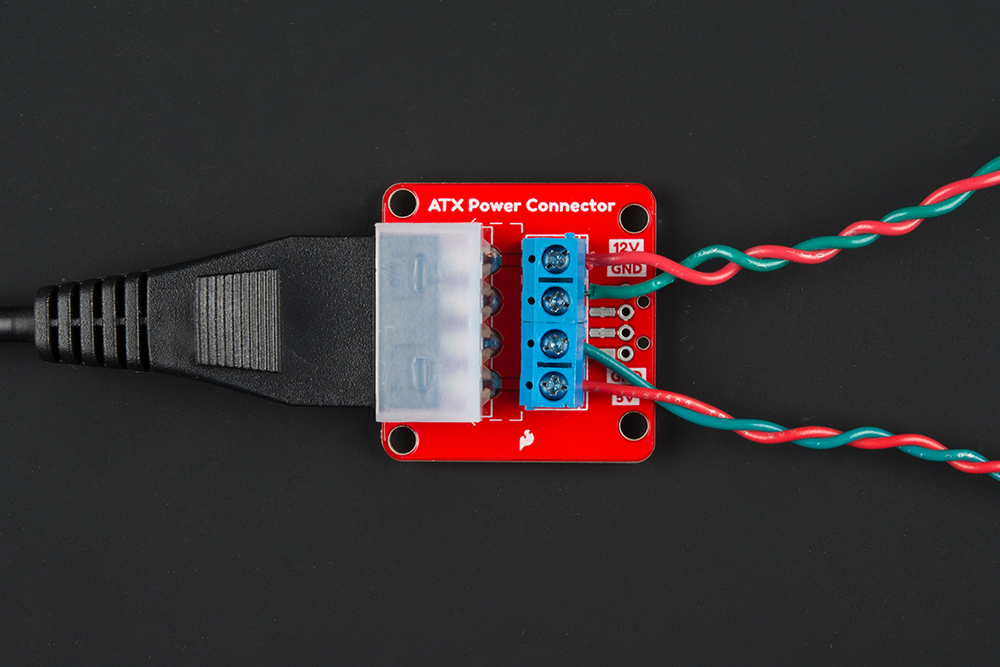
Once you have chosen your ATX power supply, you're ready to give your project some life! You can use the board to help power your microcontroller and LEDs from either side depending on your application. Check out the following tutorials below for examples of using a 12V/5V power supply.
For more information, check out the resources below:
Need more inspiration for your next project? Check out some of these related tutorials that uses the 12V/5V (2A) power supply.
Or check out some of these blog posts about power supplies.
learn.sparkfun.com | CC BY-SA 3.0 | SparkFun Electronics | Niwot, Colorado