Atto84 Hookup Guide
Introduction: The Littlest 'Duino

Experimental Products: SparkX products are rapidly produced to bring you the most cutting edge technology as it becomes available. These products are tested but come with no guarantees. Live technical support is not available for SparkX products.
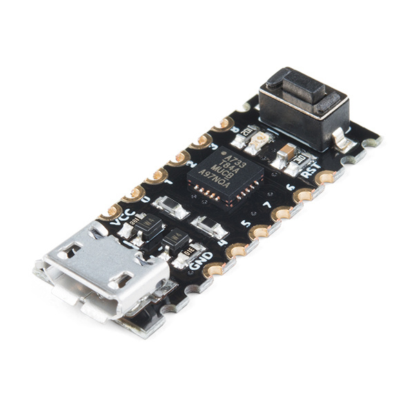
Arduino and Arduino compatible dev boards are an awesome tool for developing an idea quickly but, being development boards, they're often a little more bulky and full featured than you really need. Having a USB interface and a bootloader is so nice, though, so we put together the bare minimum Arduino compatible breakout for integration into your small projects. We call it the Atto84.
Atto84 with Arduino Bootloader
SPX-14804The Atto84 is essentially a breakout board for the absolutely minute WQFN ATtiny84, but we've done some work to make it easier to program. First off, we've added a micro-USB connector and a firmware-based USB driver for the ATtiny that allows you to program the chip over USB. In addition, we've created an Arduino board profile that combines this bootloader with an extremely full-featured ATtiny Arduino core.
Simply install the USB drivers on your computer, select the board profile from Arduino's Board Manager, and upload code to this board like any other Arduino style development board. In this hookup guide, you'll learn how to do exactly that!
Suggested Reading
If you aren’t familiar with the following concepts, we recommend checking out these tutorials.
Serial Peripheral Interface (SPI)
I2C
How to Solder: Castellated Mounting Holes
How to Install an ATtiny Bootloader With Virtual USB
Installing USB Drivers
The Atto84 is emulating USB 1.1 using two of its pins and the V-USB driver. However, there are no common operating system drivers available that work with this custom USB class. As a result, we will need to install custom drivers in order to communicate with (and send our Arduino programs to) the Atto84. Choose your operating system below and follow the directions to install the driver.
Windows
Insert a micro-USB cable into the Atto84. Your PC will probably make a happy "USB connected!" chime and then inform you that there is an unknown device connected.
Download the SparkFun ATtiny USB drivers by clicking on the link below.
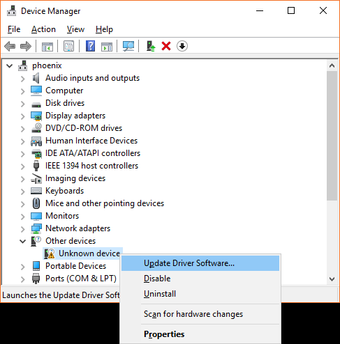
Unzip the file. Open the Windows Device Manager, and you should see an Unknown device. Right-click on Unknown device and select Update Driver Software.
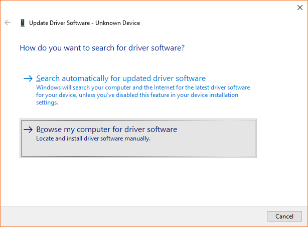
In the pop-up window, click Browse my computer for driver software.
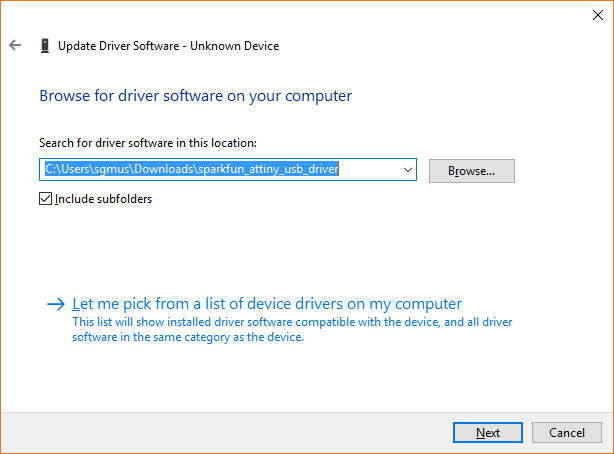
Click Browse... and open the folder that contains the drivers you just unzipped. It will likely be the sparkfun_attiny_usb_driver folder.
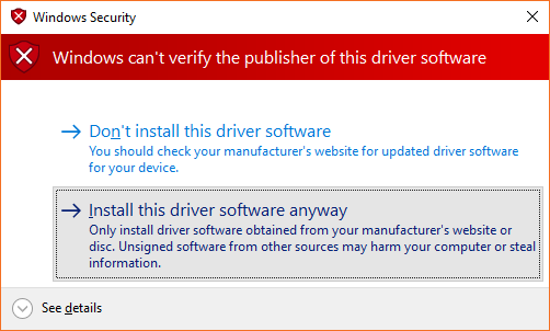
Click Next. You may get a warning pop-up that says "Windows can't verify the publisher of this driver software." That's OK. Just click Install the driver software anyway.
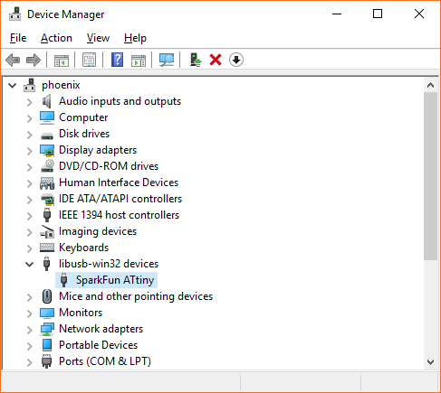
You should see a notification that the SparkFun ATtiny driver was installed successfully. Close that window, and verify that your Unknown device now shows up as SparkFun ATtiny in the Device Manager.
Mac OS
You'll need to install Homebrew and use it to install libusb. Enter the following commands into a Terminal:
language:bash
/usr/bin/ruby -e "$(curl -fsSL https://raw.githubusercontent.com/Homebrew/install/master/install)"
brew doctor
brew install libusb-compat
Linux
Good news! Linux doesn't require special drivers. However, you will need to do one of the following to be able to program the Atto84 from Arduino:
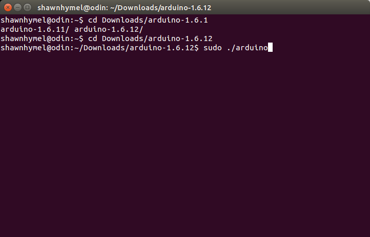
1) When you download the Arduino IDE (next section), make sure you run it as root: sudo ./arduino
2) Or, you can add some udev rules so that Linux enumerates your device with write permissions. Create a file in rules.d:
language:bash
sudo edit /etc/udev/rules.d/49-micronucleus.rules
Copy the following contents into that file:
language:bash
# UDEV Rules for Micronucleus boards including the Digispark.
# This file must be placed at:
#
# /etc/udev/rules.d/49-micronucleus.rules    (preferred location)
#   or
# /lib/udev/rules.d/49-micronucleus.rules    (req'd on some broken systems)
#
# After this file is copied, physically unplug and reconnect the board.
#
SUBSYSTEMS=="usb", ATTRS{idVendor}=="16d0", ATTRS{idProduct}=="0753", MODE:="0666"
KERNEL=="ttyACM*", ATTRS{idVendor}=="16d0", ATTRS{idProduct}=="0753", MODE:="0666", ENV{ID_MM_DEVICE_IGNORE}="1"
#
# If you share your linux system with other users, or just don't like the
# idea of write permission for everybody, you can replace MODE:="0666" with
# OWNER:="yourusername" to create the device owned by you, or with
# GROUP:="somegroupname" and mange access using standard unix groups.
Save and exit.
Installing the Board Package
Important! Your Atto84 will only work with Arduino versions 1.6.10 and above. If this is your first time using Arduino, please review our tutorial on installing the Arduino IDE.
Download and Install the Board Package
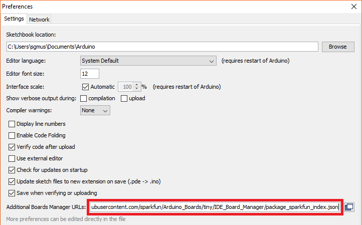
Because the Atto84 is not supported by the Arduino IDE by default, we need to add it manually. Open the Arduino program and go to File > Preferences. Then copy and paste the URL below into the Additional Board Manager URLs text box.
If you're thinking "I already have the SparkFun Board Profiles and I don't see any tiny boards!" notice that we're specifically pointing to a branch of SparkFun's Arduino Boards repository called ".../tiny," not the main branch. If you copy/paste the URL below, you should have no troubles!
https://raw.githubusercontent.com/sparkfun/Arduino_Boards/tiny/IDE_Board_Manager/package_sparkfun_tiny_index.json
Then hit OK, and navigate to the Tools > Board > Boards Manager… tool. A search for “tiny” should turn up a SparkFun ATtiny Boards result. Select that and click Install.
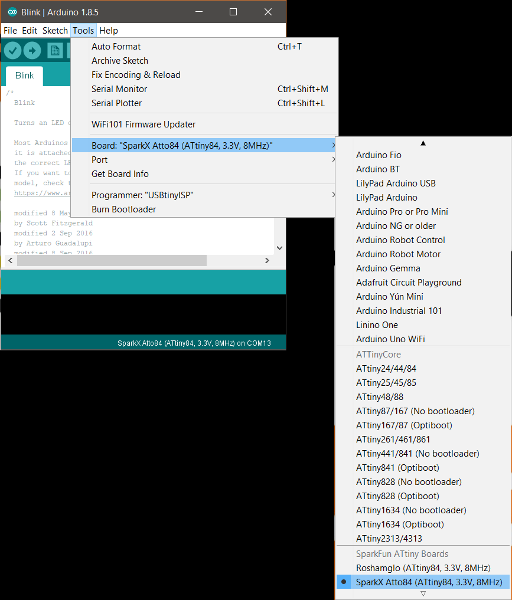
Once the installation is complete, go to Tools > Board and select SparkX Atto84 (ATtiny84, 3.3V, 8MHz) under the SparkFun ATtiny Boards section.
Tiny Tricks and Gotchas
Tiny Tricks
Because the Atto84 is the bare-minimum of hardware that can be USB programmed, it does have a few quirks that you should be aware of. But first, let's talk about a few of the cool features that it inherits from SpenceKonde's ATTiny Core.
I²C Support
The ATTiny Core includes a special version of the Wire library that leverages the tiny84's hardware USI for I²C communication. This means that it will run any Wire-based code that you've written for ATmega platforms like the Arduino Uno or the SparkFun RedBoard.
SPI Support
The ATtiny actually has hardware SPI support, so the Atto84 will work identically to the Uno in that respect.
Servos?
Yeah, why not? The tiny84 has plenty of timers and you'll find a copy of the Servo library included with the core!
The "Gotchas"
Sounds great, right? It is, but there are a few catches that you should be aware of.
Power
There is no power regulator on the Atto84, so the input to VCC must be between 3.3V and 5V. Powering your project through the USB connector is a good, too.
Serial UART
The ATtiny doesn't have a hardware UART, so serial doesn't work the way you might expect. There is a custom library built in to the ATTiny Core called "Serial" which is actually an implementation of Software Serial. This works quite well but you do need to know its limitations. For instance, it's not full duplex, so sending and receiving at the same time will produce gibberish. Also, it does not implement V_USB, so if you want to do Serial debugging, you'll need to connect a separate USB-Serial adapter.
Uploading Code
Most USB Arduino boards can be forced into bootloader mode by the Arduino IDE during programming, but due to the limitations of V-USB, the Atto84 needs to be manually reset during programming. Every time the Atto84 restarts, it goes into bootloader mode for about 5 seconds. During this time, your computer will recognize it as a USB device. After 5 seconds, the Atto84 begins running user code. Unless your code also happens to be implementing V-USB, the computer will stop recognizing the device.
In order to get code onto the board, simply click the upload button in the Arduino IDE and wait for the "uploading..." message to show. When the IDE says "uploading," press the reset button on your Atto84. Don't worry, the timing isn't critical, the Micronucleus upload program gives you 30 seconds to press reset. After the board has reset and shows up as a USB device, your code will upload like normal!
- Try a different USB port
- Unplug other USB devices
- Close other programs that might be running
- Reinstall the Atto84 USB driver
- Try a different computer
Resources and Going Further
For more information about the Atto84, check out the resources below:
- Schematic (PDF)
- Eagle Files (ZIP)
- V-USB
- SparkX Landing Page
- GitHub
- Product Repo
- Arduino Boards: ATtiny - ATtiny84 branch for the Atto084
Need some inspiration? Check out these Arduino based projects!
