Ardumoto Shield Kit Hookup Guide
This Tutorial is Retired!
This tutorial covers concepts or technologies that are no longer current. It's still here for you to read and enjoy, but may not be as useful as our newest tutorials.
View the updated tutorial: Ardumoto Kit Hookup Guide
 jimblom
Ardumoto Overview
Before you get your soldering iron out, or start attaching motors, it'd be best if we briefly covered the basics of the Ardumoto Shield. On this page, we'll highlight the important inputs and outputs of the shield, so you can get a better idea of how you want to assemble it later.
Pins and Connectors
Here's an annotated view of the shield, highlighting the important pins and components:
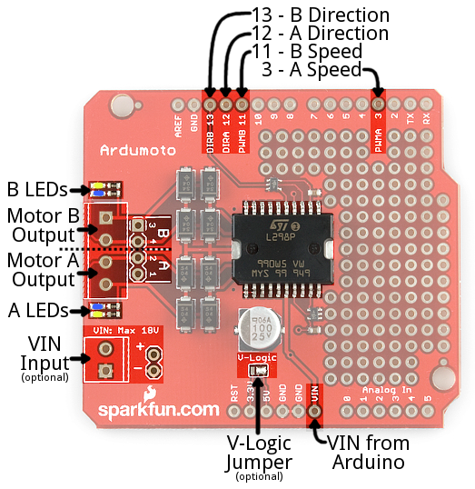
The Ardumoto Shield lays claim to four Arduino pins: 3, 11, 12, and 13. Each motor uses two pins -- one for direction, the other controls the speed.
| Arduino Pin | Ardumoto Shield Pin Label | Notes |
|---|---|---|
| 3 | PWM A | A PWM signal to control the speed of motor A. 0=off, 255=max speed. |
| 11 | PWM B | A PWM signal to control the speed of motor B. 0=off, 255=max speed. |
| 12 | DIR A | A digital signal to control the rotation direction of motor A (e.g. HIGH/LOW => CW/CCW). |
| 13 | DIR B | A digital signal to control the rotation direction of motor B (e.g. HIGH/LOW => CW/CCW). |
While the Ardumoto Shield is attached to an Arduino, these pins shouldn't be connected to anything else.
Motor Outputs
Both of the L298's motor driver outputs are broken out to the left-edge of the shield. These 2-pin outputs are broken out to two footprints: a 3.5mm-pitch screw terminal and a 0.1"-pitch header. You can use either to wire up your motor, but screw terminals make life much easier if you need to disconnect your motor. The L298 is perfect for building simple 2 wheel drive robot platforms -- connect one motor to port A and the other motor to port B.
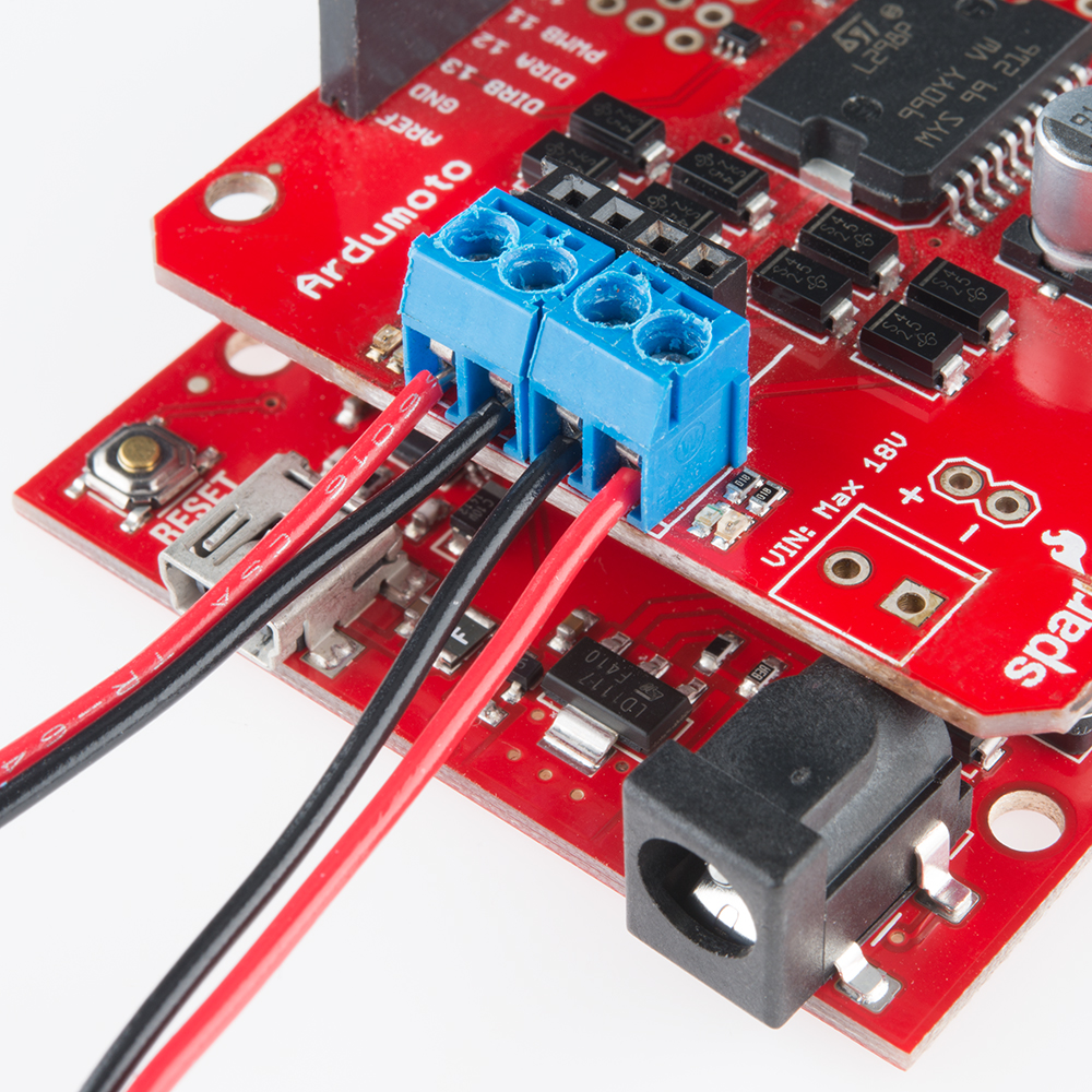
Technically, there is no right or wrong way to connect your motor's wires to the two output pins, but to help keep things straight, we suggest connecting the red / black wire for each motor to pins 1 / 2 on port A and pin 3 / 4 on port B, respectively.
Don't worry if you swap this, the direction control of the motor will just be swapped as well.
LED Indicators
Next to each of the motor outputs are a pair of blue and yellow LEDs, which indicate the direction your motor is spinning. These are great once you get to debugging your project. They're also useful if you want to test your sketch without wiring up any motors.
Supply Voltage
The Ardumoto Shield should be powered through one of two power supply inputs. Pick one or the other:
- The barrel jack input on the Arduino.
- The VIN input on the shield
If you don't want to use the Arduino's barrel jack input, you can use the VIN input on the shield instead. This voltage input will supply both the shield and the Arduino. Like the motor outputs, this connection is broken out to both a 3.5mm screw terminal and a 0.1"-pitch header.
Do not supply power to both the Arduino barrel jack input and VIN on the shield!
Spec'ing a Power Supply
Because VIN powers both your Arduino and your motors, you need to take extra care in deciding what you'll use to power your Arduino/Ardumoto combo. Not only does VIN have to fall within the acceptable range of your Arduino (usually 6-15V), but it also has to meet the specifications of your motor.
Check the voltage and current requirements of your motor before deciding how to power your Ardumoto project. These specifications vary. The 65RPM Hobby Gearmotors, for example, have a recommended range of 3-6V, but can be safely powered at up to 9V.
We recommend 9V Alkaline Batteries as an easy, if not-very-sustainable option. Dual-cell LiPo battery packs (7.4V nominal, 1000mAh capacity) are also a good option if you're looking for something mobile. A 9V wall wart can work if your project is stationary. For more help picking a power supply, check out our How to Power a Project tutorial.