Ardumoto Kit Hookup Guide
 jimblom,
  MTaylor
 Introduction
The Ardumoto Shield is a dual-motor controller for Arduino. Combined with an Arduino, the Ardumoto makes a fantastic controller platform for RC vehicles or even small autonomous robots. It's now easier to use, featuring control signal LEDs, while also being much more flexible for advanced users.
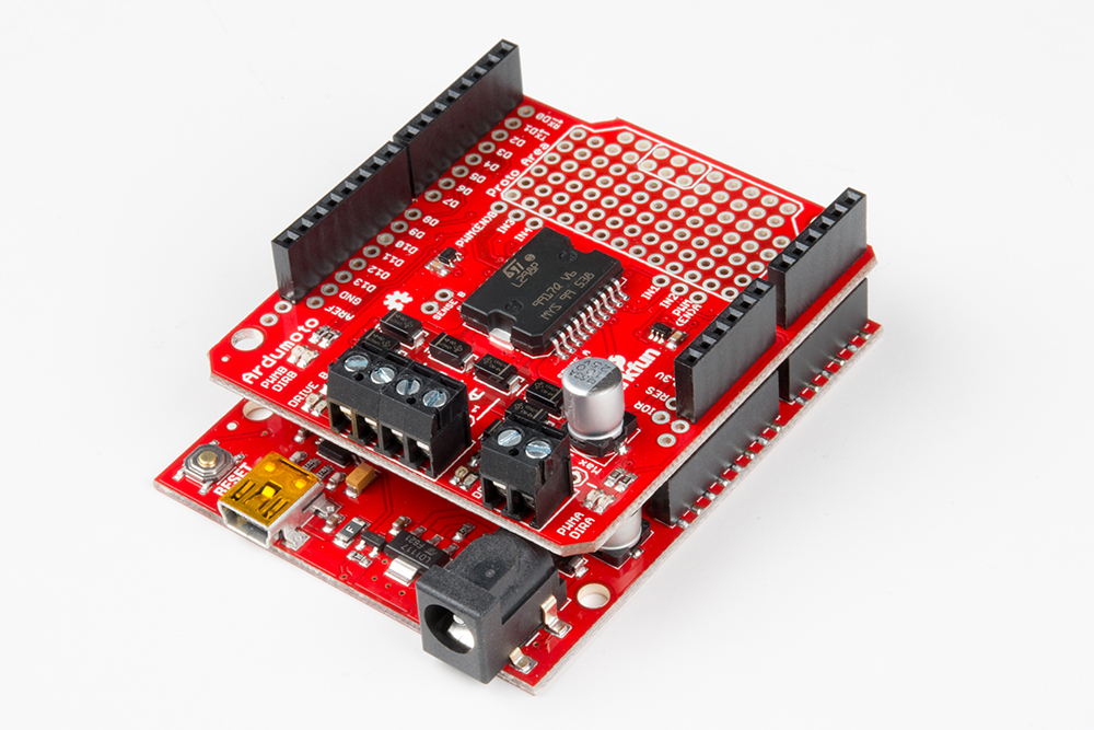
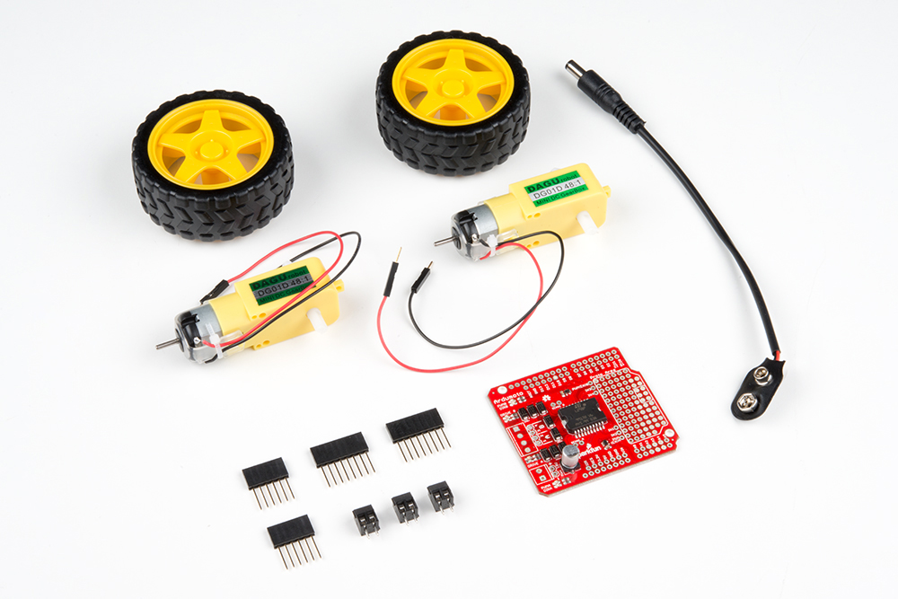
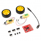
We sell the Ardumoto Shield either alone or with a set of motors and wheels in our Ardumoto Shield Kit. This kit includes the shield as well as pairs of tires, motors and connectors. And, of course, it's all stuffed in a classic SparkFun red box (which may come in handy as a robot chassis).
Covered in This Tutorial
This tutorial covers assembly and use of both the Ardumoto Shield and the Ardumoto Shield Kit. Digging deeper, we'll get into some assembly tips and an example Arduino sketch. We will also present some additional resources that can help you get the most out of your board.
This guide assumes you are familiar with the Arduino platform and can successfully compile and load a program to an ATmega328P based board, such as blink.ino.
Required Tools & Materials
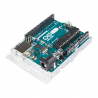
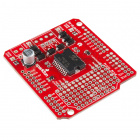
To follow along with this tutorial, you'll need an Ardumoto Shield or the Ardumoto Shield Kit, and an Arduino or Arduino-compatible development board.

Equipping the Ardumoto Shield (Non-Kit Version)
If all you have is the shield, you will also probably want a couple of DC motors to drive. The Ardumoto can control most small DC motors, like any of those in our DC motor category.
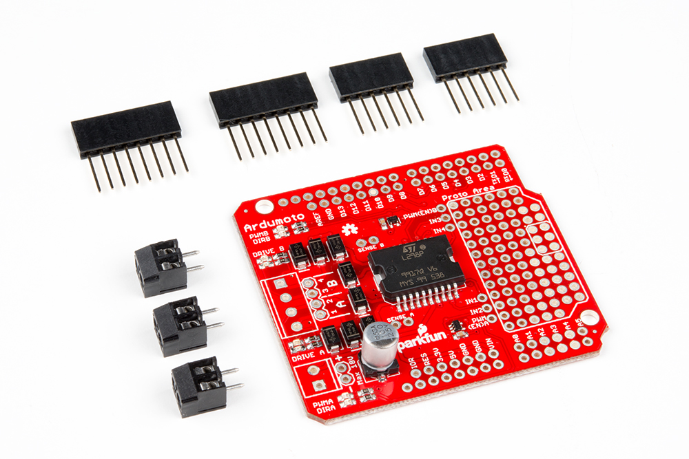
You'll also need a handful of connectors to get everything wired up together. We recommend Stackable Headers to connect your Ardumoto to your Arduino, and two or three 3.5mm Screw Terminals to help connect motors to your Ardumoto.
To upgrade an Ardumoto Shield to a kit, add the following components:
Powering the Shield
Both the shield and the kit will require a power source. Batteries are usually your best bet --- we recommend a 9V alkaline battery, which will work perfectly with the included 9V-to-Barrel Jack Adapter.
Required Tools
Finally, you'll also need a few tools, including a soldering iron, solder, wire strippers and a screwdriver:


Suggested Reading
The Ardumoto is a great platform for first-time motor users (and experienced ones too!). There are, however, a few concepts you should be familiar with before clicking over to the next few pages. Here are some tutorials we recommend reading first:
- Motors and Selecting the Right One --- Learn all about motors before learning how to control them.
- Arduino Shields --- This tutorial provides an overview of shields in general. It also contains an assembly guide for attaching headers to your shield.
- Pulse Width Modulation (PWM) --- PWM is used to control the speed of our motors.
- How to Solder: Through Hole --- To electrically secure the connectors and headers, you'll need to solder them to your shield.
- Voltage, Current, Resistance and Ohm's Law --- When we dive into the L298, it'll be good to know the basics of voltage and current.
Meet the L298
At the heart of the Ardumoto --- the big, black chip right in the middle --- is an L298, one of our favorite dual-channel motor drivers around. On this page, we'll give you some background information on the chip we'll be depending on to drive our motors.
But First...Why a Motor Driver?
DC motors are the easiest motors to use. They're dumb (they don't provide feedback), but they're good at spinning in one direction or the other when we tell them to. Unlike servos or steppers, DC motors don't require any special signals --- just a straight DC voltage. So why can't we just connect them directly to the Arduino?
Well, motors tend to draw a lot of current, and trying to drive a motor straight from your Arduino output pins will make your Arduino quite cross with you. Wiring an Arduino straight to the motors will damage the microcontroller's I/O pins due to the absolute maximum ratings. The Ardumoto lets you control a whole bunch of current (good for motors) safely with an itty-bitty signal (good for Arduinos). Everyone's happy!
Here are some of the important features and specifications of the L298. These extend out to be the specifications of the Ardumoto as well:
Two Channels @ 2A Each
The L298 is a two-channel motor driver. That means it can individually drive up to two motors. So it's perfect for a two-wheel-drive vehicle. But if you have a special four-wheel-drive platform, you might need something else (or just two L298s).
Each channel on the L298 can deliver up to 2A to the motor to which it's connected. Keep in mind, though, that the amount of current available to your motor also depends on your system's power source. Batteries are great power sources because they're mobile and can discharge a lot of current. However, high current draw also means they'll drain faster.
The Control Signals
Controlling the L298 is very easy. If you've ever blinked or dimmed an LED, you already have all the tools necessary to control the L298.
All of the control signals are limited to a maximum of 7V, which is great because our Arduino is only going to supply a maximum of 5V.
For each of the L298's channels, there are two types of input we need to send to drive a motor: direction and enable. Each of these inputs are Boolean --- either high or low.
Using the direction inputs, we can control whether the motor spins clockwise or counterclockwise. The L298 actually has two direction inputs for each channel. However, we've merged those two inputs into one on the Ardumoto, as we'll show in the next section.
The enable input can be driven either high or low to make the motor spin or stop. But, with Pulse Width Modulation (PWM), we can actually use this input to control the speed of our motor. Just as it can be used to dim LEDs, PWM is perfect for controlling how fast our DC motor spins.
That covers the basics of the L298. If you're curious, or want to know more about the chip, checking out the datasheet is a good place to start.
Ardumoto Overview
Before you get your soldering iron out, or start attaching motors, it'd be best if we briefly covered the basics of the Ardumoto Shield. On this page, we'll highlight the important inputs and outputs of the shield, so you can get a better idea of how you want to assemble it later.
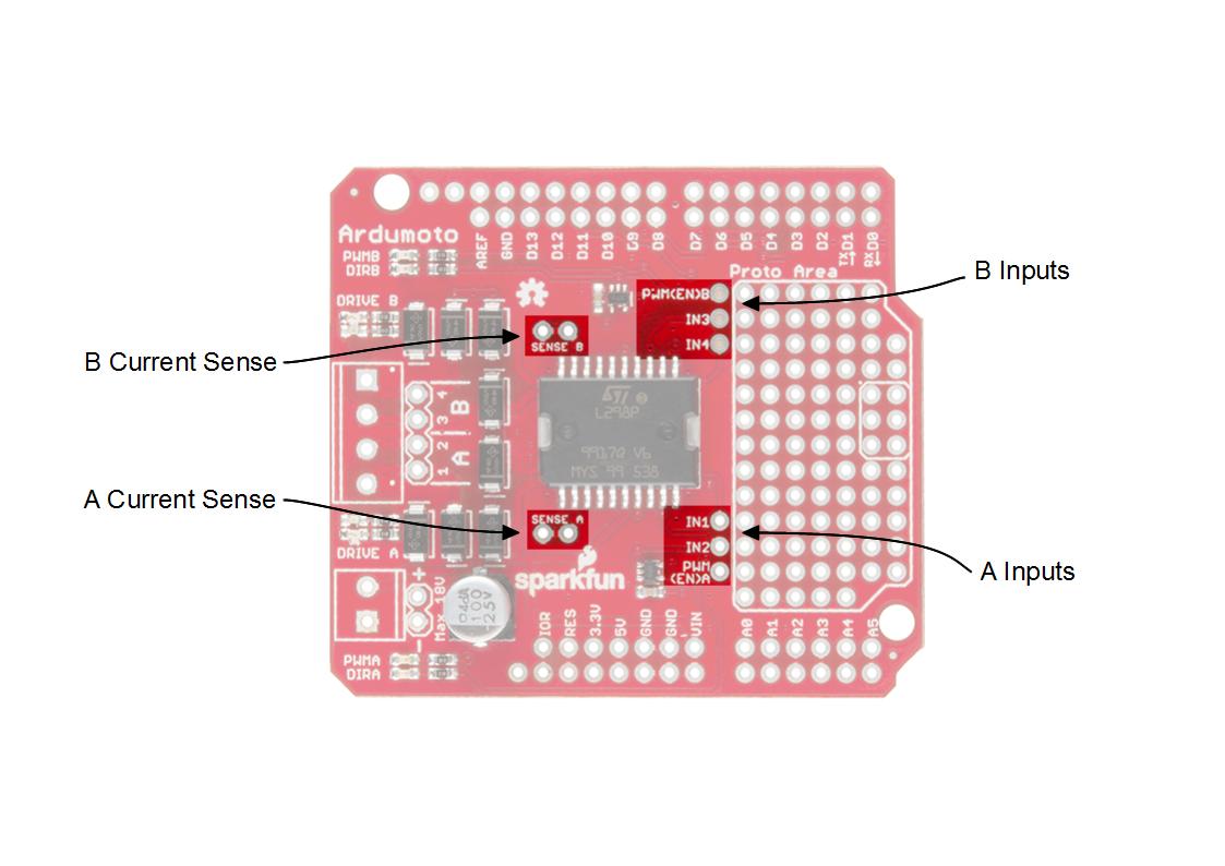
Pins and Connectors
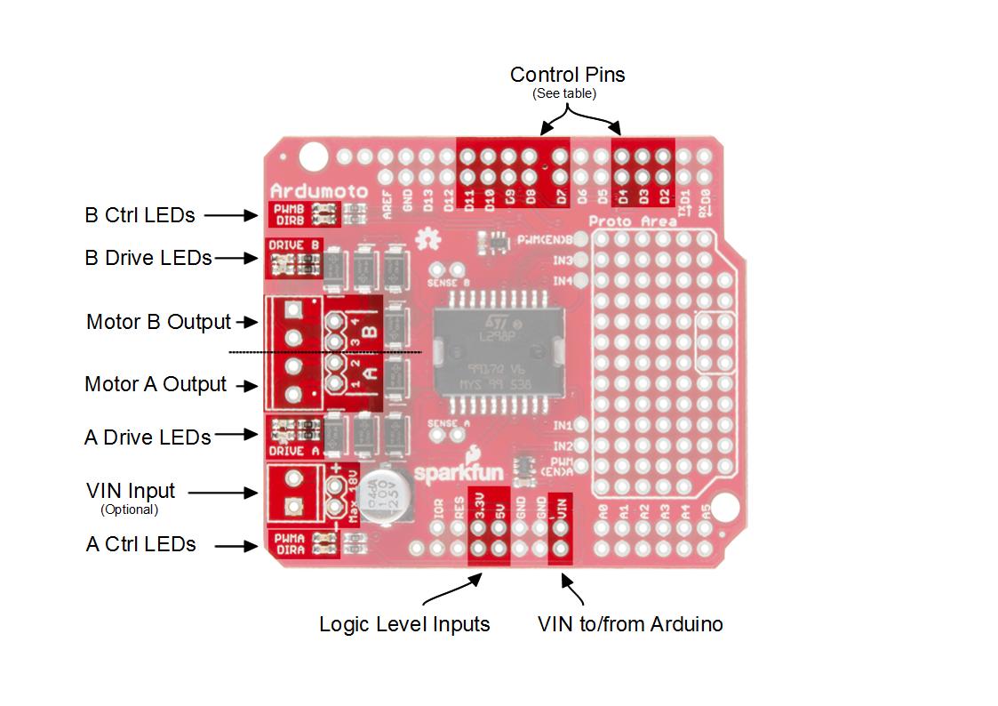
Here's an annotated view of the shield, highlighting the important pins and components:
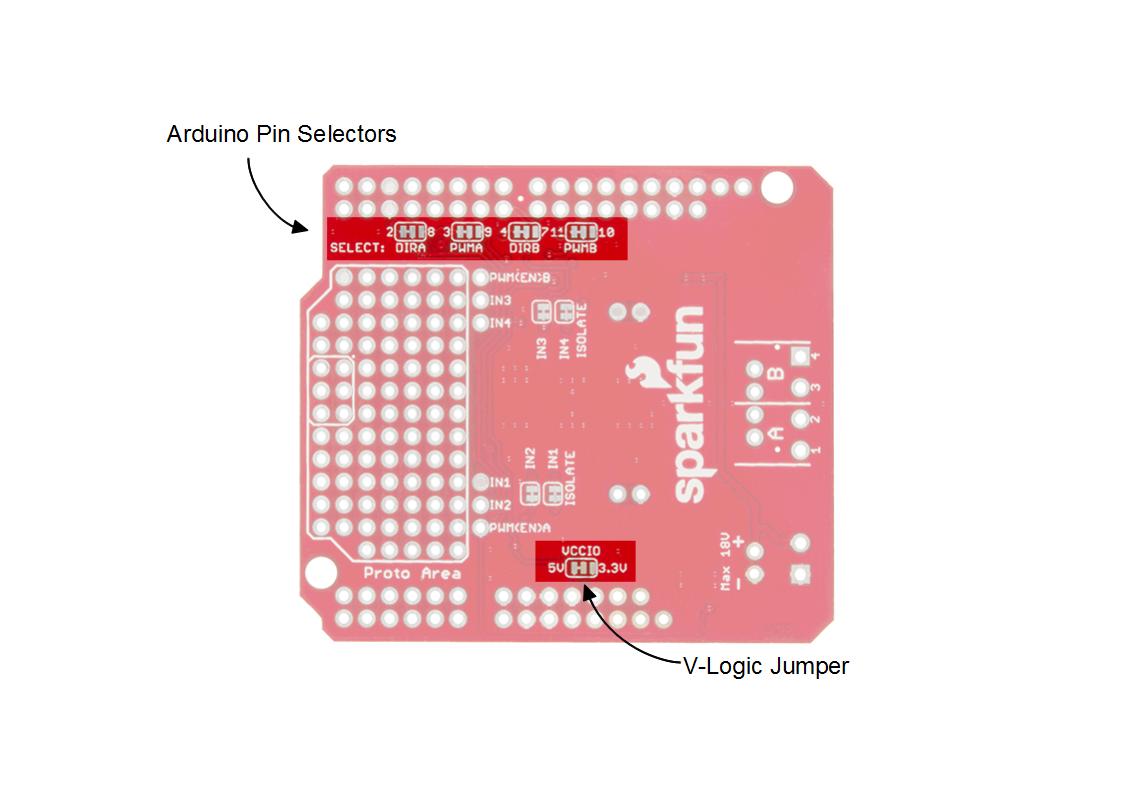
Each motor uses two pins: the digital output for direction and the PWM for speed. The factory configuration uses Arduino pins 2, 3, 4 and 11. The alternate configuration uses pins 7, 8, 9 and 10. If the alternate pins are needed, you'll have to cut the copper links on the bottom and apply solder to bridge to the other selection where necessary. For this guide, just leave everything in the default positions.
If the shield is used on a 3.3V Arduino (such as the Arduino Pro 328 - 3.3V/8MHz), chances are there's no 5V supply, so you'll have to move the VCCIO jumper to the 3.3V side. This jumper selects the voltage for the L298's logic. If you're using an Uno, or 5V 328p of another variety, leave this in the default position.
This table describes the pin function for each configuration.
| Default Pin |
Alternate Pin |
Ardumoto Shield Pin Label | Notes |
|---|---|---|---|
| 2 | 8 | DIR A | A digital signal to control the rotation direction of motor A (e.g., HIGH drives current from output 4 to 3). |
| 3 | 9 | PWM A |
A PWM signal to control the speed of motor B. 0=off, 255=max speed. |
| 4 | 7 | DIR B |
A digital signal to control the rotation direction of motor A (e.g., HIGH drives current from output 2 to 1). |
| 11 | 10 | PWM B |
A PWM signal to control the speed of motor B. 0=off, 255=max speed. |
While the Ardumoto Shield is attached to an Arduino, the used pins shouldn't be connected to anything else.
Motor Outputs
Both of the L298's motor driver outputs are broken out to the edge of the shield. These 2-pin outputs are broken out to two footprints: a 3.5mm-pitch screw terminal and a 0.1"-pitch header. You can use either to wire up your motor, but screw terminals make life much easier if you need to disconnect your motor. The L298 is perfect for building simple two-wheel-drive robot platforms --- connect one motor to port A and the other motor to port B.
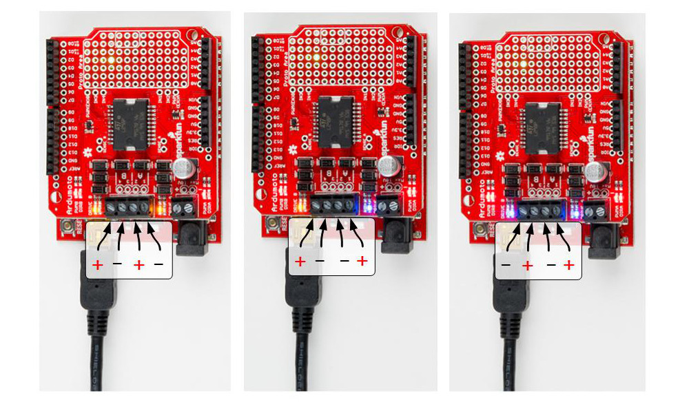
Technically, there is no right or wrong way to connect your motor's wires to the two output pins, but to help keep things straight, we suggest connecting the red / black wire for each motor to pins 1 / 2 on port A and pins 3 / 4 on port B, respectively.
The right and left motors of a robot spin different directions with the same polarity drive because of the orientation. If you want to keep DIR consistently moving that side of the bot "forward," you may end up swapping either the motor leads of one side or the logic in the code, but not both. Play around with the leads of the motors on their respective sides and watch the indicator LEDs to see the effect.
LED Indicators
Next to each of the motor outputs is a pair of blue and yellow LEDs, which indicate the direction your motor is spinning. These are great once you get to debugging your project. They're also useful if you want to test your sketch without wiring up any motors.
There are also four red LEDs (PWMA, DIRA, PWMB, DIRB) that are wired to the control lines directly, showing what your code is doing and also if the pins are configured correctly.
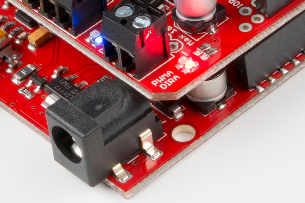
When the DIR LED of a side is illuminated, the driver will allow current from pin 2 to 1, and the blue LED will be lit. Alternately, the yellow LEDs will be lit. With a motor connected, the inductive effects can cause the opposite drive LED to illuminate slightly; this is OK. The blue and yellow LEDs are there to help show what the actual outputs of the driver are doing. Use the red LEDs to debug your code.
Supply Voltage
The Ardumoto Shield should be powered through one of two power supply inputs. Pick one or the other:
- The barrel jack input on the Arduino.
- The VIN input on the shield
If you don't want to use the Arduino's barrel jack input, you can use the VIN input on the shield instead. This voltage input will supply both the shield and the Arduino. Like the motor outputs, this connection is broken out to both a 3.5mm screw terminal and a 0.1"-pitch header.
Do not supply power to both the Arduino barrel jack input and VIN on the shield! Doing this will cause current to flow from one power supply to the other if the voltages are not identical.
Spec'ing a Power Supply
Because VIN powers both your Arduino and your motors, you need to take extra care in deciding what you'll use to power your Arduino/Ardumoto combo. Not only does VIN have to fall within the acceptable range of your Arduino (usually 6--15V), but it also has to meet the specifications of your motor.
Check the voltage and current requirements of your motor before deciding how to power your Ardumoto project. These specifications vary. The 65 RPM Hobby Gearmotors, for example, have a recommended range of 3--6V, but can be safely powered at up to 9V.
We recommend 9V alkaline batteries as an easy, if not very sustainable, option. Dual-cell LiPo battery packs (7.4V nominal, 1,000mAh capacity) are also a good option if you're looking for something mobile. A 9V wall wart can work if your project is stationary. For more help picking a power supply, check out our How to Power a Project tutorial.
Ardumoto Shield Assembly Tips
Before you can start using the Ardumoto Shield, you have to do a little assembly. Embrace your inner electronics technician and whip out that soldering iron! Time to turn a mish-mash of parts into a fully functional 'duino shield!
On this page we'll go over some assembly tips. You don't have to follow these steps exactly (assemble the shield as best fits your project's needs), but this is good for general use of the shield.
Add Screw Terminals (Optional)
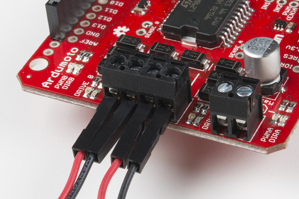
If you please, you can add screw terminals to both of the motor outputs and/or the VIN input.
If you're adding screw terminals to the motor outputs, slide them together first:
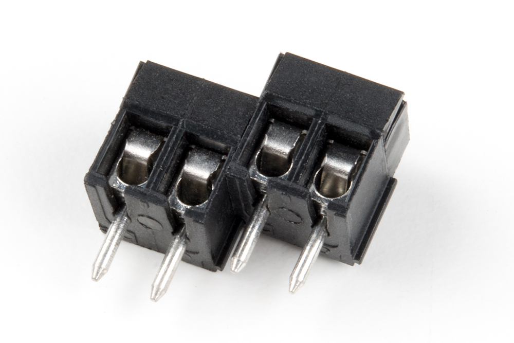
Then insert them into the shield and solder.
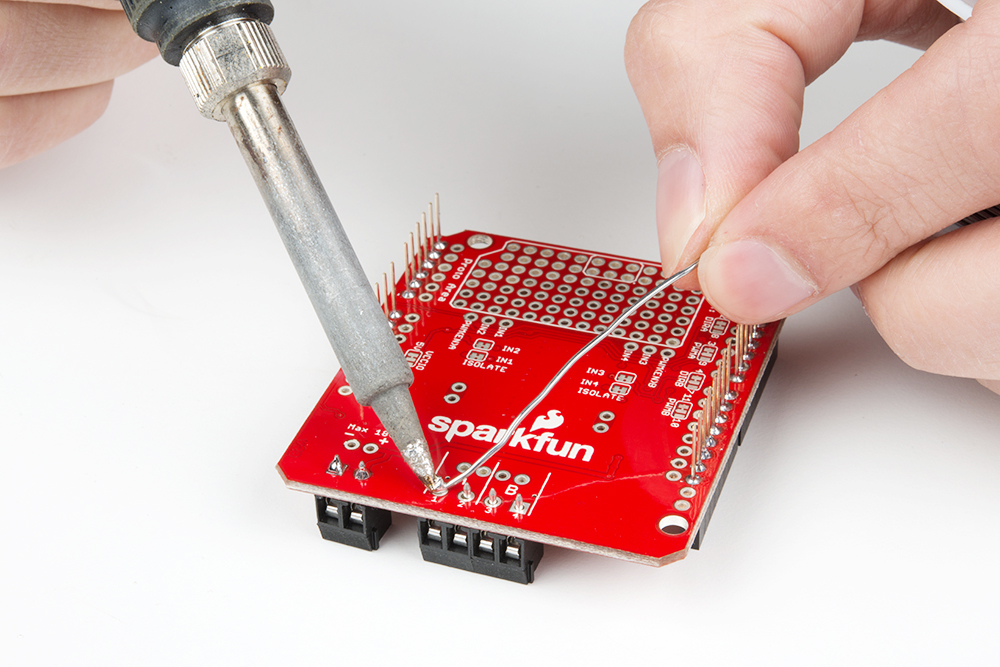
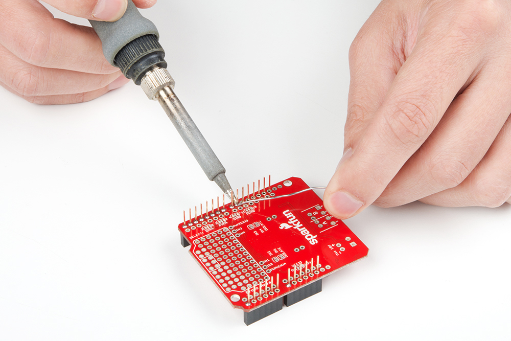
Solder the Arduino Headers
To interface the shield with your Arduino, soldering male connectors to the 28 header pins is a must. Soldering ensures a reliable physical and electrical connection. If you've never soldered before, check out our through-hole soldering tutorial.
There are usually two options for connectors when you're assembling a shield: stackable or straight. We recommend stackable headers because they allow you to stack other shields or jumper wires on top. The smaller male headers are a good option if you're looking for lower-profile installation.
If this is your first shield assembly, we recommend reading through our shield assembly guide. There are all sorts of tricks to installing shield headers, and making them look as good and straight as possible!
Once you're done soldering the headers, plug the shield in to make sure everything fits nice and cozy.
Prototyping Area
Let's address the elephant in the room. There's almost half a shield that we've failed to talk about thus far: the prototyping area! These rows and columns of 0.1"-spaced plated through-holes can be used to solder in all sorts of fun components.
Near the proto area is a set of six pins. With the isolation jumpers opened underneath, these allow you to interface directly to the inputs of the L298.
The six pins of the ISP connector are outlined within the proto area. These are just plated through holes, and are labeled to warn you that the pins underneath come up really close. If you absolutely need these, you may end up removing the ISP header from the attached Arduino.
Here are some ideas of what to do with it:
- Leave it alone! --- If you're happy with just driving motors, you're good to go.
- Add an accelerometer to enable bump detection in your robot.
- Fill it with LEDs to make your project as blinky as possible.
- Add current sense resistors, an op-amp, and measure the current of the motors being driven.
- Disconnect all the jumpers and wire up the L298 in any way you please.
Unlike other prototyping areas you may have encountered in the past, these holes are not wired together. You don't need to do any trace-slicing, but you will need to do some soldering and wire routing.
Motor and Wheel Assembly
This is where the shield assembly gets very project-specific. Have you picked out which motors you'll be driving with the shield? Do you know how long the wires need to be trimmed? There's a lot to be answered here before continuing on...
Motor Wiring
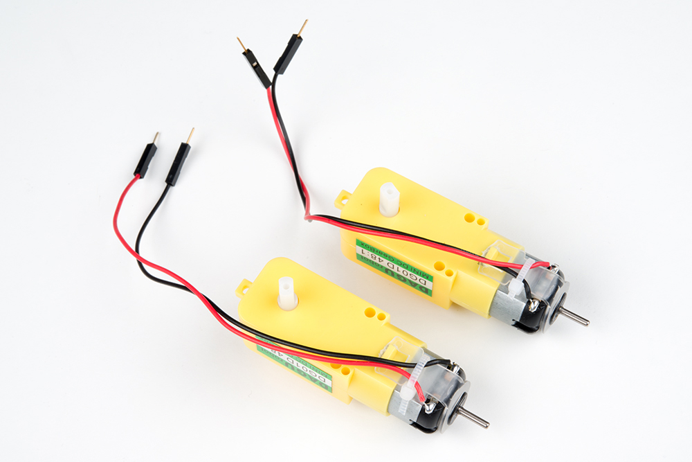
If you have the kit, the motors come with wires attached, but take the time to notice how they are wired. They are a left-right pair, which can be seen by holding the motors in the same orientation and looking at how the red and black wires are attached. When they are installed with the wire-side facing each other, a positive polarity drives either motor "forward," even though one is spinning clockwise while the other spins counterclockwise.
Connecting Motors
If you added screw terminals in the last step, break out your screwdriver, slide the wires in, and tighten the terminals down.
In lieu of screw terminals, you can solder the motor wires into either the 0.1" header or the screw terminal header.
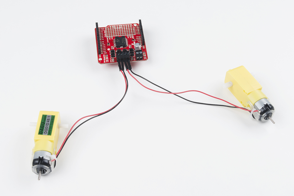
If you've got the kit, install one motor's red to output '1', and black to output '2'. Install the other motor's red to output '3', and black to output '4'.
Upcycling the SparkFun Box
If you have the Ardumoto Shield Kit, you probably also have a robust, resplendently red SparkFun box. These SparkFun boxes come in handy for all sorts of projects --- including robot chassis!
With some measured hobby knife incisions, you can cut out some mounts for the motors and tie your Arduino/shield combo down as well:
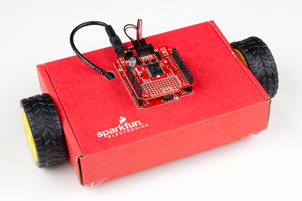
This shape of robot relies mostly on balance, and slides across the floor. If driving on carpet, slick clear tape can be added to the corners to prevent catching.
Example Code
Controlling the Ardumoto Shield is super easy. If you can blink LEDs, you can make the Ardumoto Shield spin its motors. Here, we'll provide a simple, expandable example sketch to show how to drive the pair of motors on the Ardumoto.
Note: This example assumes you are using the latest version of the Arduino IDE on your desktop. If this is your first time using Arduino, please read our tutorial on installing Arduino IDE. If you have not previously installed an Arduino library, please check out our installation guide.
The Example Sketch
Download the example sketch and upload it to your board.
language:c
    /* Ardumoto Example Sketch
  by: Jim Lindblom
  date: November 8, 2013
  license: Public domain. Please use, reuse, and modify this
  sketch!

  Adapted to v20 hardware by: Marshall Taylor
  date: March 31, 2017

  Three useful functions are defined:
    setupArdumoto() -- Setup the Ardumoto Shield pins
    driveArdumoto([motor], [direction], [speed]) -- Drive [motor]
      (0 for A, 1 for B) in [direction] (0 or 1) at a [speed]
      between 0 and 255. It will spin until told to stop.
    stopArdumoto([motor]) -- Stop driving [motor] (0 or 1).

  setupArdumoto() is called in the setup().
  The loop() demonstrates use of the motor driving functions.
*/

// Clockwise and counter-clockwise definitions.
// Depending on how you wired your motors, you may need to swap.
#define FORWARD  0
#define REVERSE 1

// Motor definitions to make life easier:
#define MOTOR_A 0
#define MOTOR_B 1

// Pin Assignments //
//Default pins:
#define DIRA 2 // Direction control for motor A
#define PWMA 3  // PWM control (speed) for motor A
#define DIRB 4 // Direction control for motor B
#define PWMB 11 // PWM control (speed) for motor B

////Alternate pins:
//#define DIRA 8 // Direction control for motor A
//#define PWMA 9 // PWM control (speed) for motor A
//#define DIRB 7 // Direction control for motor B
//#define PWMB 10 // PWM control (speed) for motor B


void setup()
{
  setupArdumoto(); // Set all pins as outputs
}

void loop()
{
  // Drive motor A (and only motor A) at various speeds, then stop.
  driveArdumoto(MOTOR_A, REVERSE, 255); // Set motor A to REVERSE at max
  delay(1000);  // Motor A will spin as set for 1 second
  driveArdumoto(MOTOR_A, FORWARD, 127);  // Set motor A to FORWARD at half
  delay(1000);  // Motor A will keep trucking for 1 second
  stopArdumoto(MOTOR_A);  // STOP motor A

  // Drive motor B (and only motor B) at various speeds, then stop.
  driveArdumoto(MOTOR_B, REVERSE, 255); // Set motor B to REVERSE at max
  delay(1000);  // Motor B will spin as set for 1 second
  driveArdumoto(MOTOR_B, FORWARD, 127);  // Set motor B to FORWARD at half
  delay(1000);  // Motor B will keep trucking for 1 second
  stopArdumoto(MOTOR_B);  // STOP motor B

  // Drive both
  driveArdumoto(MOTOR_A, FORWARD, 255);  // Motor A at max speed.
  driveArdumoto(MOTOR_B, FORWARD, 255);  // Motor B at max speed.
  delay(1000);  // Drive forward for a second
  // Now go backwards at half that speed:
  driveArdumoto(MOTOR_A, REVERSE, 127);  // Motor A at max speed.
  driveArdumoto(MOTOR_B, REVERSE, 127);  // Motor B at max speed.
  delay(1000);  // Drive forward for a second

  // Now spin in place!
  driveArdumoto(MOTOR_A, FORWARD, 255);  // Motor A at max speed.
  driveArdumoto(MOTOR_B, REVERSE, 255);  // Motor B at max speed.
  delay(2000);  // Drive forward for a second
  stopArdumoto(MOTOR_A);  // STOP motor A
  stopArdumoto(MOTOR_B);  // STOP motor B

}

// driveArdumoto drives 'motor' in 'dir' direction at 'spd' speed
void driveArdumoto(byte motor, byte dir, byte spd)
{
  if (motor == MOTOR_A)
  {
    digitalWrite(DIRA, dir);
    analogWrite(PWMA, spd);
  }
  else if (motor == MOTOR_B)
  {
    digitalWrite(DIRB, dir);
    analogWrite(PWMB, spd);
  }
}

// stopArdumoto makes a motor stop
void stopArdumoto(byte motor)
{
  driveArdumoto(motor, 0, 0);
}

// setupArdumoto initialize all pins
void setupArdumoto()
{
  // All pins should be setup as outputs:
  pinMode(PWMA, OUTPUT);
  pinMode(PWMB, OUTPUT);
  pinMode(DIRA, OUTPUT);
  pinMode(DIRB, OUTPUT);

  // Initialize all pins as low:
  digitalWrite(PWMA, LOW);
  digitalWrite(PWMB, LOW);
  digitalWrite(DIRA, LOW);
  digitalWrite(DIRB, LOW);
}
Then upload to your Arduino and watch your motors spin! If you want to dig really deep into the sketch, check out the comments.
Explaining the Sketch
For each motor there are two mechanisms we can control --- the direction of rotation and the speed. Each of those mechanisms is controlled by one pin on the Arduino.
Controlling Rotation Direction
We can only spin the motor in two directions --- clockwise or counterclockwise --- so we only need two values --- 0 or 1 --- to control that from the Arduino. We can simply digitalWrite either of the direction pins (pin 12 for motor A, pin 13 for motor B) HIGH or LOW to go forward or backward.
For example, if you want motor A to spin clockwise, you simply need to digitalWrite pin 12 LOW:
language:c
digitalWrite(12, LOW);  // Motor A will spin clockwise
To make it spin the other way, write the pin HIGH.
language:c
digitalWrite(12, HIGH);  // Motor A will spin counter-clockwise
(Note: The rotation direction depends on how you wired the motor to your shield. If you swapped the red and black wires, the motor will spin opposite of how we've described it here.)
Speeding
To control the speed of a motor we need to analogWrite to the PWM pins (pin 3 for motor A, pin 11 for motor B). A higher analogWrite value means a faster spin. Writing the pin LOW (or 0) will stop the motor.
| PWM Value | Motor Spin Speed |
|---|---|
| 0 | Off (Stop) |
| 127 | Half Speed |
| 255 | Full Speed |
If we want to turn motor A up to maximum speed, this is all we need:
language:c
analogWrite(3, 255);  // Motor A at max speed
After that line of code is executed, the motor will spin until stopped. To stop the motor, replace 255 with 0:
language:c
analogWrite(3, 0);  // Stop motor A
Don't forget to set your direction before spinning your motor!
Resources and Going Further
The Ardumoto has been designed primarily to be a motor driver, but we've taken extra time to make sure the L298 IC can be fully controlled, given the user understands the way it works. The datasheet contains a schematic diagram of the internal functions of the IC, which is the first thing to look at and contemplate before trying to do wacky things with your Ardumoto.
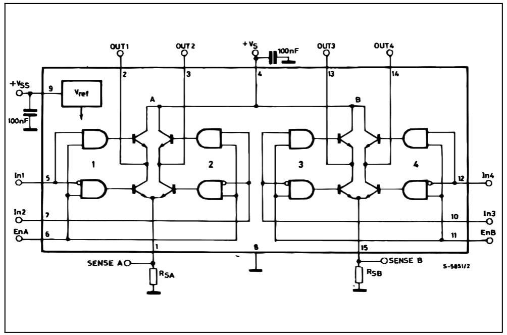
As can be seen from the block diagram, the L298 is actually four totem drives with two common grounds, intended for full-bridge motor-driving applications.

To make the Ardumoto, we've connected the pairs with one of each inverted, to allow a direction control. The enable pin is then PWM'd such that the output goes between drive enabled and high impedance. This allows coasting of the motors when not driven.
Another way the motors could have been hooked up is to PWM the input pins and keep enable high. This would provide motor resistance against movement when not under power, and a PWM value of 1/2 would be "off."
Advanced Pins and Connections
The other jumpers and pins are for flexible configuration. They allow the L298 to be completely isolated from the control lines so that it may be connected in very specific ways, but it's up to you to figure out how to solve the engineering problems you'll face.
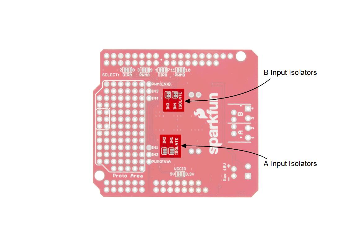
The A/B Isolate jumpers and the A/B inputs work together. If the 'ISOLATE' jumpers are all opened, and the 'SELECT' pins are all opened, the inputs to the L298 are not connected to anything but the six input pins by the proto area. They can then be used however the designer wishes in conjuction with the proto area.
The other curious feature is the pairs of pins labeled 'SENSE'. If you look closely, you'll notice each pair is shorted together, and connected to ground. It is possible to detect current through each motor by cutting the jumper between these pins, supplying a low-ohm resistor and measuring the voltage across it. Not for the faint of heart.
Possible uses:
- Current sense --- break the current sense link between through-holes and insert a 0.05 or 0.1 ohm resistor. Then, use an op-amp to amplify the voltage across the resistor to measure current with an ADC.
- Four independent totem drive circuits using both timer one and timer two.
- Non-coasting drive configuration.
- Bridging output (and control lines) for 4A single drive --- add a heatsink with thermal tape!
Resources
- Ardumoto Shield Schematic --- A PDF of the shield's schematic.
- Ardumoto Shield Github Repository --- The design files and examples.
- L298 Data Sheet --- Everything you could ever want to know about the L298 dual-motor driver.
- Secrets of Arduino PWM -- Gives a good description of low-level timer usage.
- Example Using TimerOne --- This example included with the product repo shows using the motor driver with the TimerOne library.
Going Further
- HUB-ee Buggy Project --- Build your own buggy using an Ardumoto shield.
- Assembly Guide for RedBot --- If you're looking for a complete, beginner-level robotics platform, check out the RedBot Kit. It's Arduino-compatible, and the RedBot Mainboard has a motor driver built into it, so you don't even need an Ardumoto Shield.
- Getting Started with the MiniMoto --- The MiniMoto is a more advanced, digitally controlled, low-voltage DC motor driver. Great if you need a smaller form-factor motor controller.
- How to Power a Project --- Batteries? Wall warts? Solar? If you're not sure how to power your Ardumoto Shield project, take a trip over to this tutorial.